|
|
|
|
|
I was lucky enough to have been passes on a compressor flow map for the Eaton M112 supercharger which has allowed me to do some futher calculation related to its drive's gearing ratio and therefore the diameter of crankshaft pulley that I'll need for it. Firstly, the 2922cc engine capacity converts out to 178 cubic inches. I used 6500rpm as maximum operating speed (I believe that the stock rev limiter operates just a little below this point), and estimated its volumetric efficiency at 85%. This produced a calculated peak naturally aspirated airflow rate of 285 CFM. I then multiplied this out by the pressure ratios for a couple of likely boost pressures of 7 and 10psi, plus one at a possible future pressure of 12psi as follows:- 7psi......1.47 PR x 285 CFM...... 419.0 CFM 10psi.....1.68 PR x 285 CFM...... 478.8 CFM 12psi..... 1.8 PR x 285 CFM...... 517.6 CFM I'm not sure of either the altitude at which I live or that at which the car will generally be used, but it shouldn't be all that much above sea level in any case. I have therefore ignored any altitude correction factor as I reckon it would be close to unity for me anyway. After loosely converting cubic metres per hour into CFM, (and marking them onto the compressor flow map) I plotted these points of CFM and PR as well as the atmo flow rate at a PR of 1. I also highlighted the likely range of supercharger driven speeds as shown on the map and roughly interpolated between them to make reading off the slope a little easier. This produced a straight line on the map as shown below ....  This is very interesting, as my previous calculations only from basic flow charts for the M112 had shown that at an engine speed of just under 6500rpm I should be looking to drive the supercharger at around 9500 for what I wanted... or approximately an overdrive of 50%. According to the compressor map though from my calculations driving the supercharger at 9500 rpm like this would produce a pressure ratio of about 1.94 and an airflow rate of something like 550 CFM at a thermodynamic efficiency of about 56%, which would produce a theoretical power figure of something like 374bhp. To do that would require a further drop in compression ratio beyond the smaller CR reduction that I would plan to do a little later on and the zero reduction when this 'temporary' installation is fitted initially to the stock N/A engine. In fact, the compressor map would suggest that for a pressure ratio of between 1.5 and 1.7 I should only be looking to drive the supercharger at between roughly 7500 and 8500rpm.... a good bit slower than I had calculated earlier. This could mean that the crankshaft pulley could end up being smaller than is able to be physically bolted onto the existing crankshaft vibration damper fixings, and I may even be forced to fit a larger supercharger pulley to compensate and bring its driven speed down! As a starting point, I think I will start with the smallest diameter crankshaft pulley that I can make work and be prepared to either go bigger with it or bigger on the supercharger pulley depending on what real life testing on completion shows up. It is safer to start off with a small crankshaft pulley and then increase its size later as neccessary. Time for some drive gearing ratio calculations I think..... |
| |
|
|
|
|
|
|
|
|
|
I thought I'd post this sheet up as it could be useful to others doing something similar. It is interesting when read in conjunction with the compressor flow map shown above.  The first three columns will apply to any B6304 engine whether it is being turbocharged or supercharged. The fourth column gives the supercharger speed at which these boost pressures and airflow rates will be obtained. The fifth column gives the supercharger drive ratio, and the sixth lists the crankshaft pulley diameter that is required to give that drive ratio with the standard 75mm supercharger driven pulley. Up to about 9psi of boost compressor efficiency is pretty steady at 60%, but by 10psi it has dropped into the 58% island and at 15psi it is down somewhere between 54% and 56%. Above a rotational speed of 10,000 rpm efficiency is falling away rapidly at all airflow rates and pressure ratios. From the compressor flow map shown earlier the M112 would appear to be quite a good choice for use with a B6304, given that it is quite an old unit now and not as efficient overall as a later 4-lobe TVS type. In short then, if you want to have more than about 1 Bar of boost pressure (or more accurately a pressure ratio across the supercharger of more than about 2.0 in any arrangement), forget about using a supercharger and get a nice big turbo instead.....or possibly consider using both! |
| |
Last Edit: Jan 4, 2014 23:00:50 GMT by turbeam: Forgot to add data sheet!
|
|
|
|
|
|
|
|
A word of warning .... don't believe everything that you are told, even by the experts!
Earlier on in this project I had contacted a company who make large diameter crankshaft pulleys for use in the XKR8 and other similar cars using this dsame supercharger. I was keen to find out the outer diameter of the stock Jaguar crankshaft pulley, and on asking was told that it was 170mm. This was before I had found the compressor flow map for the unit that is shown above.
As I started to look more closely into reaching a starting point diameter for making my own one-off pulley though, this just didn't make any sense at all. I double and triple checked my calculations, but for a time began to think that I must have been getting some part of a formula wrong or not making allowance for an important factor or something.
Only after searching the web for any further details on the Jaguar did I find two articles that mentioned the stock compressor drive ratio. One stated this as being 1.9:1 and another as 1.87:1.
Without going deeply into any calculations for the Jaguar engine, these ratios at a crankshaft speed of 6000rpm would give a supercharger driven speed of between 11,220 and 11,400 rpm.... right on the money for the top end of the Jaguar engines speed range and just at the point where the supercharger efficiency is starting to drop off rapidly.
The problem though is that when used with the standard 75mm supercharger driven pulley, that ratio would equate to a crankshaft pulley of about 140mm diameter.... nowhere near the 170mm diameter that I had been 'reliably informed'. A 170mm crankshaft pulley by my calculation would give a drive ratio of 2.29:1 and at 6000rpm engine speed would be turning the supercharger at 13,700 rpm. That is really well out of its comfort zone and would only be at about 40% efficiency.
I can see only four possibilities as to why I was told the stock pulley was of 170mm diameter.
1) The person I spoke to had a slight 'senior moment' and either got a bit mixed up between the diameters of the stock pulley size and their own overdrive version or simply gave me a totally wrong size by mistake.
2) The same person thought I was enquiring about the diameter of their own overdrive pulley.
In these first two cases, now with the compressor flow map to compare against, it doesn't look very kindly on their product if it really is that size. It will just be trying to push a greater volume of much hotter and less dense air through the same parts such as the already questionably proportioned stock chargecoolers. At this drive ratio, efficiency is unlikely to go over 50% at best even at much lower engine speeds.
Overdriving the supercharger like this sounds OK in theory, but in this case it works out really badly.
3) The person I spoke to was just cleaning up in the workshop at the time I contacted them, generally isn't allowed to touch anything sharp and has more enthusiasm than knowledge, and just plucked a dimension out of the air.
4) Whoever it was, they were deliberately giving out false information and trying to decieve or throw me off on a false path to prevent me getting enough info from which to copy their part.
I don't know which of these I like least, but I'd prefer to think it was just a simple error as in 1)... we all make the odd mistake.
Even after doing the calculations there is still an element of 'suck it and see' in the real world, so I'm going to start off with a crankshaft pulley of 114mm diameter as this is the smallest size that will easily fit on the end of the crankshaft, but it still gives a pressure ratio that is a little higher than I was initially planning to have.
It just goes to show though, don't take everything you hear or read, even from 'experts' as gospel.....
|
| |
|
|
|
|
|
|
|
|
glad i found your thread jim, fabrication work on the shell and the V8 crossmember and the build vid/pics on EGA is impressive!
I'm no blower expert... i fitted an eaton M45 to an old 8-valve scirocco some years back and found that gearing it over 1:2 (12000rpm max blower) would just heat the charge too much and give no increase in power, with around 1:1.8 being optimum. But with the same setup on the 16-valve golf KR engine it gave far more power and the blower ran cooler (but with less psi on the gauge despite both being the same bore/stroke/capacity) due to the larger valve area in the KR being able to flow all that extra air at higher rpm rather than bottling it up.
The difference between a static calculation and what psi you end up with on the gauge seems to have a lot to do with the tune of the engine and the flow through the whole system which is difficult to anticipate on the side of the engine because it hinges on an interaction between 2 systems that both have varying dynamic flow rates (this isn't helping i know...) but you could start with 1:1.3 pulley ratio and see where that gets you?
I have an M112 i was going to fit to the M60 V8 at some future point so i will be watching your project keenly. I couldn't find a source on the web for the original XKR pulley overdrive either... perhaps it's a big secret
|
| |
|
|
|
|
|
|
|
|
Thanks Sam, I'm glad you like them.
I totally agree with your thoughts on the supercharger driven speeds. Despite what Mercedes like to badge their cars equipped with the Eaton 'chargers as, these aren't really compressors at all but simply displacemnent air pumps. The pressure they generate comes about purely because the engine downstream of them creates a flow restriction to their outputr airflow rate, and an engine that presents less of a restriction in this way, such as a multi-valve engine will flow more air and also give a lower boost pressure....often with less heat being produced by the supercharger (greater efficiency part of the map) and lower intake temperatures. Win-Win.
I think that it would be almost impossible to get the drive ratio spot on at the first attempt, but we have to start somewhere and the compressor flow map and some basic calculations are probably the best place to set out from. My original thoughts were to start off with about half a bar of boost (7psi or 8psi) which according to the chart above would require a supercharger driven speed of about 7500rpm and therefore a crankshaft pulley of about 85mm in diameter.
Due to the design of the crankshaft vibration damper mounting on this engine, an 85mm pulley would clash with its hub fixings and would have to be made in two parts bolted together to allow for this. The smallest one-piece pulley that would fit, at 114mm, would give more than twice that level of airflow rate, the actual boost pressure produced is only calculated, but at 15psi is a good bit too high for the stock engine's compression ratio.
As I type this, it occurs to me that making a two part mounting and pulley is really the best option, and I could have a pair of pulleys of 85mm and 95mm made to give calculated boost pressures of about 7-10psi.
On the subject of compression ratios for supercharging, there is another option on twincam engines that is yet to be explored.
As my current CR is a bit on the high side for use with supercharging, I'm thinking of experimenting with retarding the inlet cam timing a bit (closing it later).....in a similar way to on a Miller Cycle engine, rebalancing the compression and expansion ratios? That is something to play with a bit later on.
|
| |
|
|
benzine
Part of things

Posts: 333
Club RR Member Number: 87
|
|
Jan 10, 2014 10:12:28 GMT
|
|
Great thread & car! Looking forward to hearing straight six + S/C. I used to have a B6304 in my kit car, it sounded superb
|
| |
|
|
|
|
|
Jan 10, 2014 12:22:43 GMT
|
Cheers Benzine, the sound of these engines is typical straight six but they do have a quite destinctive 'metallic' tone to their exhaust note I'm told, like "a roaring mechanical tiger". People regularly comment on how nice the B6304 engine sounds when used in anger without catalytic convertors fitted and less restrictive silencing. I don't usually get to hear it directly myself and it sounds a bit different from inside the car (such as in the earlier video clip) but I do have some external footage somewhere of the car climbing a steep twisty hill in the borders where the noise is echoing and bouncing around right through the whole valley, and it does sound wonderful. Funnily enough though it is very quiet when driven more gently. This car is using a pair of standard Audi 80 stainless steel rear silencer boxes and I'm very happy with their combination of characteristics. Not a great photo of the exhaust system, just taken when on the trailer showing an experimental rear anti roll bar that proved to be much too low!... 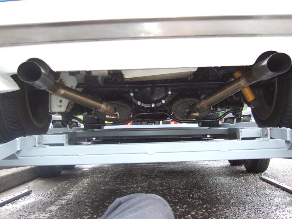 What were you using for silencing on your kit car? The 5-cylinder version of these engines also sound very good when on song, but different again, somehow the six just sounds both more smooth and rev-happy? If/ when the twin turbo engine is eventually installed I think much of that lovely sound will be absorbed and softened by the turbine wheels, which is something that would be nice about using the supercharger instead. The current exhaust manifolds were only ever intended for short term N/A use though...  ... and if I end up preferring the supercharger installation I'll have to make some better exhaust manifolds to match.... I think some of the 6-cylinder BMW manifolds in stainless steel like this would be a good starting point for modifying to use on this engine..... www.ebay.co.uk/itm/BMW-E46-E39-Z3-Stainless-Steel-Race-Exhaust-Manifolds/380813956700?_trksid=p2047675.m1850&_trkparms=aid%3D222002%26algo%3DSIC.FIT%26ao%3D1%26asc%3D19803%26meid%3D4017645535322568457%26pid%3D100011%26prg%3D8916%26rk%3D2%26rkt%3D5%26sd%3D380784674415%26 |
| |
|
|
benzine
Part of things
Posts: 333
Club RR Member Number: 87
|
|
Jan 10, 2014 12:35:05 GMT
|
What were you using for silencing on your kit car? I was using a single cheap kit car silencer, wasn't very good quality and didn't do a great deal of silencing  |
| |
|
|
lowen
Part of things
Posts: 47 
|
|
Jan 10, 2014 19:52:59 GMT
|
|
It's quite suprising how much air can flow through small pipes, I have a 22mm inside diameter bypass pipe with several bends, fed by a recirculating valve and is able to drop the boost on my 2.5 diesel from 24psi to 18psi
I found a series heater matrix seems to transfer heat quite well, it has a large amount of fin surface area and tubes running through it plus air travels over the fins quite well. I'm currently in the process of getting it plumbed in and temperature guages to wire to test it out.
On the dynamic boost subject, my Land Rover is geared for around 8.75psi theoretically, but at idle it only has 3psi at idle, this quickly rises - about 2000rpm its around 8psi. A few years back I tried making up an excel spreadsheet to work out power output of the a-series mini engine from capacity, boost, heat, efficiency, etc and was fairly accurate / believable, but I found you can spend more time trying to work it out with so many variables than trying a few pulleys. In the end I decided on common sense to be a starting point.
|
| |
|
|
|
|
|
Jan 10, 2014 21:01:28 GMT
|
My thoughts on heat flow into a heater matrix rather than out of it as designed was that rather than the airflow passing through the whole length of the element and have lots of short fins to transfer heat out of it, it only makes a short journey over the width of the fins to transfer its heat and these must be sufficiently cooled by the water passages. I simply wasn't sure how well this would or wouldn't work in my arrangement, but it could have resulted in a lot of time consuming fabrication work that might have ended up being scrap. Given that time is tight, my gut instinct was to stick with a tried and tested air-air intercooler set up. The second factor is that a charge cooler would have restricted space around the right hand side of the engine even more. I agree, it is a good idea to run through as many theoretical calculations with regards to correct drive ratios etc before laying hand on spanner, but when it comes down to it only actual real world testing of the complete installation will be able to pin down the best final spec of the particular application. As it will be fairly easy to have alternative crankshaft pulleys made, I'm planning to err on the small side initially and increase the airflow and boost pressure progressively with alternative pulleys as I gain more data on what this produces at each step on one of these engines. I was looking through some old photos tonight and found this one which is quite interesting. In the centre is a standard Sunbeam Lotus ZF gearbox, except here fitted with a PRV V6 bellhousing as at one point was going to be used in turbocharged form in the car. If anyone is looking for a PRV V6 I still have a few left over from this project. On the right is the Borg Warner T5 gearbox as fitted in the Sierra Cosworth, but this one is mated to a Volvo Whiteblock bellhousing and is awaiting fitment in EGA along with the new twin turbo engine. On the left is the 6-speed Getrag from the BMW M5 that is also waiting to be installed in the new M62 V8 powerted Sunbeam. The BW-T5 needs its operating rods and casting shortened to put the gear lever in the correct position for use in EGA. The 6-speed Getrag has external linkages that are much more easily shortened for use in the V8 car. The dimensional differences around the bellhousing and gearbox casing areas are quite obvious here....  Many people have heard that the stock BMW M60 and M62 exhaust manifolds are restrictive, but I don't think many asppreciate just how poor they are. These manifolds are made from thin gauge double skinned stainless steel with an insulating air gap to keep heat in the end gasses right up to the catalytic convertors. They might not appear too bad to look at, but when the outer skin is cut away the true horror of their design to avoid the RHD steering gear components is obvious. I promise that I haven't hammered on these parts or crushed them in the vice, this really is how they are as standard...   On the plus side, these are at least very easy to improve upon! |
| |
|
|
|
|
|
|
|
Jan 10, 2014 23:12:59 GMT
|
Just for fun, here is a comparative photo of the 4.4 litre BMW M62 engine that is going in the Sunbeam on the left sitting alongside a 930cc Sunbeam 1-litre engine on the right just before I sold it. The latter is derived from the Hillman Imp engine but sits in a normal vertical position in the front of the Sunbeam as opposed to canted over at about a 45 degree angle in the back of the Imp. The new engine has more than four and a half times the displacement of the 'Imp' unit, and about seven times as much power when both are in standard form!...   The 2.2 litre Lotus 16 Valve twin cam engine can give good performance in the Sunbeam, but it isn't a cheap engine to build and when upping its output reliability tends to suffer. Things like this are far from unheard of, and are in part what persuaded me against using one in any of my own Sunbeams..... 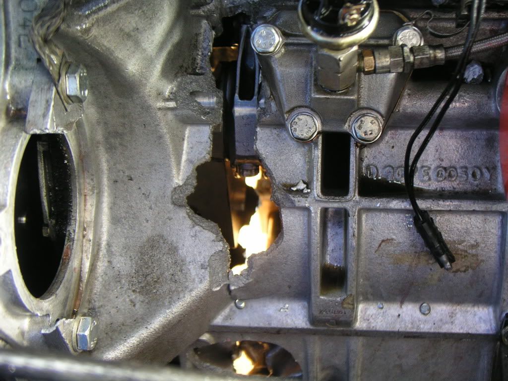 Both the BMW V8 and the Volvo straight 6 in comparison are very reliable and extremely inexpensive, and yet still have a lot of untapped potential....  |
| |
|
|
|
|
|
Jan 12, 2014 15:02:31 GMT
|
I haven't been making very good progress recently as I've been suffereing with an annoying chest cough that seems to have been going around here recently and is proving difficult to shake off. After being out in the garage for less than two hours I had to come back into the house, coughing and wheezing like an old steam train. Anyway, a Mercedes compressor outlet m,anifold that I bought thinking it might be useful turned out not to be when its fgixing centres turned out to be at 95mm square centres and not the 125mm centres that I had asked to be confirmed by the seller. It wasn't expensive though, so I will keep it as it might be useful for cutting up and altering a little later on...  As the latest idea is to use a front mounted intercooler, a single outlet manifold design is more suitable than the dual outlet Jaguar V8 version. A Jaguar XKR6 version might be more suitable as a starting point, but I thought that I might as well just make my own from scratch. The inlet manifold would have to be a special to clear the starter motor in any case. I cut the flanges from some 6mm aluminium alloy plate and roughed-out their openings to suit....  The hole in the outlet flange was cut to match the air discharge area at the rotors but made a little larger to include the small slots that lie outwith of the main opening in the compressor casing. This photo is a little out of focus, but it shows the basic idea....  It won't be finished further until the rest of the outlet pipe has been welded on. The inlet flange has very little material at the ends between the fixings and the gasket mating faces or the port. After cutting this plate I thought that I'd have been better making it a bit longer. I dare say that once the rest of it is added it will be fine, otherwise it might end up being done again but in stainless steel next time...  Both new flanges on the blower. By now though I was coughing constantly and had to call a halt to any thoughts of further progress. After suffering weeks of this I think a (rare for me) visit to the doctor is on the cards during the week.....  |
| |
|
|
|
|
|
Jan 13, 2014 16:55:29 GMT
|
|
Hope the flu improves, are you planning on keeping the cylinder pairings on new manifolds for the M62 or going 4-into-1? (& interesting how they got 80bhp/L from the S62B50 with very similar looking tight manifolds)
|
| |
|
|
|
|
|
Jan 13, 2014 21:41:49 GMT
|
Thanks Sam, every time the cough seems to be improving I go out to the garage and end up coming back in rasping and spluttering after about an hour. I noticed that on the 400bhp M5 version of the M62 V8 all of the exhaust manifolds are exactly the same as the normal type except the really bad ones for cylinders Nos. 1 and 3, which have been replaced with a much better shaped single wall one. I don't have this space restriction on the Sunbeam installation at all, so I had another solution. For my needs with a fairly stock engine, I thought that the stock manifolds would be adequate at least for the time being, but that the really poor cylinders 1 and 3 part just wasn't acceptable. Even though I won't be using any catalytic convertors, I also thought that keeping the double wall manifolds might be good in helping to keep underbonnet heat down considering how close they could end up running to some of the panels and other parts. On the nearside then, I kept the first parts of the manifolds close to the head flanges but had to cut them off at that point as beyond here they would have run straight into the bulkhead. I used parts of the original manifold pipes to point these more directly downwards just ahead of the starter motor and then bend horizontally again under the floorpan. This is how they were after the first cuts were made...  On the offside I took a different approach, and as you point out the cylinder connection order is different side to side due to the cross plane crankshaft firing order. This means that at some point the manifold for cylinders 1 and 3 would have to cross that of cylinders 2 and 4. Although there is no starter motor to avoid on this side of the engine, the bulkhead is slightly further forward due to the pedal box being behind it at this point, and the steering linkage is also crossing the area where the exhaust manifolds would want to be run. By the sound of it though, there was still a bit more space here than on the Capri. I thought about possibly using a second inverted and modified cylinder 2 and 4 manifold for cylinders 1 and 3, but instead I ended up using part of an offside manifold from the L233 Range Rover that uses the same engine. This photo shows the one-piece Range Rover manifold on the bottom with the standard two-piece 540i/740i manifold above it....  I then cut up the Range Rover part to separate off the two primary parts. The photo below shows the normal BMW manifold fitted to the engine on the top and the Range Rover part below it. I'm holding up the Range Rover cylinders 2 and 4 piece which itself has a 'ding' to clear something... but nowhere near as restrictive as the original BMW parts...  I then altered the original cylinders 2 and 4 manifold to clear the bulkhead in a similar way to as on the nearside manifolds. This photo shows the modified part on the bottom with a standard version above it. The idea here again beiong to try to keep the look of the standard factory parts, but made to fit the new installation and also remove the worst of the restrictions...  Here is the same part fitted to the engine as I started to rework the Range Rover part to fit below it...  It was actually quite tricky to do this while retaining the twin wall design, and at one point I began to wonder if I was doing the right thing. I don't know if you have ever cut one of these up, but the inner tubes incorporate a number of slip joints to allow for expansion of the stainless steel material....  Here I'm holding up the end of the other piece that forms the slip joint...  ......and here the two inner piupes are slipped together....  Starting to form the outer wall...  And both sections in the rough awaiting completion and final finishing...  Anyway, that is how I did it, not the easiest solution though and I'm not certain that I'd do it the same way if ever doing it again. I just realised that it might be a little confusing jumping between two simultaneous projects featuring very similar cars but with very different drivetrains in the same thread! |
| |
Last Edit: Jan 13, 2014 21:57:52 GMT by turbeam
|
|
|
|
|
Jan 15, 2014 18:32:03 GMT
|
Just to give a rough idea of my plans for the BMW V8 powered car and to help avoid any possible confusion I thought I'd better give some details on it. It is another Sunbeam, but was originally a Series 2 car in Moonstone Blue. I much prefer the look of the Series 1 cars, most easily identified by having the smaller slightly recessed headlights and mirrors mounted on the door skin rather than at the front edge of the glass. My target is for it to be as close as possible to the standard external appearance of a Series 1 Sunbeam Lotus. For those who aren't familiar with these cars, here is a photograph of an artist impression print I bought of the car complete with its correct registration number....  ....and here are some publicity photos of the standard car.....  ...and for comparison, this is what they normally look like under the bonnet....  In addition to the BMW M62B44 engine, 540i radiator and matching 6-speed Getrag M5 gearbox, this car will also use a Volvo axle modified to carry the standard Sunbeam 4-link arrangement and fitted with an Eaton G80 locking differential, but this time it will be the narrower 1031 casing and half shafts so that the shell doesn't need to be arched. Of course, none of that will be visible with the bonnet down. Although this one will be used as a normal roadcar, for several reasons its standard wheels are not really going to be very suitable. 1) They are only 13" diameter and would result in a very low included final drive ratio. 2) They are only of 6" width and not really able to carry the sort of tyres even in this diameter that I'd have wanted to fit. 3) They would not allow the fitment of front brakes of the size I want to use. I therefore bought a number of Minilite type wheels for it in 15 x 8" size all round, which are a common replacement choice on Sunbeams and similar in appearance to what the works cars had fitted...  I want to keep my options open and allow for a possible quick change of character though. I also like the look of the original 5-spoke 15" revolutions on these cars....  ...so I bought a pair of 15 x 8" ones for the front and am planning on buying some 15 x 9" for the rear later.....I'm not sure whether to keep them all silver or with black centres and polished rims though...  I haven't yet finalised the front disc type that I'm going to use, but I will be using these alloy 4-piston Brembos from the BMW 740i to bite on them....  ...which will be opetated via this Lockheed remote servo as there is no space for the stock servo due to the offside cylinder head. The stock LHD Sunbeam Lotus used two small underbonnet remote servos so it isn't out of keeping, but with rear discs there is probably no need for a servo on the rear circuit? I'll soon find out....  The only other major departure from standard specification is in the interior. The stock shark grey fabric material on the seats was quite badly soiled, faded and stretched and a retrim would have been in order. A good quality job of this type on the full interior would not be cheap! Also, some people like it and some don't, but I really fancied grey leather upholstery...... which would be even more expensive to have done. After a bit of thought I had a brainwave..... the stock BMW M3 seats are very similar in size and design to the original Sunbeam Lotus ones and are available in Titan Grey which is a very close match to the original unfaded colour of the Sunbeam interior.... which is leather! £200+ postage won me a full M3 interior in as-new condition on Ebay including the door cards.... bargain! Here is the sorry looking original Sunbeam Lotus front seat next to the M3 version. Note that the pvc section on the bottom of the seat has faded much less than the fabric material and is a reasonable match to the M3 leather.....  As a bonus they are also more supportive, more adjustable and more comfortable than the original seats. I will be altering the rear sections to suit the Sunbeam so that I can install the full matching leather interior....  So, it should look very like a stock Series 1 Sunbeam Lotus when complete, but be just a little bit more comfortable and luxurious as well having exactly twice the power and torque of the stock original drivetrain, but with better overall fuel economy, much better reliability, and lower parts and service item costs and better availability. It should also sound quite nice without any catalytic convertors, if not exactly the same as the standard car. It isn't to everyones taste and sometimes even the idea of it causes a little upset or even offense to the purists, (particularly Sunbeam Lotus owners), but there is at least some sense in doing it? |
| |
|
|
|
|
|
Jan 18, 2014 16:13:48 GMT
|
I've been doing some research on the engine management side of things for use with the supercharged Volvo B6304 engine over the last few days. I had been thinking along the lines of going Megasquirt for about the last two years, but I'm getting some very mixed feedback from people who have actually used it in the past that is making me just a little wary of going down this route. Apparently though, from what some of the Scandanavian tuners are telling me, the stock Bosch Motronic 1.8 system (MAF metering) is physically capable of measuring additional airflow and metering additional fuel up to about 12psi of boost, which would be plenty for my immediate needs. Beyond that a larger diameter airflow meter and larger injectors could be used to take things a little further. This is really persuading me to stick with the stock Motronic ECU and use a piggyback ECU to retard the ignition timing as necessary as well as fine tuning the fueling requirements. I'm now thinking of going for something like this.... www.ebay.co.uk/itm/141164322267?ssPageName=STRK:MEWAX:IT&_trksid=p3984.m1438.l2648...and fitting one of these to allow it to be set up... www.ebay.co.uk/itm/300976513214?ssPageName=STRK:MEWAX:IT&_trksid=p3984.m1438.l2648....along with some 'light blue' top or red top injectors (as used on the BMW V8) to help keep the fuel pressure and pulse width requirements down. It is apparently possible that I wouldn't even need to install a rising rate fuel pressure regulator as I had been expecting to have to do. This is probably the least expensive, simplest and most effective way of meeting the engines new fuelling and ignition needs when supercharged while still keeping it'safe'. Time will tell, but for now I can press on with completing the REAL hardware. |
| |
|
|
froggy
Posted a lot
Posts: 1,099
|
|
Jan 18, 2014 20:22:59 GMT
|
|
i went with an m-tech ecu which is basically ms3 but built in a factory to use on my lexus v8 rod and its a nice simple system with map/ tps . ive been using the trionic t5 suite to map saab ecus for the last few years but its well supported and i can log and generate a/f maps and datalog plus live map via a can /bus lead .
ive helped a mate do a turbo vr6 with microsquirt and the only issues we had was relocating the crank sensor wire away from the rest of the loom and getting the idle valve to behave but there is so much help online we sorted the issues pretty easily .
i bought the tuner studio software and the phone app so i can bluetooth live data and log on my phone ,base map for the v8 took about 20mins once we calibrated the cts tps and ait ,il be running the motor on the floor in the next couple of weeks .
|
| |
|
|
|
|
|
Jan 18, 2014 21:27:27 GMT
|
|
I know a few people who swear by the MS2 and MS3 systems, and in truth that may well be the way I eventually go on at least one of my cars. I also believe that they will be pretty reliable in the surface mounted component types or when properly assembled in through-board soldered form.
Even some of those who are most enthusiastic about them do say that although there is a huge amount of info and help online for them, it can also involve a huge amount of reading!
I don't yet know if I will be successful in this, but I'm trying to get the supercharged Volvo engine running and installed in the car by late spring/ early summer, and I really don't see this happening if I opted to switch over to Megasquirt at this time. I'd also like to retain the coil on plug arrangement which makes things just a little more involved.
The big advantage to switching over to Megasquirt or similar would be that I could also raise the RPM limit, which could easily go up by 1000rpm on this engine and is still being conservative.
At this point, a piggy back ECU that can affect timing retard control and permit fine tuning of the fuelling via the stock Motronic ECU just seems to require much less time and effort for my immediate goals.
On the BMW V8 I'm having trouble making any headway with its post'96 Motronic system with deep security system integration, which I imagine would also have been an issue with the Lexus V8. In its case it is very likely that I'll eventually have to bin the whole lot and switch to something simpler like Megasquirt to get the job done, but I'd also like to keep its stock coil on plug arrangement, which makes it expensive to accomplish.
|
| |
|
|
|
|
|
|
|
|
Did you get the complete loom to go with the bmw v8? How close are you to buckinghamshire?
|
| |
1988 Mercedes w124 superturbo diesel 508hp
1996 Mercedes s124 e300 diesel wagon
1990 BMW E30 V8 M60 powered!
1999 BMW E46 323ci project car
|
|
|
|
|
Jan 19, 2014 12:37:41 GMT
|
Did you get the complete loom to go with the bmw v8? How close are you to buckinghamshire? I got the complete loom with both of my BMW V8s, all of the normal engine sensors and actuators etc, and the stock Motronic ECU with one of them. I didn't get the transponder key, ignition barrel antenna, receiver/ coding interfacre module or any of the other parts that are normally needed to get the ECU to run the engine. I have heard that some of the drift guys who use these engines have been able to reverse engineer and modify these ECUs to allow them to run on their own, but I haven't as yet been able to find any details on this. As my engine is going to remain almost completely stock it would have been nice if I could have used the original factory ECU, but the security code integration seems to be very deeply embedded into the units design on purpose, details on it are almost non-existant, and this kind of thing is generally well outside of my ability to understand at a PCB level anyway. I have even considered switching to the earlier Motronic system as used on the M60 equipped cars that aren't so tied into the cars security system, and at least I have been able to find pin-out and wiring diagrams for this version. I'm a long way from Buckinghamshire, based in west central Scotland. You sound as if you have experience of doing something similar along these lines? |
| |
|
|
|
|