|
|
|
Dec 27, 2013 11:04:56 GMT
|
Can anyone tell me in what way the core design or dimensions of one of these chargecoolers differ from a normal heater/ oil cooler matrix...preferably with a photo or two? According to what I've read over the years my LC charge cooler which is remarkably compact drops intake temps from 120 deg to 60 deg at 0.7 bar of boost - from what I've gathered it's a doubled up version of the Lotus Esprit turbo charge cooler The radiator to cool the chargecooler fluid is a modified AC rad as far as I know (space was a bit tight) It was years ago on another forum but a member cut up a charge cooler in order to repair it and I'm stuggling to find the pics Yes, that I think is the promise of using a charge cooler. If it is designer for the job it SHOULD work quite well and keep the intake volume down enough to let me mount the throttle body upstream of the supercharger. I'd really like to get a look at one of these cores as I'm less than confident that a heater matrix or oil cooler would work adequately well for this purpose. Using an A/C radiator for the heat dissipation side could be a good idea too, and I should have enough space ahead of the cooling system radiator for mounting one. The small coolant pipes are also very easy to run between the two main parts. A friend of mine has also suggested using a normal air-air intercooler mounted next to the manifold, above the supercharger, and enclosing it in in a plenum/ duct that can be force fed with ambient air for cooling. I think this might be a better idea than front mounting an intercooler and having very long pipe runs. It could have been a really good idea if I were prepared to cut a hole in the bonnet for a vent or scoop, but I really don't want to do that either as I want to keep the stock Group 4 appearance of the car. This indecision is now really holding up this project, and it is pretty much in limbo until I have resolved it and am able to start building parts again. I think I'll have to take another serious look at the XJ6R chargecooler..... The danger is now that I could end up running out of 'winter' time to get it all in place in time for use next year. |
| |
|
|
|
|
|
|
|
Dec 27, 2013 13:07:42 GMT
|
Thanks to Froggy, I think I my have just found the answer to this problem. With the simple addition of a secondary throttle valve upstream of the supercharger, I think that most of the disadvantages and added complexity of using a front mounted intercooler can be neatly side stepped. The revised schematic sketch would be something like this......  The main throttle valve remaining on the intake manifold gives a minimum plenum volume and a crisp vacuum signal. The second throttle body cuts the airflow to the supercharger, so the flow requirements of the bypass valve are greatly reduced as well as the parasitic drive losses of the supercharger being minimised with its load reduced. With the secondary throttle being just upstream of it, this should also give a crisp demand at the airflow meter without any column inertia effects of the intake air in the system. I'm thinking along the lines that if the secondary throttle was to close just a fraction behind/ less than the main throttle, there would always be a small amount of pressure in the whole system that would be ready to act the instant that the primary throttle opened, but it would be low enough in flow rate to be able to be bypassed by a regular recirculatory type bypass valve. I'm beginning to think that this idea may bias my choice in favour of using a normal front mounted air-air intercooler? EDIT, I'm now just weighing up the pros and cons of having the bypass valve pipe returning either upstream or downstream of the secondary throttle valve........any thoughts? |
| |
Last Edit: Dec 27, 2013 13:14:03 GMT by turbeam
|
|
froggy
Posted a lot

Posts: 1,099
|
|
Dec 27, 2013 22:31:40 GMT
|
|
Bypass needs to be plumbed in before the s/c throttle so it can supply air for idle and have the s/c throttle fully shut .
Bypassing after the s/c throttke will send the air through the charger until the throttke opens again .
|
| |
|
|
|
|
|
Dec 28, 2013 12:42:19 GMT
|
Bypass needs to be plumbed in before the s/c throttle (UPSTREAM of it) so it can supply air for idle and have the s/c throttle fully shut . Bypassing after the s/c throttle (DOWNSTREAM of it) will send the air through the charger until the throttle opens again . Yes, these are exactly the options I'm weighing up right now. I've added a couple of descriptive terms to the quote above just for clarity purposes, which I think is what you meant? I'm currently using a stock MAF, but when this system is up and running properly it will most likely be with a manifold absolute pressure sensor and a speed/ density type management system. As shown in the sketch, the bypassed air obviously has to be returned downstream of any airflow meter or the intake air will be measured more than once. Beyond that, as far as idle air goes, this is done with a completely separate management system controlled idle air valve (not shown), which would (while retaining a MAF) be plumbed in immediately downstream of the airflow meter, and would be completely independant of the main off-idle airflow plumbing. (ie, between the secondary throttle and the MAF in the previous sketch). Neither throttle valve then has any need to remain partially open for idle air requirements. If I'm reading this correctly, while both throttles are fully closed on the other twin throttle equipped systems in use on other cars with the bypass valve open but without a separate idle air valve, if the bypass valve is also used to provide idle air it will be travelling in the reverse direction to any air still being bypassed around the system by the supercharger. Even with the throttle valve fully closed, if there are any leaks at all it could possibly badly disrupt the very low volume idle airflow trying to go the other way. Also, during any transition period between throttle closing and idle, the airflow direction through the bypass valve would have to change over at some point? Anyway, none of this applies where a separate idle control valve is fitted. With idle air requirements right out of the picture then, the bypass air return could be positioned either upstream or downstream of the secondary throttle, and the throttle COULD be closed completely in either case, but with slightly different results. Here are my thoughts on closing the secondary throttle valve:- THROTTLE FULLY CLOSED / UPSTREAM BYPASSING If the throttle is closed completely and air is bypassed upstream of it, the supercharger will have its intake air supply completely cut off. From the data I've seen from Eaton, when the supercharger intake and output pressures are equal and it is running at a near zero pressure ratio, there are very small power losses involved in driving these units that are mainly from friction in the drive system itself. Closing the throttle completely would likely result in the unit trying to create a partial vacuum between itself and the throttle valve though, and I'm not sure if this would affect the power absorbed in driving it or not? I don't think you can expect to create a pressure difference, even a negative pressure, without using some power to do it? I'm not sure therefore if it would be better to leave the throttle slightly open for this reason, and/or keep the pressure difference across the supercharger lower to reduce power loss, not unlike how the supercharger is bypassed completely in the VW system diagram we saw earlier elsewhere. In either case, the total power absorbed in driving the 'charger like this is likely to be quite small. More importantly in my opinion though are the effects that rapidly closing the secondary throttles would have on the inertia of the total volume of air in the system between the throttles. I realise that as well as the engine trying to draw in air that the supercharger will also be pumping it from the other end when both throttlers are opened again, but the whole point of this is to allow use of a front mounted intercooler which also requires long runs of fairly large diameter pipes which will contain a large volume of air with a good deal of inertia. If in addition to minimising the pressure fluctuations at the supercharger itself a small amount of airflow could be circulated around the intercooler plumbing circuit during closed throttle conditions I can see some advantages. Also, in the period immediately following closure of the secondary throttle, if the throttle is completely closed and the bypass air is diverted upstream of it, there is a good chance that the momentum of some of this air could possibly cause it to make a second reversed and third forward pass through the airflow meter giving a false fueling signal. Again, not a problem if no MAF meter is involved. THROTTLE FULLY CLOSED / DOWNSTREAM BYPASSING In this case, all bypass air is recirculated through the supercharger and right through the intercooler plumbing circuit. Even with sudden throttle closure at high engine rpm the total flow would be quite low as it will be restricted by the size of the bypass valve and its pipes. There should be very little or no negative pressure being produced upstream of the supercharger though, and a reduced amount of airflow inertia effect in the rest of the system. The greater the bypass circuit capacity, the greater the airflow around the whole supercharger and intercooler plumbing circuit. None of the recirculated air should be able to get back upstream as far as the airflow meter. (where one is fitted). If the secondary throttle is closed fully at the same time as the primary throttle, even when the air in this circuit is only being recirculated it should I think retain the residual pressure that was present at the time that the throttles were closed (barring any system leaks of course). SECONDARY THROTTLE LEFT FRACTIONALLY OPEN WHEN PRIMARY CLOSED / UPSTREAM BYPASSING Here, it could be arranged that when the primary throttle valve at the intake manifold is completely closed the secondary throttle remained open just a whisker. If the bypass route was sized and opened to suit, a small residual positive pressure could be maintained in the intercooler plumbing circuit, this time topped up by fresh intake air. With enough bypassing capacity it could also (as with previous downstream bypassing) give significant amounts of airflow around the circuit and through the intercooler core.... the supercharger would add very little heat to the intake air in doing this but the intercooler could take a lot of it back out. (only maintaining pressure rather than creating it). None of the above options would involve any real extra work over another, and other than the size of the bypass valve/s used would be equally easy to put in place. Again, any thoughts or opinions on any of this, whether anyone has actually tried it or not, are much appreciated. Bouncing ideas around like this could help rule out any obvious non-starters or highlight any points that I've overlooked. I have no personal experience of any of these, and as any system has to be built before it can be tested I'd rather avoid wasting time going up any blind alleys or buying wrong or unnecessary parts if possible. Cheers, Jim |
| |
|
|
froggy
Posted a lot
Posts: 1,099
|
|
Dec 28, 2013 17:54:15 GMT
|
|
Does the m112 have a bypass built into the case ?
|
| |
|
|
|
|
|
Dec 29, 2013 10:30:53 GMT
|
|
The M112 doesn't have any bypassing built directly into the casing. The normal compressor intake manifold (on the rear face of the 'charger) as fitted to the XKR8 does have a very small poppet-valve type of bypass valve, but I don't have one of these manifolds as it wouldn't have cleared my starter motor in the position I've mounted it on the engine.
As I will have to make some kind of compact U-shaped replacement manifold to turn the plumbing back around towards the front of the car to avoid the starter motor (and by current thinking now also to mount a secondary throttle valve onto it) the compressor bypass valve could probably be located in a position where the compressor intake ducting and inlet manifold plumbing are passing very close to each other.
Depending on which arrangement I decide to try out, I could use another throttle body type butterfly valve controlled by something like a wastegate actuator to open it using plenum vacuum?
I'm sure countless numbers of people will have been over this ground in the past, and if I can draw on some of that experience it could save me a lot of time consuming trial and error.
I'm really just trying to come up with a temporary system that is as simple as possible and which hopefully will work reasonably well straight out of the box.
In the meantime, as it is now looking more likely that I'll be using the large front mounted intercooler, I can at least get on with fabricating some of the brackets and new cooling airflow ducting parts for it.
|
| |
|
|
froggy
Posted a lot
Posts: 1,099
|
|
Dec 29, 2013 11:32:50 GMT
|
Simplest solution is fit a mini s/c bypass after the s/c throttle then use a normal piston dv next to the plenum throttle linked to the front side of the s/c throttle . That way you can go to map/Tps management with no changes and that's how I plumbed mine before building a chargecooled manifold and using a single pre charger throttle . That way you have vac control of the charger and a big enough bypass to stop the charger doing any wasted work in partial throttle conditions as the piston dv will be open as well as the s/c bypass . Response will be more related to gearing of the charger at low rpm . I ran an m62 at 8psi on my 2.0 twin charged set up so I got some torque below 2000 rpm but its just like a turbo you can't have it both ways if you gear it too low you will suffer with heat issues at the top end . I had to run meth with a single chargecooled inlet as the charger heat soaked pretty quickly once my Holset started making some boost but it could flow the cfm needed to make 400hp at 10 psi with the massive exhaust housing letting it cope with 30 psi at the manifold .  You can just make it out as its quite a compact unit  |
| |
Last Edit: Dec 29, 2013 11:42:13 GMT by froggy
|
|
|
|
|
Dec 29, 2013 12:07:33 GMT
|
|
|
| |
|
|
|
|
|
Dec 29, 2013 20:58:09 GMT
|
Cheers guys, Froggy, the Mini bypass valve is pretty much what I was thinking about, and I'm watching one on Ebay at the moment. Again just for clarity, I've redrawn my earlier schematic sketch along the lines that you have suggested to include a Mini bypass valve. I'm not sure that I follow exactly how you controlled the dump valve you used. If I'm reading it right, you took a vacuum signal for it from downstream of the secondary throttle valve (as shown by the broken line) and just vented it to atmosphere, or did you mean that you recirculated it back into the system just downstream of the secondary throttle......  My original idea was also to use a single throttle and a charge cooler, but on my tight installation it would barely be possible to do. The twin throttle idea has moved the goalposts for me and made normal intercooler a more realistic proposition. On the gearing of the drive, as the M112 is probably already a bit on the big side for my engine I certainly won't be further overdriving it with a bigger crankshaft sprocket as is commonly done on the XKR8. I had thought about possibly even reducing the drive ratio a little from the stock Jaguar design ratio, but I'm now thinking that I will leave it more or less the same even though my engine is only 3/4 of the capacity of the Jag engine but is a bit more performance orientated. I'd agree, I think the real benefit of adding a supercharger as far as the turbo goes is that it allows its size to be biased far more towards upper rpm operation, which in turn frees up the exhaust with a larger hotside and allows its power to be produced more easily and with greater efficiency. If I was ever to consider compound charging, I think I'd have to upsize my current turbos to take advantage of this, but I'm not sure that I could fit any that were much physically bigger into this little car! Claymore, your bypass route there looks to be ideal. On the Eaton M112 the whole air entry section that is integral with your charger is a separate bolt-on manifold, which is just as well since if it was integral like yours it wouldn't fit on my engine without even more mutilation and surgery. As of today, I decided that I will definitely be using a front mounted intercooler rather than a charge cooler. I spent most of the day just thinking through this plan, and have decided that I can make a much better arrangement of the pipework and general layout if I reposition the supercharger. So in short I have torn all of the new brackets etc back off of the engine and have just started to make new ones that this time will support the supercharger in a side-on (vertical rotor centres) position against the block rather than sitting horizontally as it was. Doing this appears to give a number of advantages in plumbing and manifolding, as well as leaving a bit more space around the starter motor and alternator. A big advantage is that it will allow the compressor outlet manifold to point directly forward below the thermostat housing and around the front of the engine to the intercooler giving a much shorter pipe run. If all goes well tomorrow I should get the basic mounting brackets made up and can then show the unit in its new orientation. |
| |
|
|
froggy
Posted a lot
Posts: 1,099
|
|
Dec 30, 2013 11:12:09 GMT
|
|
i would have the dv drawing air from the front side of the s/c throttle so it can be 100%shut in vac conditions .
|
| |
|
|
|
|
|
|
|
Dec 31, 2013 11:33:10 GMT
|
i would have the dv drawing air from the front side of the s/c throttle so it can be 100%shut in vac conditions . OK, It isn't very clear in the sketch, but the secondary throttle would be fully closed there at the same time as the primary throttle is also fully closed. I was thinking that the DV would allow the intake air to recirculate around all of the plumbing in the circuit between the two throttles, with the Mini bypass valve operating at the same time to prevent it being recompressed in the supercharger. So, bearing in mind that I will have a completely independant idle air circuit on my engine, you would take the DV return back upstream of the secondary throttle instead, and I think take a vaccuum signal for it from just downstream of the secondary throttle? The only thing I'm thinking here is that as the primary throttle would also be fully closed, (unlike in the original Mini layout) there would be no engine intake vacuum acting on any of this part of the system, and only any vacuum generated between the supercharger and the fully closed secondary throttle would be available to operate either the Mini bypass or the DV valve if connected to this part of the system? If the Mini bypass valve is then opened to prevent a vacuum upstream of the supercharger and reduce its losses, the vac signal to both would be lost? I was thinking about altering the Mini bypass valves vac line so that both it and the DV valve could be opened by engine vacuum when their vac lines are connected to the intake plenum instead. Recirculating the return air ahead (upstream of) the supercharger would help to keep the pressure each side of the supercharger more equal and reduce its loading? Sorry if I'm not picking you up correctly on this, by 'front side' I'm assuming that you meant upstream of the secondary throttle? |
| |
|
|
|
|
|
Dec 31, 2013 12:41:07 GMT
|
After deciding that on balance normal air/air intercooling was probably the best way forward, I basically went right back to the drawing board and had a complete rethink on the supercharger installation. In fact over the last few days I've done much more thinking than fabrication. The end result is that I've now abandoned all of the brackets and parts that had been made up until now and have started afresh, this time with the supercharger mounted side-on with its rotor centres positioned vertically, or at least almost vertically as it will be fixed tight to the engine block which itself is slightly inclined towards the offside. This might be a bit of a backward step, but it will eventually give a much better installation not only on the inrtake air pipework runs but also on improved positioning for the intake manifold, starter motor, nearside engine mounting bracket, alternator and the oil cooler take-off. The new supercharger brackets are a good bit simpler than the ones they replace, shown here in early mock up form.....  The front one will also be useful for fixings for the drive belt tensioner pulley mounting bracket a little later on. Here the drive belt run is being checked once the supercharger has been fixed plumb and square to the block...  ...which gets the supercharger in a more ideal position than before...  ....that is also considerably more compact.....  In this position, I think a Jaguar XJR6 compressor outlet casting would be a better starting point than the XKR8 one fitted here as it would allow the alternator to be positioned slightly higher up. I'll have to check that this part has the same 125mm centres dimension between its fixings as the XKR8 version does....  Sometimes you have to take a step backwards to move forwards, but I'm starting to wonder if I'll have enough time left to get where I want to with this project before April? |
| |
|
|
froggy
Posted a lot
Posts: 1,099
|
|
Dec 31, 2013 19:10:32 GMT
|
|
The vac for the comp bypass should be from the plenum the same as the dv .
|
| |
|
|
|
|
|
Dec 31, 2013 19:43:09 GMT
|
Thanks Froggy, that was what I was thinking. I think I'll try it initially with the DV returning its air just downstream of the secondary throttle as shown in the sketch though rather than upstream of it. I've stopped a bit earlier tonight so that I can get a clean up before the new year, but I have managed to get the new alternator mounting bracket cobbled together ready for later cleaning up. These brackets will likely play a part in supporting the supercharger drivebelt tensioner or other items, so not much point in fettling them more fully just now. This is how the alternator looks on the engine now, much better positioned than was possible previously....   ...and this one shows how much easier the compressor intake manifold design will be with more clearance at the starter motor in this position.....  Just before I came in for the night I had a quick look at re-using the original inlet manifolds runners in a different order that will better suit the new inlet manifold design....  So, that is the final bit of progress for 2013. A happy new year to everyone when it comes....in about four hours. |
| |
|
|
|
|
|
Dec 31, 2013 20:28:29 GMT
|
I'm using a mini bypass valve on my ginetta.  |
| |
|
|
|
|
|
|
|
|
I think I'll most likely be doing the same, either that or using a very similar one from a Mercedes.
I've looked at the XJR6 compressor outlet manifold and although it has a slightly better shape and a single round outlet, I'm not all that keen on either its flange fixings or even all that confident that it is directly compatible.
I'm thinking on taking a chance on a Mercedes version of the manifold that I've seen which will definitely need some alteration and modification anyway but could give a better end result.
Failing that, I will be making the new manifold parts from sheet steel for simplicity.
|
| |
|
|
|
|
|
|
|
|
I've bitten the bullet on the SLK compressor outlet manifold as it appears to have the correct flange fixing pattern for the M112 as was fitted to the XKR8.... that wasn't by any means a certainty as Eaton make their OEM fitment superchargers specifically for each individual application..... in fact, they do not supply their own superchargers to the aftermarket at all, leaving that niche to people like Magnusson etc to make housings etc to accept Eaton rotors.
I've been looking at Mini bypass valves, but in my case with the throttles closed abruptly that big M112 will still be trying to shift a large volume of air around the whole intercooler circuit. Perhaps use a Jaguar valve, or even fit a pair of Mini based bypass circuits in parallel?
The Mini bypass valve looks useful, but it is basically just a normal butterfly valve that is opened by a vacuum capsule, and I'm wondering if I wouldn't be better just to make something up from a larger diameter throttle valve and fit a vacuum capsule to it for its operation. These are quite commonly fitted for use on everything from idle and autotrans control circuits through to cabin heater valve controls.
As I'm in no pressing need for one just yet, I can afford to have a bit of a think about it.
Funnily enough though, the curve and shape of the cast alloy chargecooler pipe on the Mini could be handy for cutting up and use in fabricating a compressor inlet pipe if I decide to make one in aluminium rather than steel.... again, not a pressing issue just yet.
|
| |
|
|
|
|
|
|
|
Despite not really feeling up to it today with a chesty cough and irritated throat, frustration drove me out to the garage regardless and I carried on mocking up the parts for the new inlet manifold. First, all of the individual runner sections had any excess pieces of casting, unnecessary brackets or any remaining parts of the old 960 'octopus' manifold cut off, ground away and blended in. The plenum will be of a long narrow triangular shape that is wider at the front and with the primary throttle body pointing forwards at an angle to clear the compressor outlet pipe. This will also point the intake air at a shallow angle to the runners in the front cylinders to avoid just blowing the total intake airflow straight across their entries. Space for a new longer manifold is still a little bit restrictive ahead of the bulkhead on the passenger side of this little car, and my plan is to run the compressor intake pipe above the inlet manifold, so it must be able to pass behind it next to the bulkhead. For these reasons I wanted to have the rear runners coming forward in order to reduce the overall length of the new intake manifold plenum and pull the runner centres closer together. Also the runner of No.1 cylinder has to bias slightly rearwards to give clearance at the thermostat housing as already mentioned. With this in mind I adapted the original manifold's chopped off runner sections to meet these requirements, which in three cases meant having to extend them towards the plenum position using short straight sections of thick wall aluminium alloy tube. With all of the pieces roughly sat in position in their rubber mountings and the tubular extensions tacked loosely into place it started to look like this....  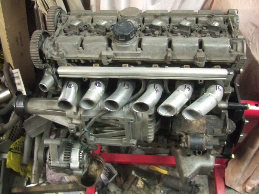  The idea now is to cut a piece of 4mm aluminium plate to form the front wall of the plenum at the runners and then cut six 50mm holes in it at the correct spacing for the inlet runners. I will then make a pair of large radius bellmouthing dies (possibly in steel or even hardwood) to take a through bolt which can be used to pull a nice bellmouth curvature into the aluminium around the holes where it will fit over the runners. The whole plate can then be bent into a slight curve to match the curve of the ends of the runners as the plenum triangular shape tapers down as it nears its rear end. The way I'm feeling right now though this isn't likely to start happening tomorrow! |
| |
|
|
lowen
Part of things
Posts: 47 
|
|
|
|
|
I fitted a bypass pipe on my compounded Land Rover so I could see how different with and without it making boost it is and found it becomes much quieter when opened and the supercharger doesn't do the compressing. For normal road driving I prefer superchargers over turbos as the torque is always there when you want it so it's good to see another charger being fitted.
I've been stuck on how exactly I'm going to cool my compressed air since starting my build but quickly decided I wanted to go down the chargecooler route as plumbing a front mount intercooler didn't appeal and I previously had a top mount intercooler that kept shaking itself off so I'm not a big fan of intercoolers when there are different ways of doing it.
The better heat conduction of water and less silicone joiners sold me on this idea just £800+ for the kit I'm after could buy many more gizmos instead, so I'm going to be trying heater matrix's from either Mini's or Land Rovers as chargecoolers depending on my space and where my new turbo will go. If it works it'll save a fair wadge and if not I'll know why not many have tried it.
I've done some reading up about chargecooled set ups that work and don't work and often have seen the ones that don't work straight away usually don't have the right shape cooler or fluid cooling capacity. The problem I've seen so far with heaters and oil coolers is they are very thin when compared to the likes of bullet chargecoolers and don't allow air much time to give it's heat away, so a couple would need to be used in series as a bigger unit to help solve this or maybe a double pass configuration. I reckon with some careful thinking it would work fairly well for it's lower cost as it can be fabricated to the available space.
Something to think about further down the line when you're under less pressure maybe?
Keep up the great fabrication!
EDIT: I saw in another thread you asked about supercharger outlet plates, mine is made from 6mm 304 stainless with a frosties cardboard gasket and has seen 24psi so far, it probably could have been made from 3mm but it's what I had kicking about.
|
| |
Last Edit: Jan 3, 2014 1:32:15 GMT by lowen
|
|
|
|
|
|
|
|
Hi Lowen93, It sounds like I have been over many of the same options as yourself on many of the issues with compact intake air cooling, and often came to the same conclusions as well.
I will definitely be fitting a compressor bypass valve of some description along the same lines as a Mini one and taking its vacuum signal directly from the intake plenum. Once I see how much space is available for this and other factors I will decide whether to use an actual Mini one or make it myself using a larger diameter throttle body as the valve.... I think with a fast rotating M112 and a rapidly closed throttle/s that I want to get as much bypassing capacity in the system as possible for my use.
I initially thought that chargecooling might be my best option too, but in my case the space around the engine where a chargecooler manifold would have to go (in order to keep the whole thing compact) is very tight, and actually fabricating something to fit in there would be difficult as well as causing some other access problems. It would then still need a front mounted chargecooler radiator (someone suggested using an A/C condenser matrix for this which I thought was a good idea) as well as the water lines, reservoir and a pump.
I also believed that a water/ air heat exchanger would be more efficient, but if you think about it the heat exchange happens twice with chargecooling (air to water followed by water to air) so their efficiencies are multiplied where as intercoolers are only air to air.
Proper aftermarket chargecoolers should work well, but as you also found out they are usually between five and ten times the cost of an equivalent intercooler. Claymores views and experience with the Subaru chargecooler didn't give me much confidence in trying to utilise one of those either, and I didn't really fancy buying one that I would have to cut about to make fit.
Oil cooler and heater matrix elements could be used and both should be up to at least medium boost use, but as you point out they are really both designed for the flow of the medium that you want to be cooled or heated to go in the opposite direction. I don't really think that this presents enough fin area to the intake air during its passage through the matrix to cool the charge sufficiently, and doubling up the cores thickness would add a lot of extra intake restriction and pressure loss.
Another major disadvantage with a home brewed cobbled-together type of chargecooler along the lines that I would have been making is that it it was to develop a water leak for any reason, water could end up going straight into the engine with possible disasterous results.... at least with an intercooler leak, even a major one, you only loose boost pressure.
Basically, as soon as Froggy suggested the dual throttle valve idea earlier it greatly affected my thinking on this. After rejigging my plumbing routing plans I've now been able to get the intercooler pipeing runs much more compact as well as using a relatively large front mounted intercooler for good heat transfer at high airflow rates while still keeping pressure loss to a minimum.
From my previous post you will see that space even for just a normal intake manifold and plenum is a consideration, but at least being able to remove this quickly and easily for maintanance is a big advantage over having the chargecooler in there. Also, the twin turbo arrangement that I made for the car was to use this same intercooler so if I switch between the two systems in future many of these parts, including the new intake manifold, will be common to both arrangements which also has some advantages.
Much of my early thinking with using a chargecooler was in allowing me to prefabricate most of the parts on the dummy engine out of the car so that they could be installed with minimum down-time, but it soon became clear that this wasn't really going to be the case.
On the supercharger outlet manifold plate, I wasn't sure how well these would cope with internal pressure and deflection with only a fixing at each corner especially when the corner at the fixing projects well beyond the edge of the flange. Once the rest of the outlet duct is added it will really stiffen the whole thing up, and in most cases the internal pressure won't be as high as I might have been thinking about either. Also, the flange mating face width on that supercharger is much thicker than the one on mine, which will help give the joint and its gasket an easy time.
Personally, I'd still have used the 6mm plate in your case by choice, but then again I have a general tendancy to over-engineer parts a little bit. On the other hand, it is rare for parts that I've made to fail mechanically....which doesn't always mean that they actually work as intended!
|
| |
|
|
|
|


