Em
Part of things
 Fuel Injected? Carb Infested!
Posts: 601 
|
|
|
|
Cheers for the comments chaps! Ruishy – Woo! A blown Soarer! Cool! Will be keeping an eye on this one! Pingu – Heh heh, sorry dude! You know it’ll be worth it though! Mdh – Cheers Fella! You thinking of Strombergs? I did consider them briefly, but the height problem is sorted now. Just… Valman – Thanks mate! Blimey, first post for exactly a month and a day! Not much progress in the last four weeks, holidays and Glasto have combined to keep me out of the garage. It’s a hard life…  Anyhoo, a few bits and pieces. 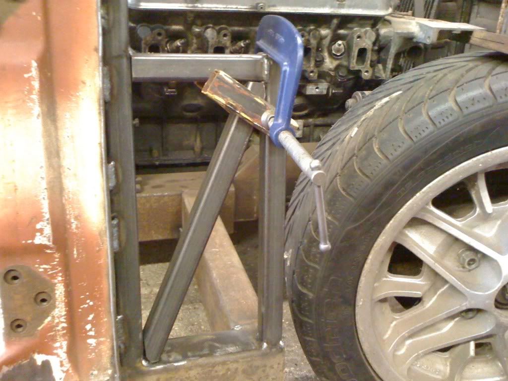 Tacked up the bulkhead bracing and added some triangulation. It’s all just tacked at this stage, I’m that confident of my measuring… 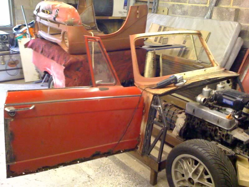 Doors hanging properly for the first time in years! It’s great being able to just swing them aside to get in, instead of picking them up and manhandling them across the garage and stacking them up somewhere inconvenient. 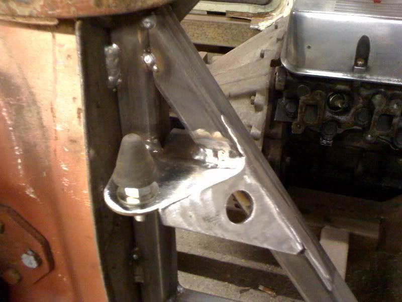 Made up some proper bonnet cone brackets to replace the temporary bits of angle iron I’d tacked on. Now I’ve got the bulkhead sorted(ish) seems a good time to think about mounting the bonnet. 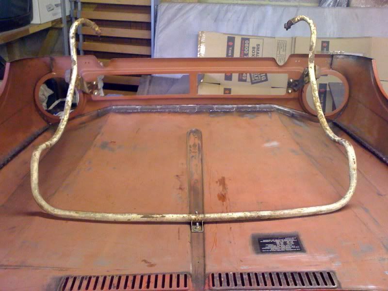 After spending ages drilling out the seized bonnet hinge bolts the frame goes back in together with… 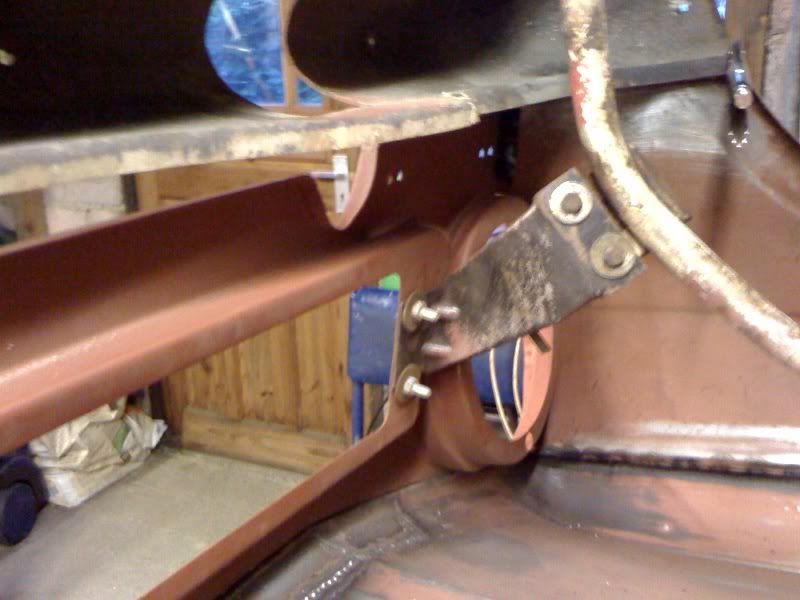 …these support brackets chopped out from the old bonnet. I’ve bolted rather than welded them fro the moment, as I’m undecided whether to use them or fabricate something new and stronger. 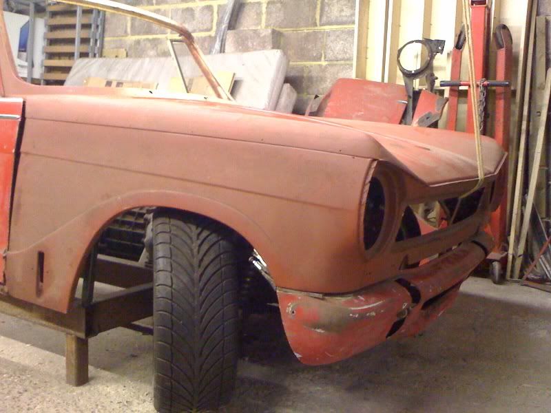 Clamped the valance in place with a couple of spacers to set the gap, and with the bonnet resting on the cones at the back and strung from the garage roof at the front, I can start to see what’s needed. 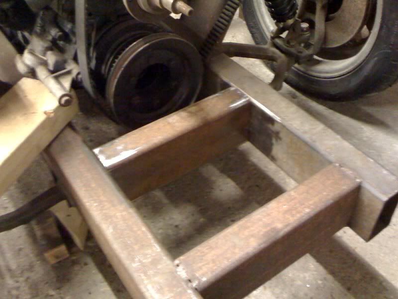 Next step is to weld in a new front crossmember… 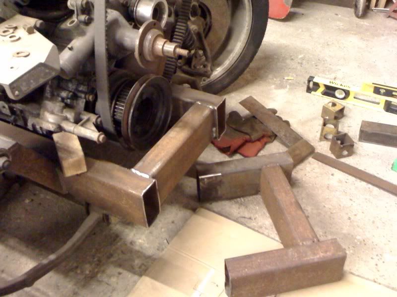 …and lop the front of the chassis down to size. (Made it over-long at the laying out stage, just to be safe…) 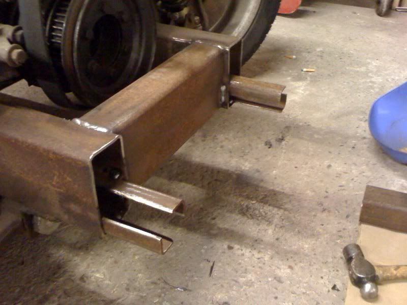 Then welded in these little angle iron extension tabs… 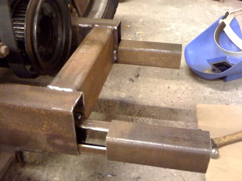 …that mean the front extension can be slid on and off for welding on the bench until I’m happy enough with it to spark it on for good. 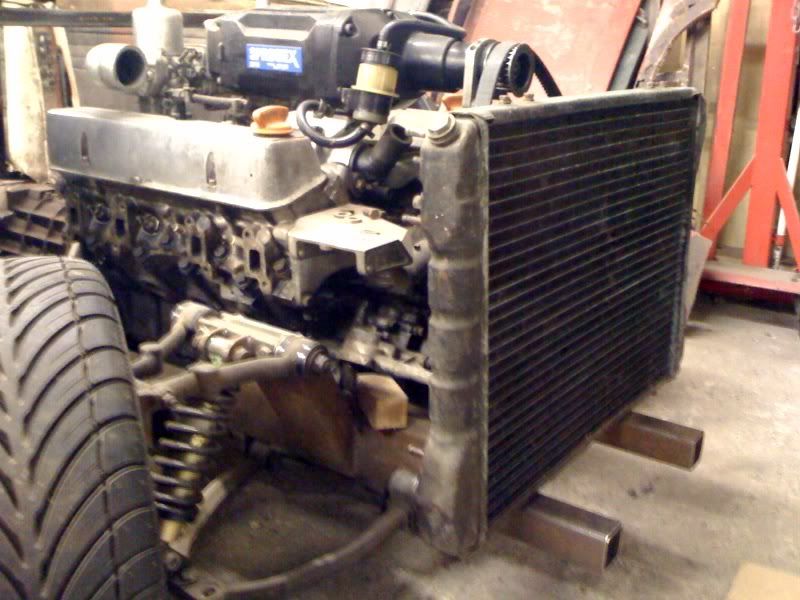 The reason for the little step is to allow space for this rad, culled from an XJ40 if I remember correctly. I hear blown motors take a bit of cooling, I’m taking no chances…! 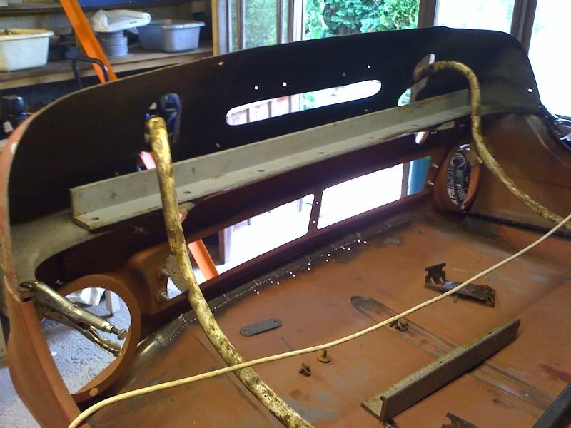 Next step is to fabricate the front spreader bar and incorporate mounts for the oil cooler, bonnet and valence, which may involve this chunk of angle iron or perhaps something less agricultural. We’ll see… Cheers! Em. |
| |
|
|
|
|
|
|
|
Jul 15, 2010 13:12:48 GMT
|
|
Progress, looking good! reminds me I really should do some welding on mine, maby in winter. .
|
| |
|
|
Em
Part of things
Fuel Injected? Carb Infested!
Posts: 601
|
|
Aug 24, 2010 12:11:32 GMT
|
Seems lately the intervals between posts gets longer and longer while the actual content gets shorter and shorter…! Back in the garage after my “summer recess” at long last. Not a great deal to show for the last month or so, but for what it’s worth… 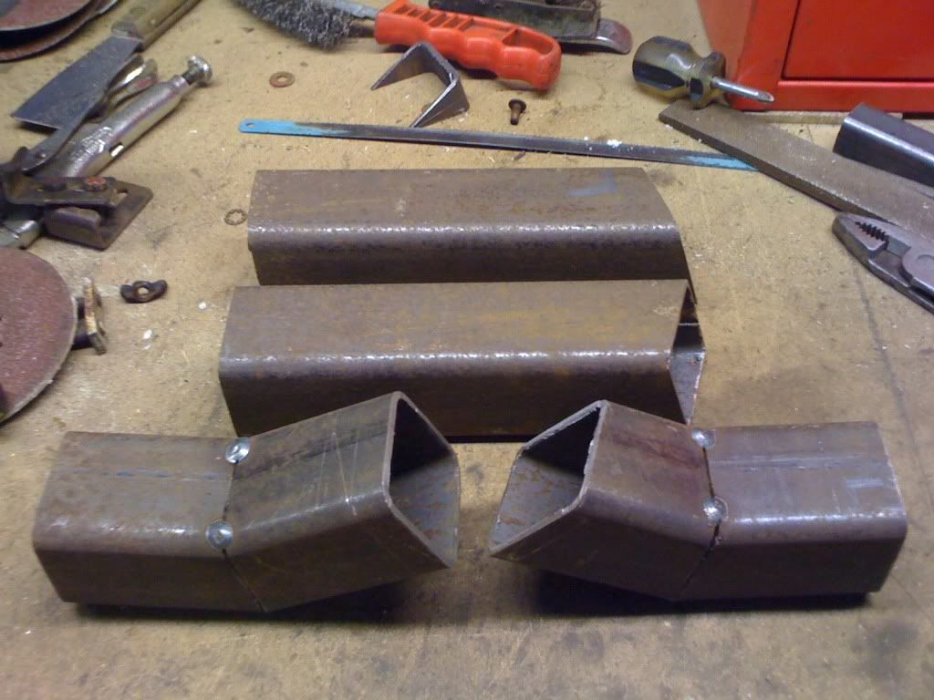 Slid the little sections that are going to hold the bonnet and front valence mounts off their tabs on the chassis and chopped ‘em up. Also cut some slightly longer pieces for them to attach to. Wish I’d taken more notice at school during Geometry lessons; this angle cutting is more complicated than it looks! 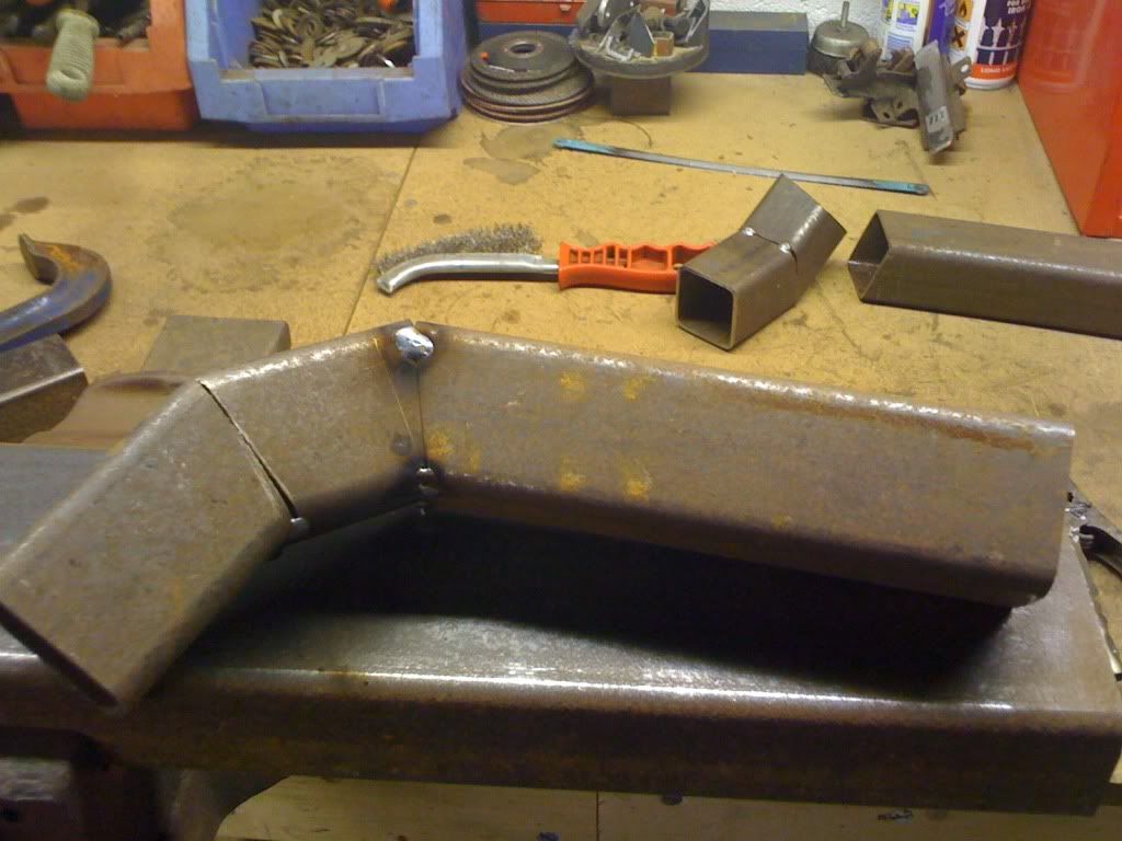 Again, just tacked in place for now. Doesn’t look like there’s much ‘angle’ in it here but it’s more twisty than it looks. 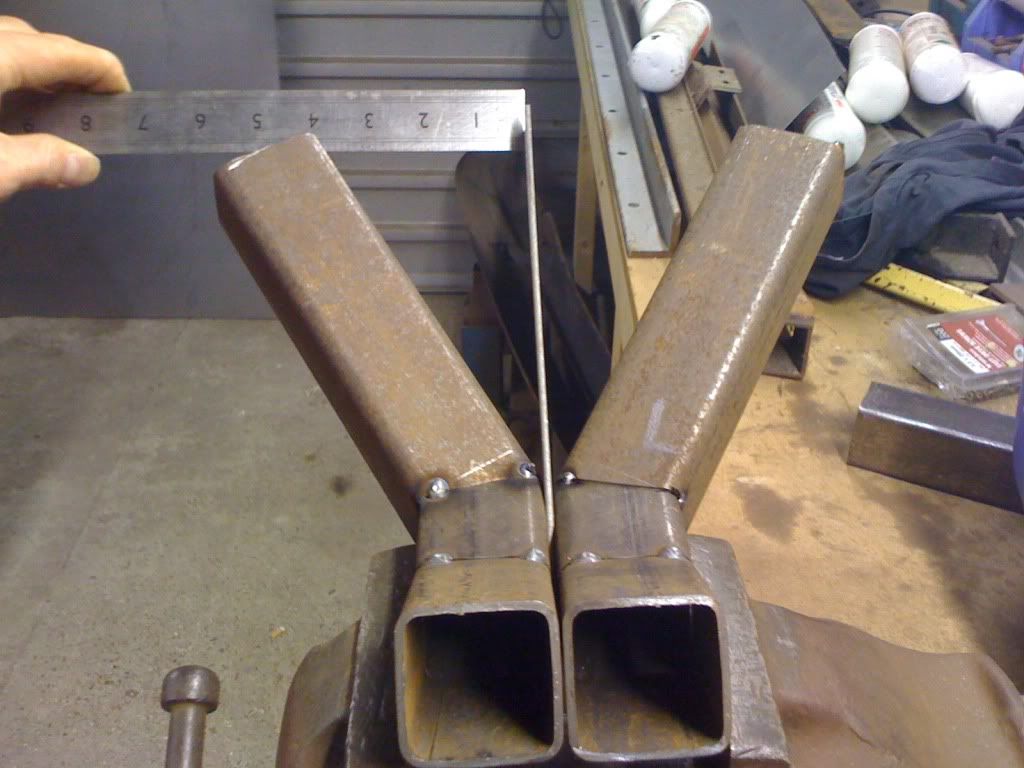 My low-pressison way of checking that they’re both mirror images of each other. Close enough….! 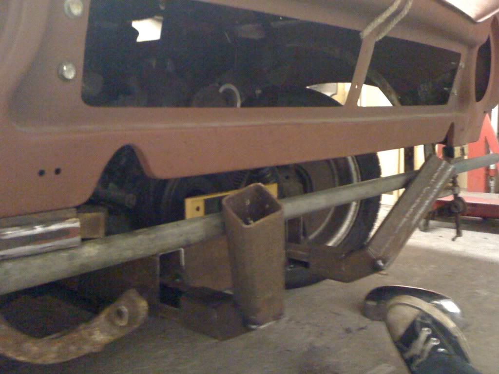 Slid back on their tabs a little way, you can start to see what’s going to happen. The “splay” is to make room for an oil cooler to snuggle up behind the hole in the valence and the round bar clamped under the bonnet isn’t part of the structure, just there to help me measure. If the current rate of progress is anything to go by, expect a meagre two picture update sometime in November. 2012….. Cheers ! Em. |
| |
|
|
|
|
|
Aug 24, 2010 13:07:31 GMT
|
Progress is better than none, at least your plodding on. the front frame really makes sense, altho the problem I've noticed with the front still flipping forwards, altho great for access you can catch you head on the wheel arches. still when its raining it provides a great umbrella to carry out roadside repairs  |
| |
|
|
Em
Part of things
Fuel Injected? Carb Infested!
Posts: 601
|
|
Aug 24, 2010 14:08:53 GMT
|
|
Cheers Mr. Mork! Yup, slow but steady!
Heh heh, yeah, I've bashed my head on the wheel arches more than a few times! It's nice to be able to sit on the wheel and change the plugs though, eh? (Can you still do that with your Rotate-ory powered version, or are the plugs buried somewhere awkward?!)
|
| |
|
|
|
|
|
Aug 24, 2010 14:46:43 GMT
|
|
I can cuddle my engine there is that much space.
Back to it, chop chop mate.
|
| |
|
|
Em
Part of things
Fuel Injected? Carb Infested!
Posts: 601
|
|
Sept 2, 2010 16:41:39 GMT
|
Heh heh, that's brilliant! Right-oh Boss The last (mole)gripping instalment saw me starting to make the front extension of the chassis, to mount the valence and bonnet hinges. 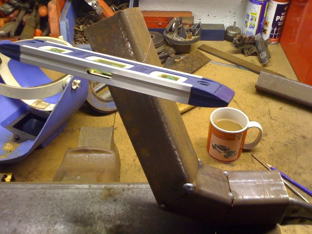 Next it’s time to trim them down to size and hopefully end up with flat, level ends.. 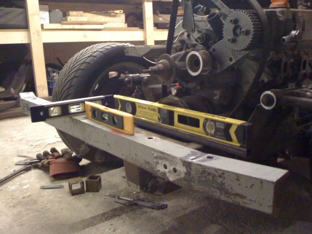 …to mount this rather substantial section of angle iron. This is about 10mm thick and weighs a ton. Reason for the overkill is I’m going to make a rotisserie at some point and the front mount will go on here. Also, it couldn’t hurt in the event of a crash…. Rustled up all my spirit levels prior to tacking it up… 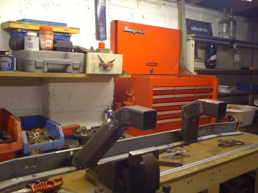 And then pulled it off again to weld it up proper. 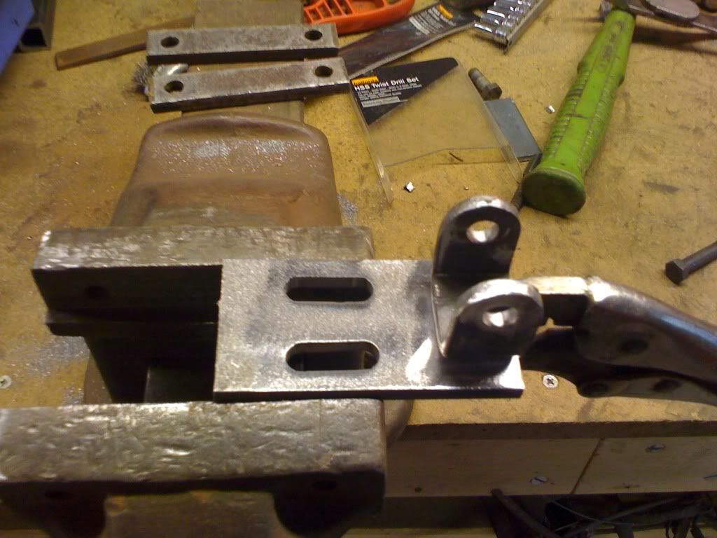 There was no way I was going to use the ridiculously complicated and impossible-to-adjust-correctly standard bonnet hinge arrangement, so I made this. Well I actually made two of them, just having one would be silly. Slots allow for a bit of up and down adjustment, fore and aft will be taken care of by shims. I like shims... 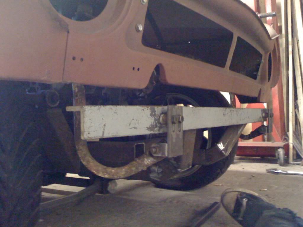 Here they are all bolted up with some spacers to set the gap roughly. 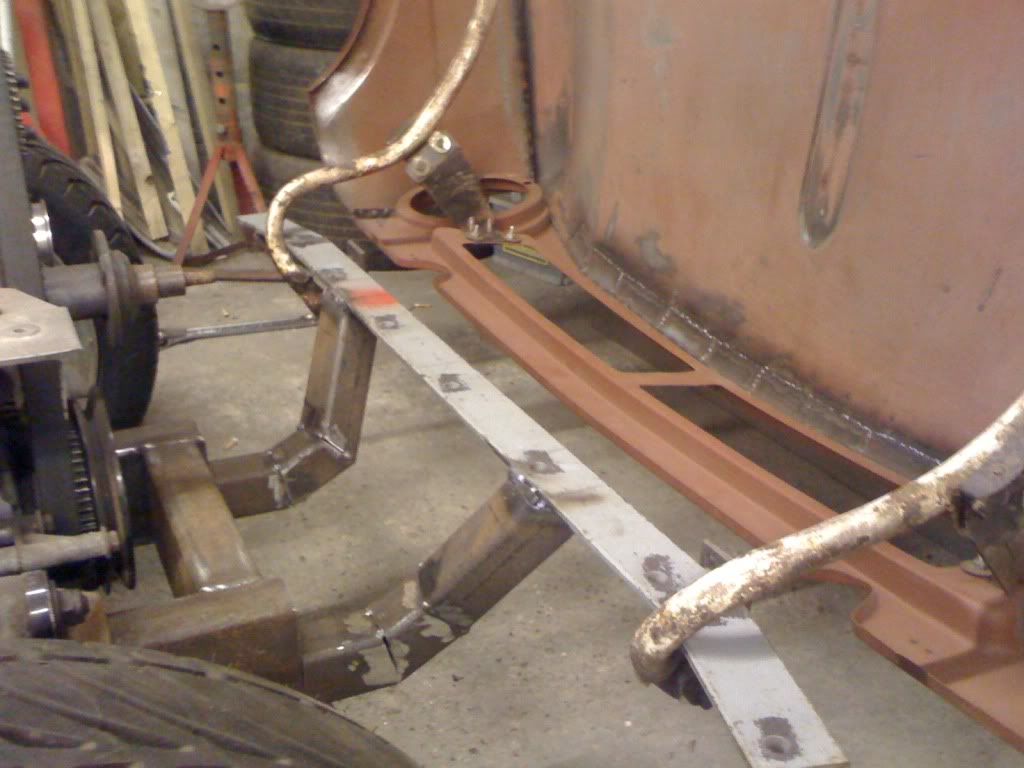 And now I’ve got an opening bonnet to go with my new opening doors! It’s not a perfect fit by any means yet and will need loads of adjustment, but it’s getting there. 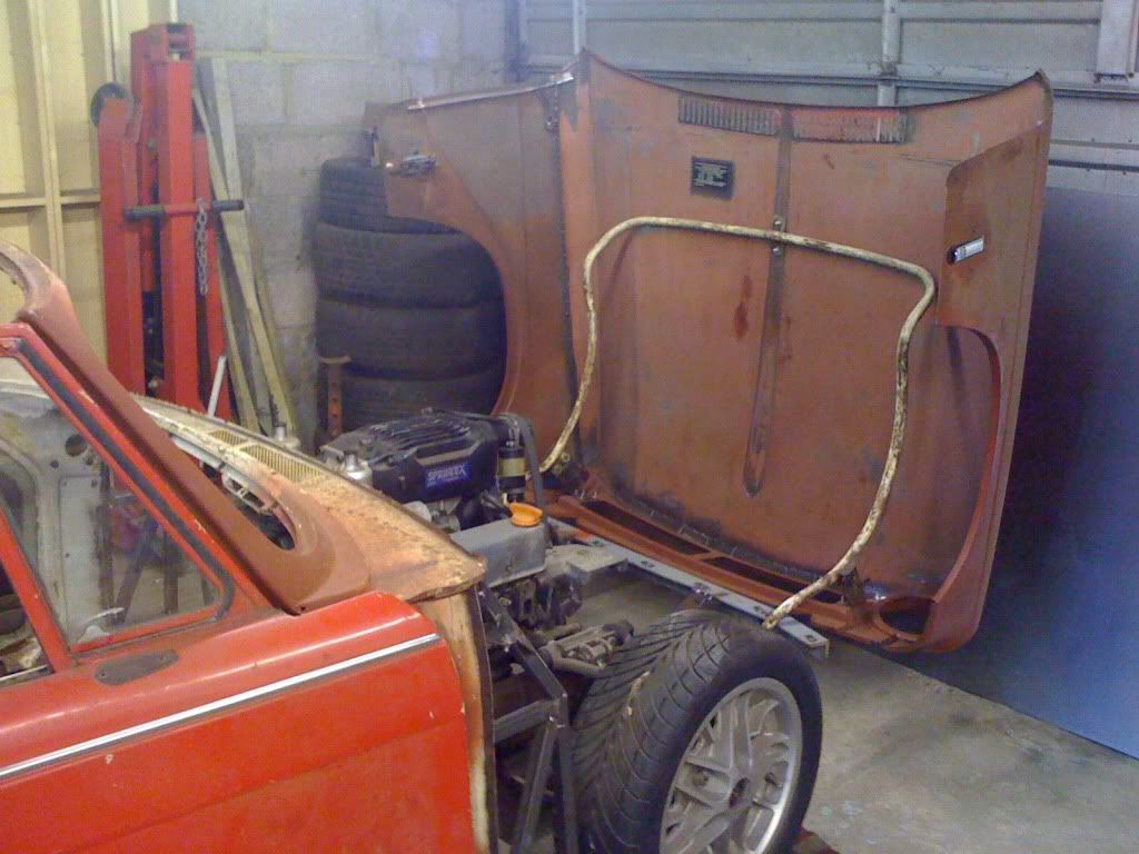 Opens rather further than standard, will have to add some check straps and stays at some point. 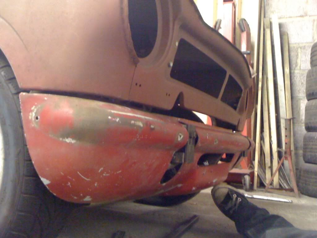 Here’s how the front valence goes on… 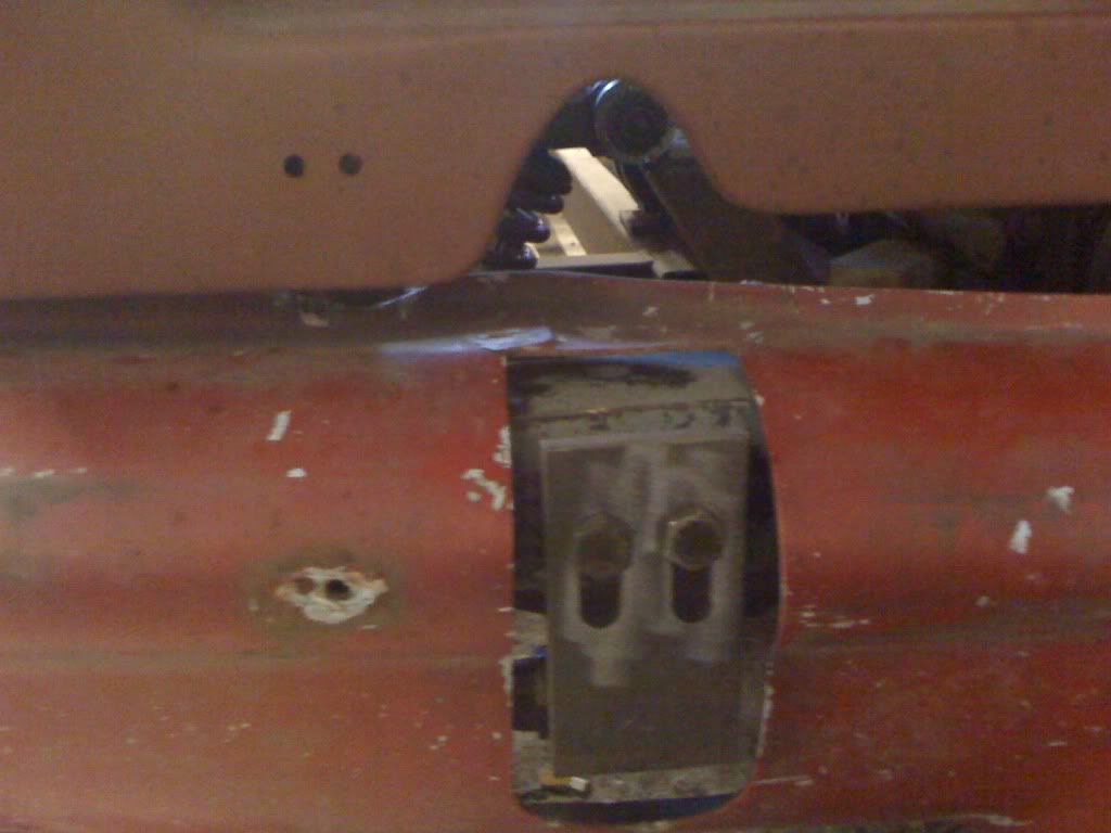 With the hinge poking through it. 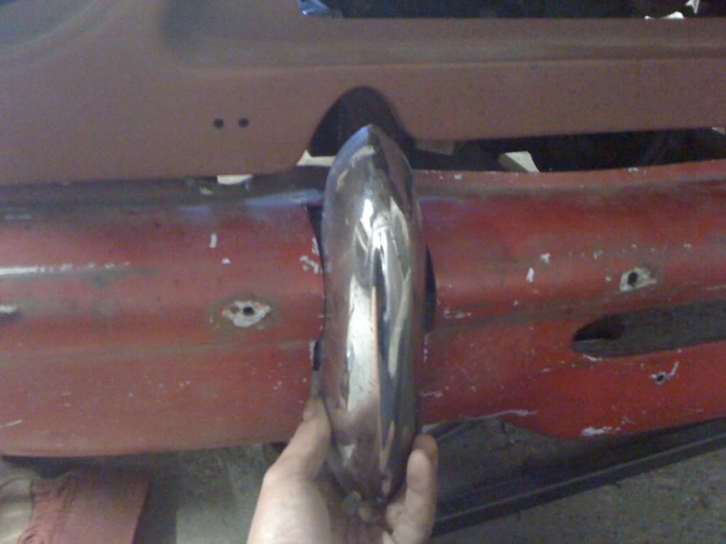 And just about enough room to get the over-riders on. Not sure if these are sitting a little further forward than standard, can’t remember how a proper Herald is meant to go together anymore…! 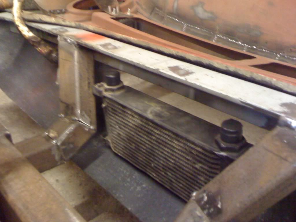 The oil cooler will sit hereabouts. A little higher up than this actually, otherwise it will be below the hole in the valence. 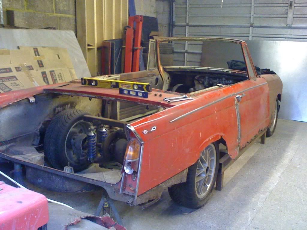 With the front end more or less together, thought it was about time to reunite the rear axle with the rest of the car. First step is to drag the rear half of the body into position. 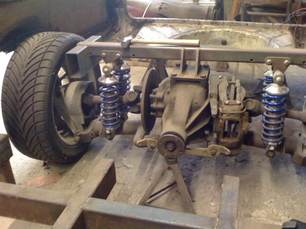 Next job is to work out how to attach the rear axle. Looks fairly straightforward in this shot, but I need to allow room for the brakes, the radius arms (which I’ve yet to make) and ideally, an exhaust. And all of this without intruding into the rear seat area. After a lot of sitting, looking, thinking and not an insubstantial amount of cigarettes I decided the way forward was to go around the outside. 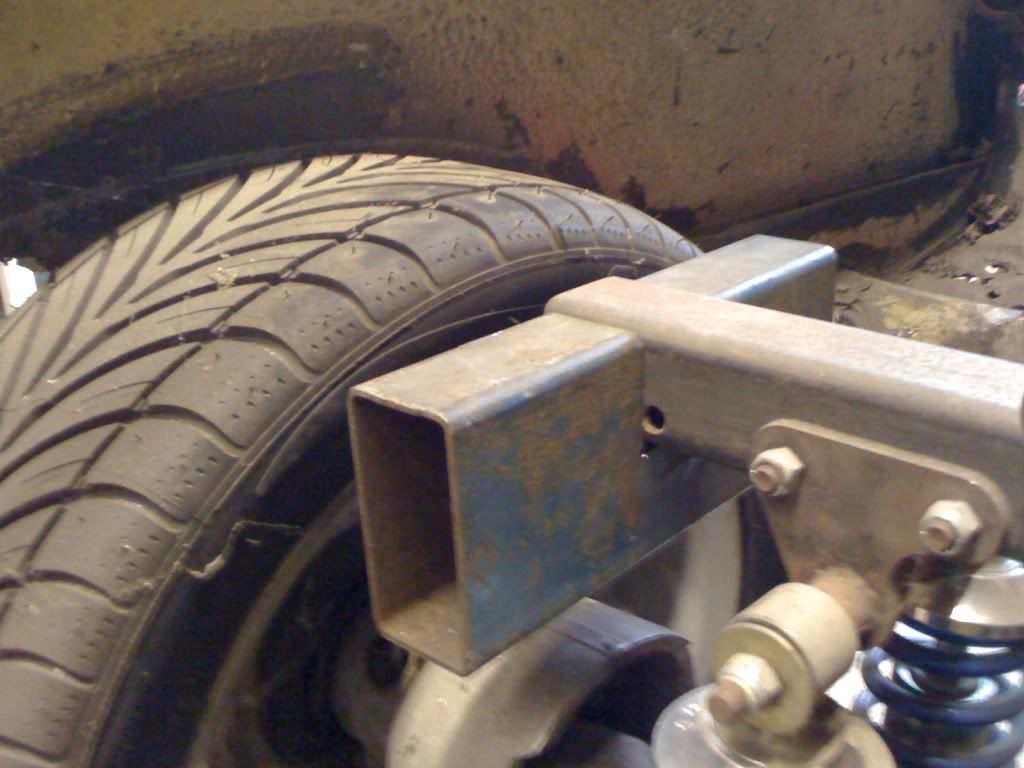 Here’s a ‘socketed’ bit of box section on the end of the diff crossmember. Going this route should make it easier to mount the inner wheel arches too. 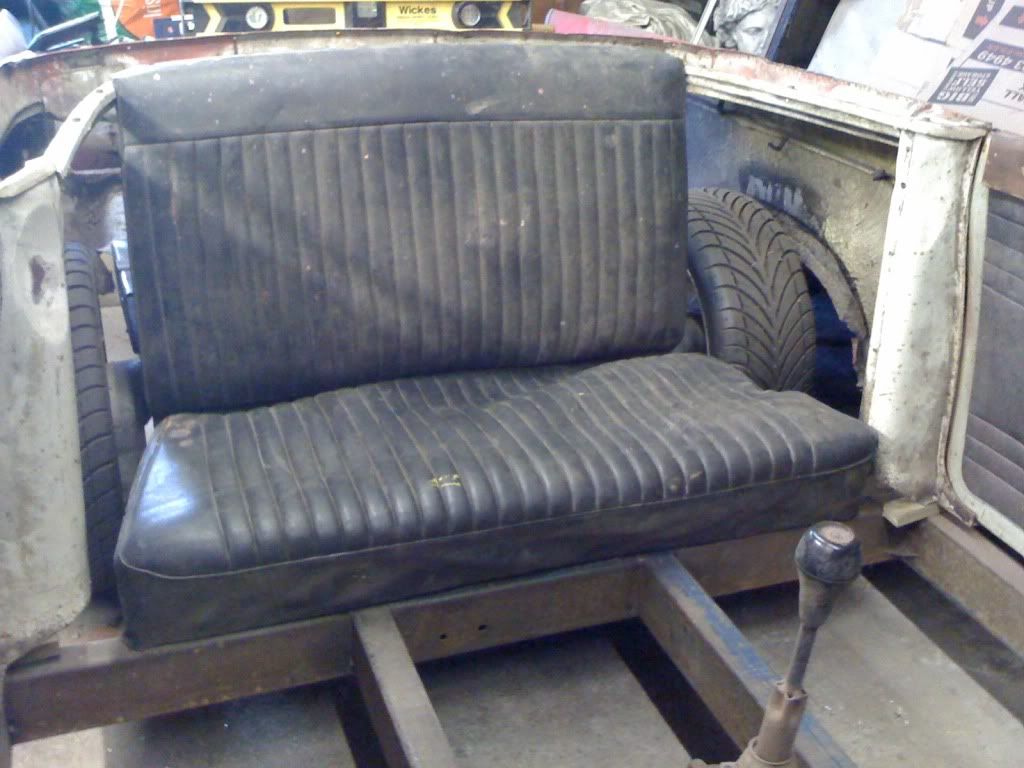 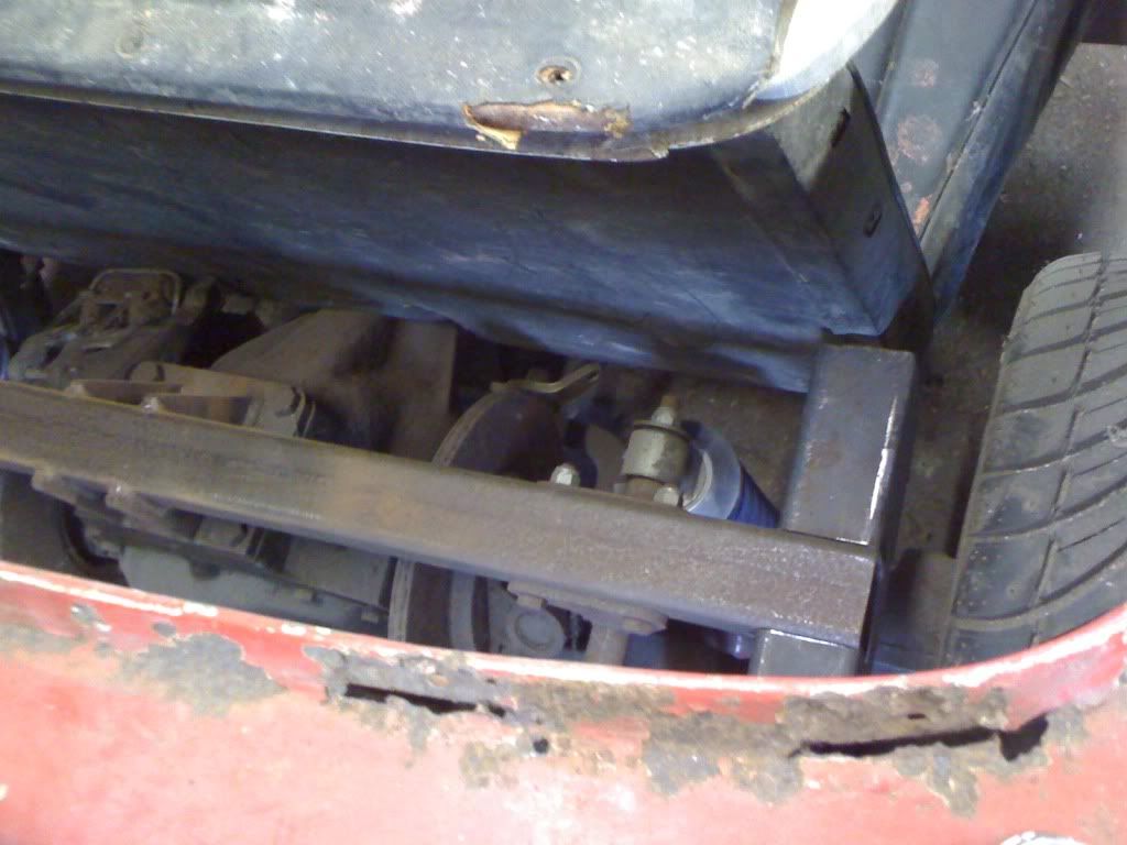 With the back seat dropped into place, you can see how little space there is for everything in here. The brakes are right up against the seat back as it is, and the nose of the diff is damn close to the base. It’s gonna be tight…! 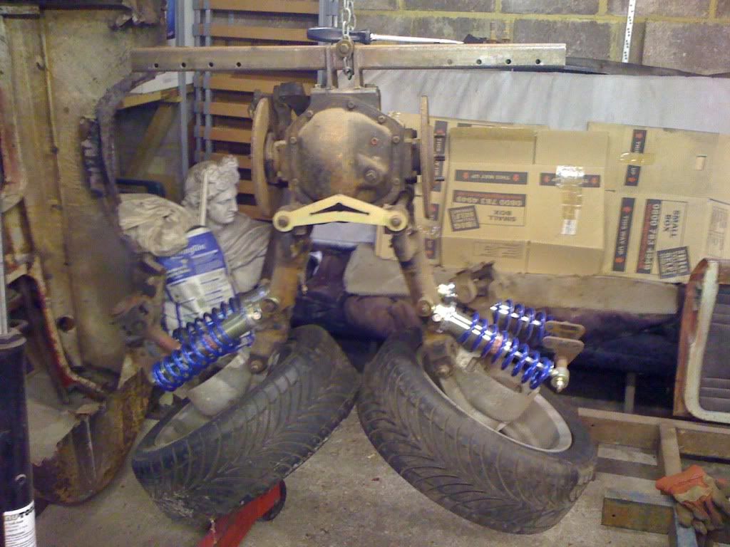 The brake calliper in the previous shot is just dropped into position, decided it would be a good idea to bolt it up properly to see exactly how much space I have to play with. This entails dropping the driveshaft and disc off. (Engine crane is handy for this!) 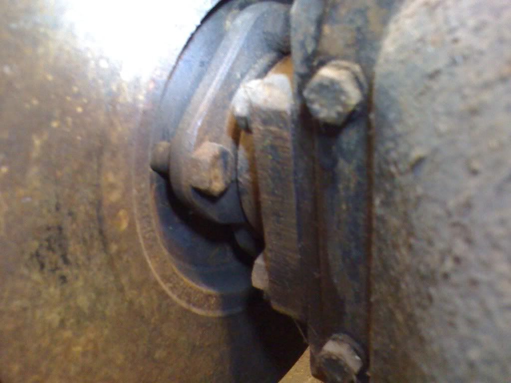 Annoyingly, I seem to have a mis-matched set of discs and callipers. With the calliper bolted up snug onto the diff, it’s holding the disk off the output flange by a good half inch… All of which is very tedious. 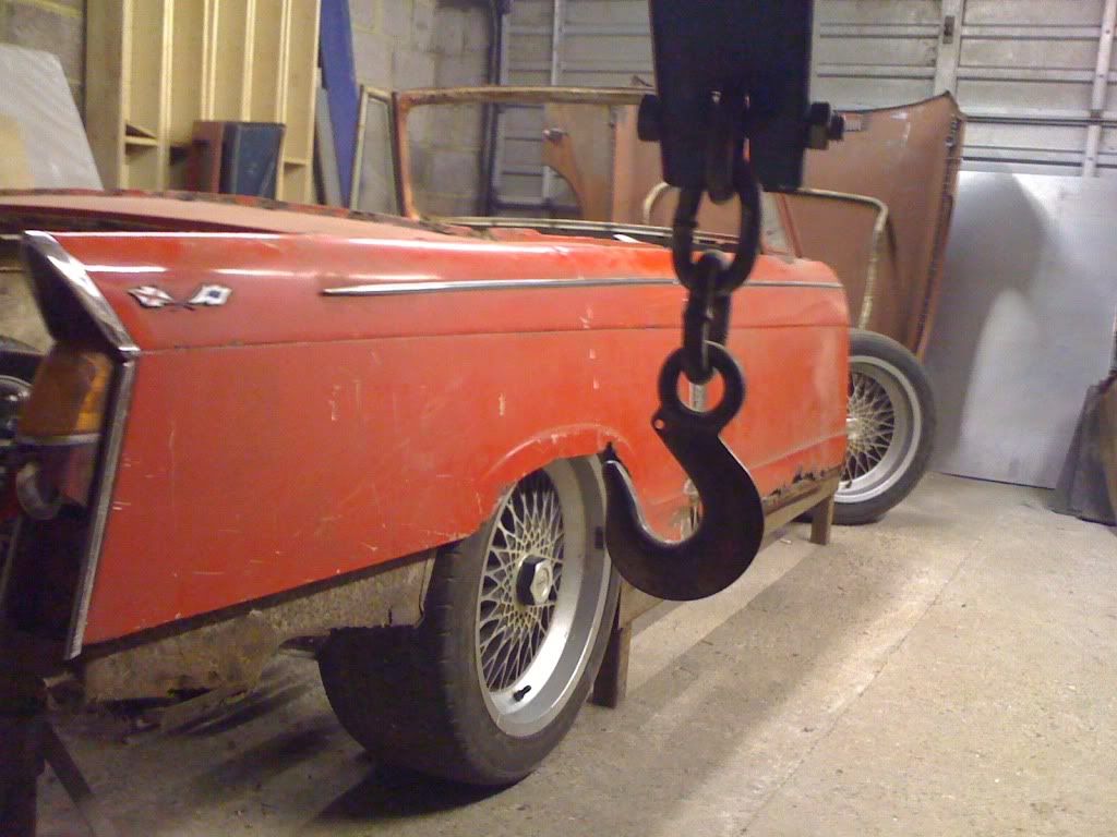 Feeling fed up with the disc/calliper issues, for a giggle I stuck a set of 17-inch alloys I’d had kicking around on to see how it looks. Silly. That’s how it looks. Very, very, silly. Cheers! Em. |
| |
|
|
sowen
Club Retro Rides Member
Posts: 2,245
Club RR Member Number: 24
|
|
Sept 2, 2010 20:41:58 GMT
|
Looking good there Maybe you might have a mismatch of dunlop and girling brake parts causing the clearance issues you have. The parts all look very similar but are not compatible  |
| |
|
|
Seth
South East
MorrisOxford TriumphMirald HillmanMinx BorgwardIsabellaCombi
Posts: 15,513
|
|
Sept 2, 2010 22:36:11 GMT
|
Fab looking progress  Nice to see it together and vaguely car shaped. |
| |

Follow your dreams or you might as well be a vegetable. |
|
megzy
Part of things
Posts: 364
|
|
|
|
|
epic keep up the good work
|
| |
|
|
|
|
Em
Part of things
Fuel Injected? Carb Infested!
Posts: 601
|
|
Sept 13, 2010 14:25:36 GMT
|
Cheers for the comments chaps! Sowen – yeah, that seems likely. Also seem to have ‘misplaced’ the other calliper… think there could be a trip to the scrappy in my immediate future… Seth – Cheers mate, probably going to be back in bits by the time you read thins though…! Megzy – Cheers fella! Not too much to show for this weekend, but having put the ‘sensible’ wheels back on the car and realised quite how little space there is to get everything in around the back end, thought I should work out some way of accurately positioning the rear axle and making sure it can’t move. 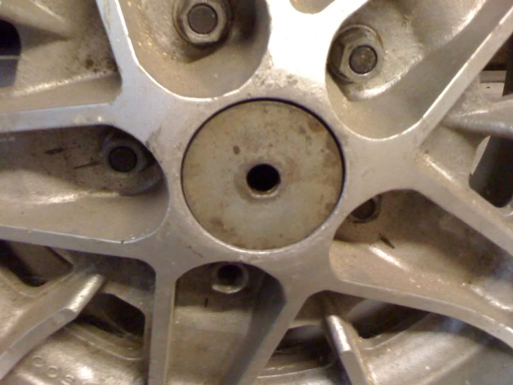 Had a rummage through my box of washers and in a rare stroke of good luck turned up four of these washers that are as near as damn it a perfect fit in the wheels. No idea what they came off but I’m glad I kept them now!  Bolted them to some bits of 2x4 timber with a little spacer behind…. 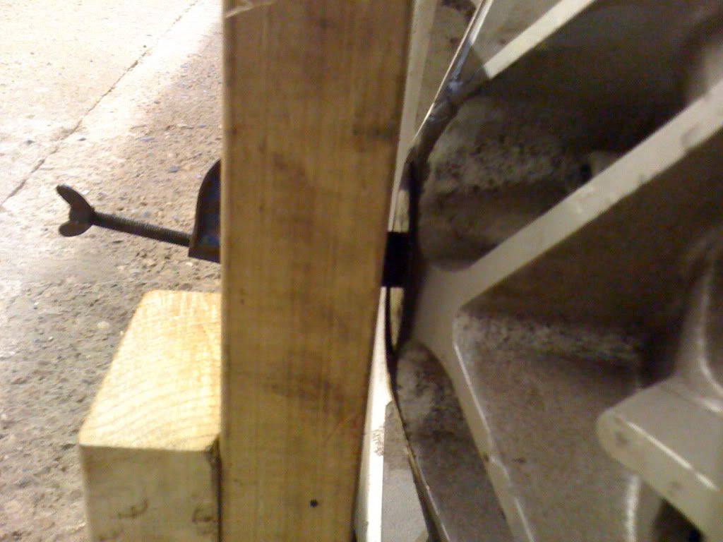 …so that they sit inside the wheel centres thuslike: 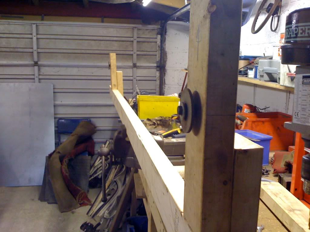 After a careful bit of measuring and a spot of schoolboy maths, I set the wheelbase at the standard 91 inches. Could have tweaked it slightly but the wheels look central in the arches and that’s what I’m looking for. 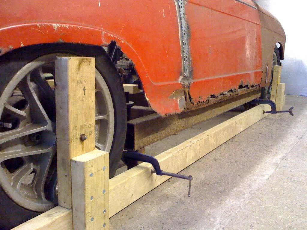 A happy side effect is that when the timber is clamped up to the little legs holding the chassis at ride height they also pull the front wheels into the straight ahead position (there’s no steering rack on yet…). Now I can attack the rear axle knowing it aint going anywhere… 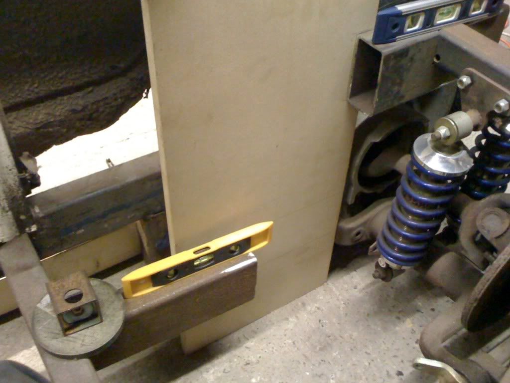 Used a bit of scrap wood to work out what needs to be connected to what. Looks like I’ve got heaps of room to play with here, doesn’t it?! 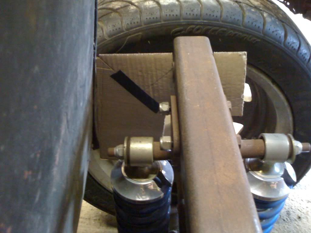 With the back seat in I’ve suddenly not a lot less space to play with, as a spot of Cardboard Aided Design flags up. 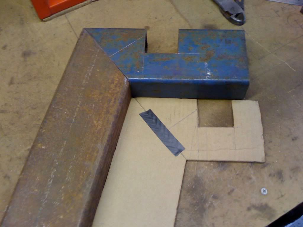 Cardboard template halfway to becoming metal…. 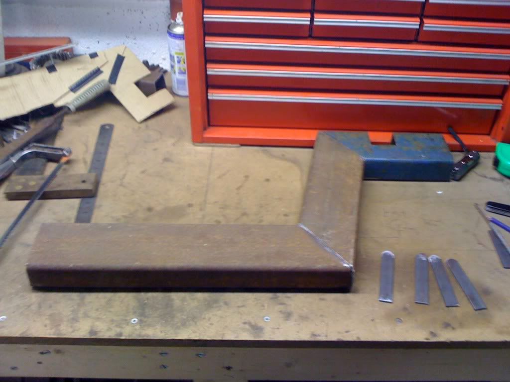 …and here’s the bottom half. Those four little strips of plate on the right… 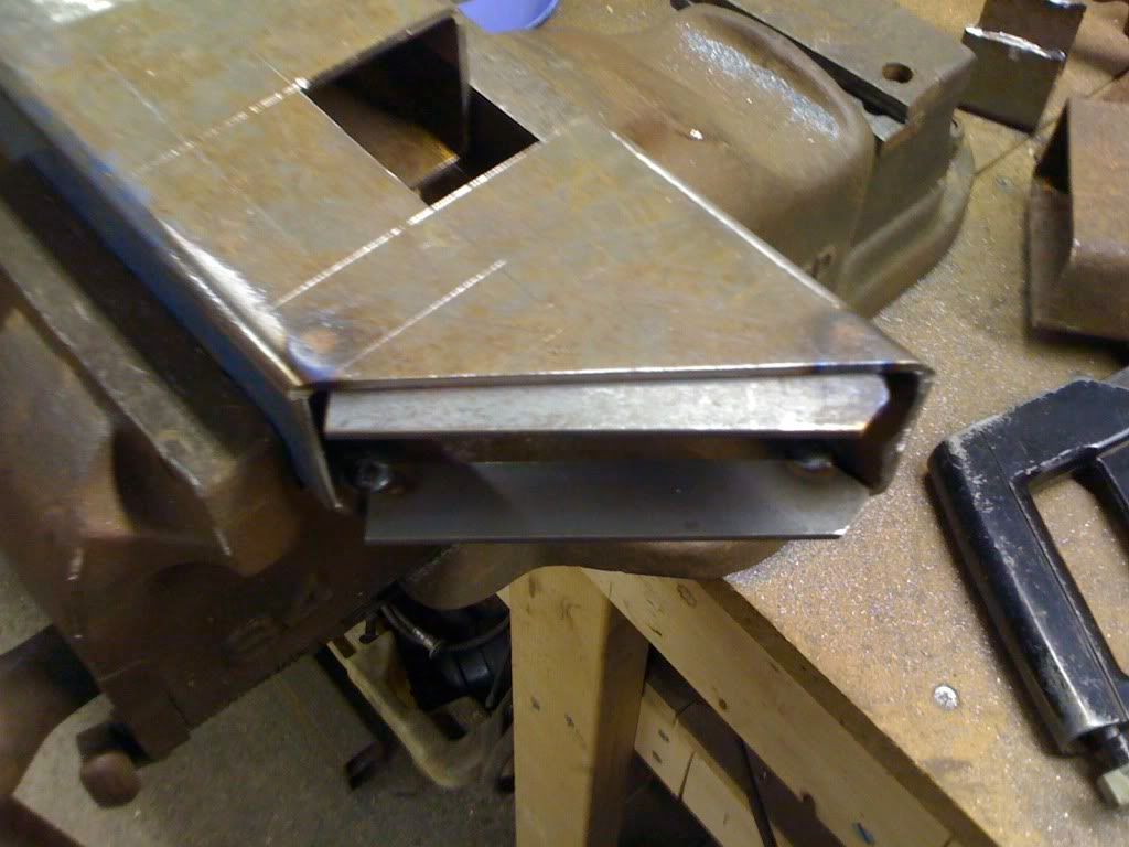 …get tack welded in here, both to help clip the parts together while mocking it up and to provide a little extra strength inside. Inevitably, there are slight gaps due to cutting and measuring inaccuracies, theses should allow me to weld through and get some nice solid joints. More on that next time…. Cheers, Em. |
| |
|
|
Colonelk
Posted a lot
Posts: 3,740
Club RR Member Number: 83
|
|
Sept 13, 2010 18:18:03 GMT
|
|
This is amazing! keep it up!
|
| |
|
|
Em
Part of things
Fuel Injected? Carb Infested!
Posts: 601
|
|
Sept 22, 2010 14:20:49 GMT
|
Cheers Colonel! Will do! Right, where was I? Oh yeah, making rear kick-ups... 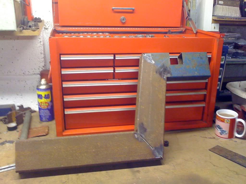 With all the sections cut (badly!) to size (really wish I had a chop saw…) I tacked one up. Once I was happy it was right, ground down the tack welds on one face… 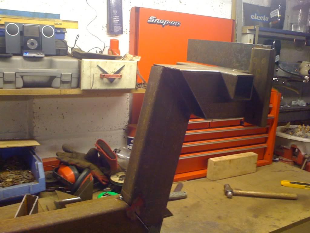 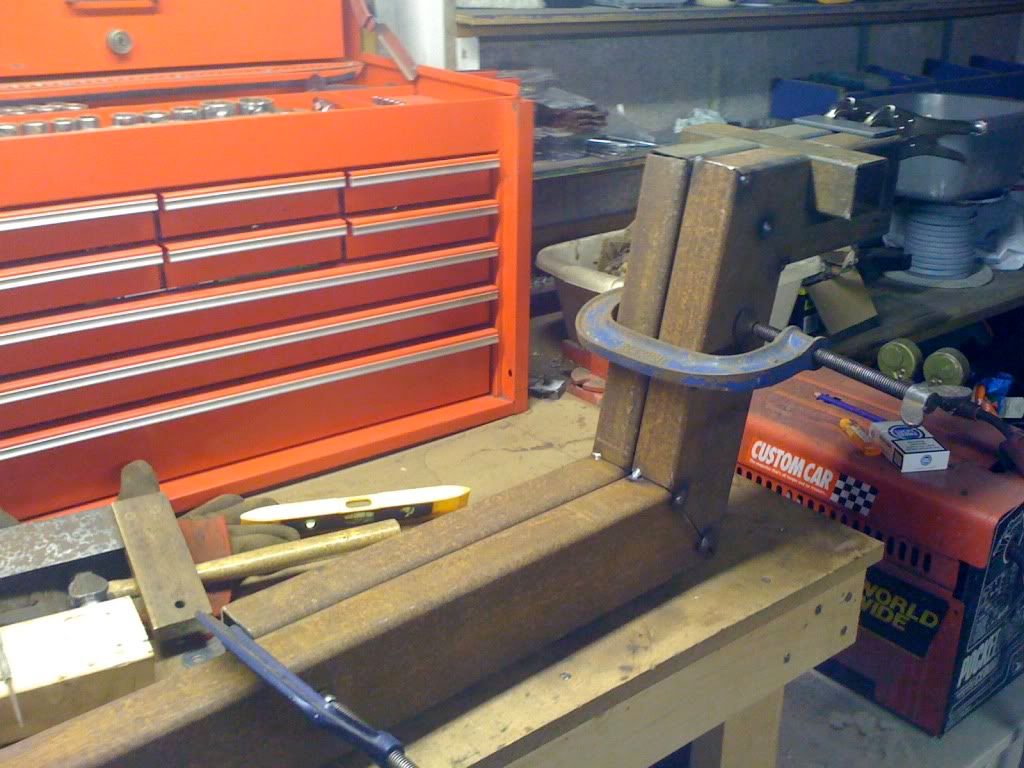 …so that I could clamp the sections destined for the other side to it and, in theory, end up with two identical bits of chassis. 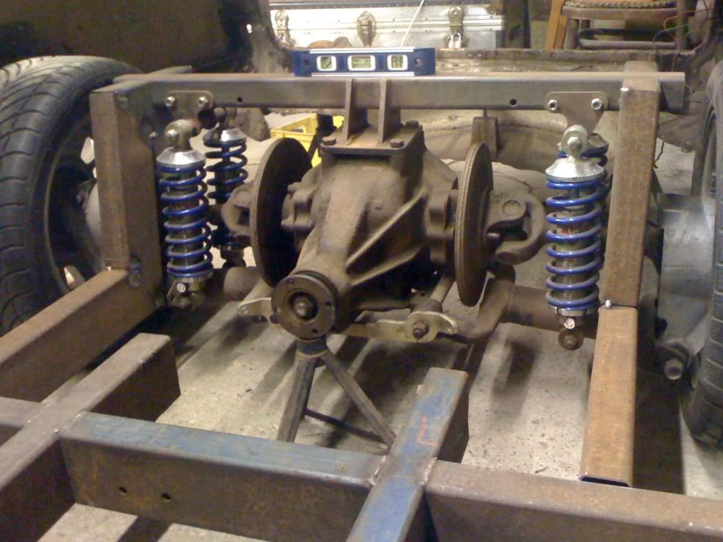 Remarkabley, it worked! Here’s the pair of kick-ups roughly in position from the front… 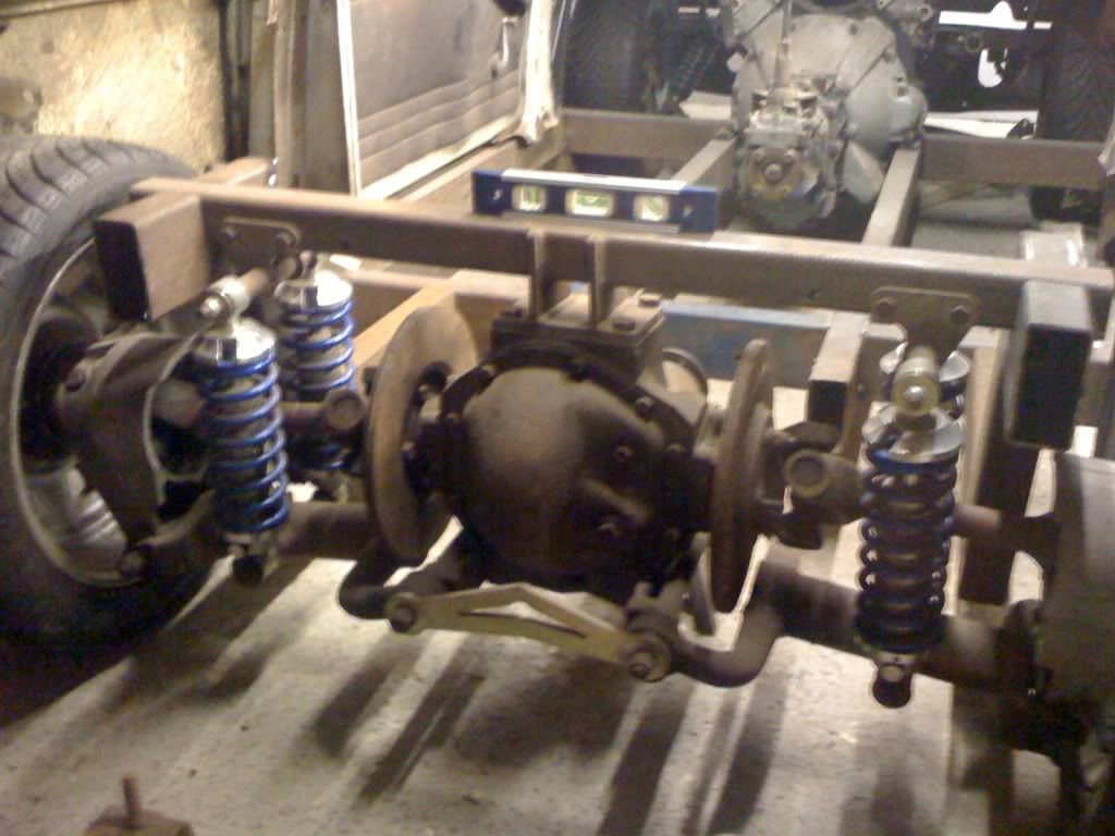 …and from the rear. Lovely. The next exciting problem I have is how to accommodate the radius arms, which to complicate matters further, I don't actually have yet. The radius arms attach at the outer end of the lower-wishbones and need to run forward to meet the chassis somewhere along the same axis as the lower-wishbone inner pivots, triangulating the lower suspension arrangement and preventing the stresses of acceleration and braking from putting too much strain on the inner pivot bearings. 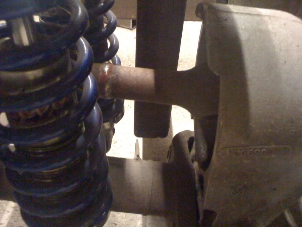 Problem is, some clot has just plonked a dirty great chassis section in the way. Here’s where the radius arms are going to not fit…. 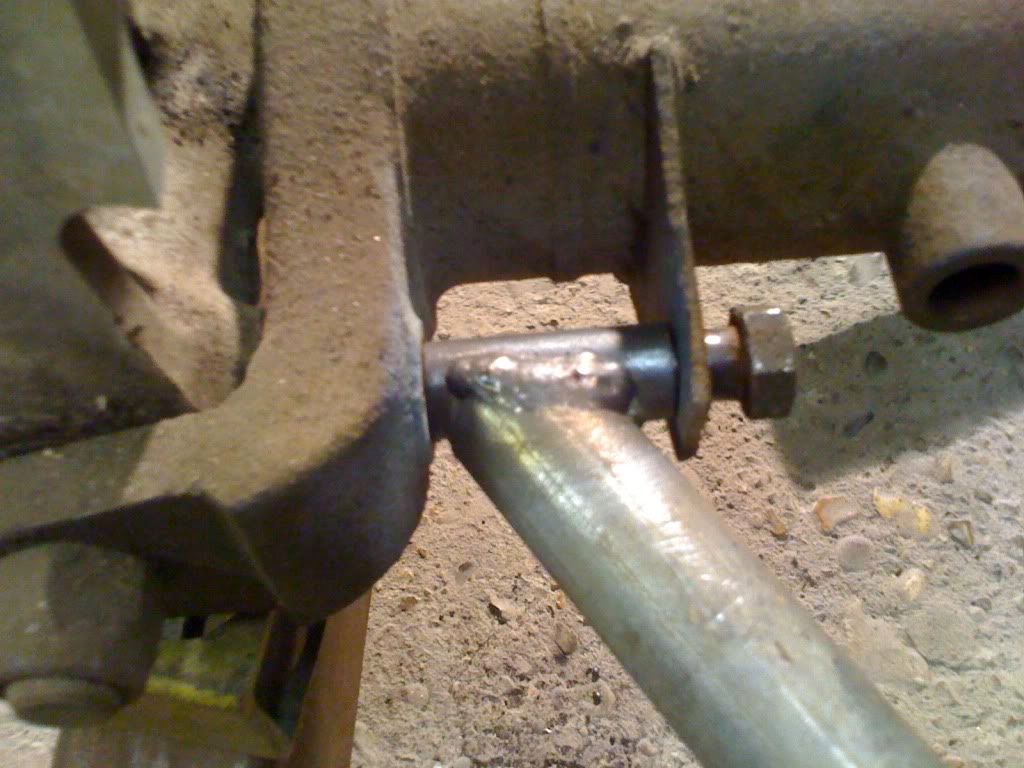 Clearly, some clearancing will be needed. To work out how much, I mocked up a radius arm with a bit of collar, a bit of old tube (actually by broom handle!)… 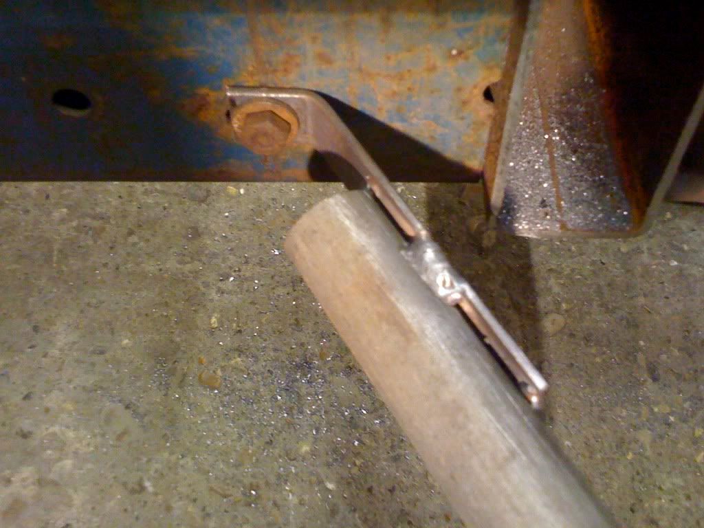 …and a bit of bar that attaches with a bolt through a hole along the lower wishbone inner pivot axis. 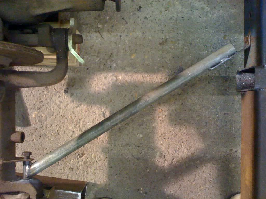 With the wheels, springs and shocks off the diff chocked up at ride height and an offending bit of chassis lopped off, it all moves up and down smoothly. 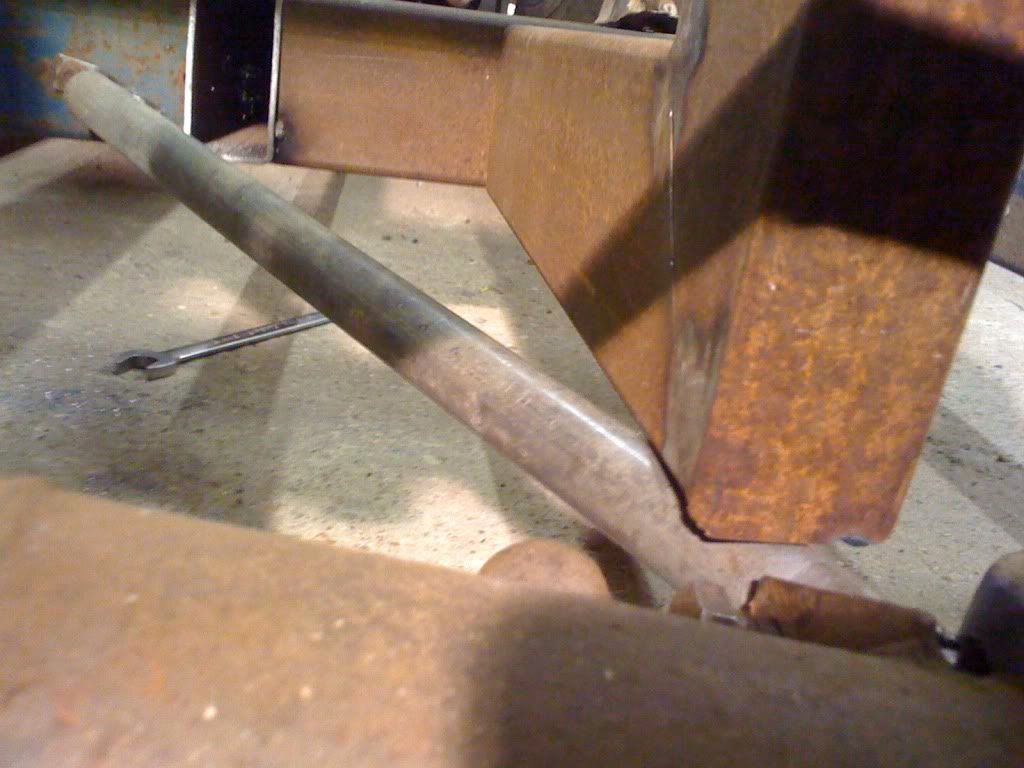 Now I can work out how much space needs to be created to allow some room for manoeuvre .... (If you’re wondering why I didn't take this into account when I made the kick-ups, the answer is it was hard enough to get the kick-ups right on their own, I’m not clever enough to make them out of more than three sections…!) Join me next time as I chop up the new sections of chassis I’ve just spend days making! Cheers, Em. |
| |
|
|
|
|
|
Oct 14, 2010 18:10:17 GMT
|
looks brill though a lot of work, am glad mine only needs a few things doing |
| |
|
|
|
|
|
Oct 14, 2010 19:39:43 GMT
|
Strombergs? Theres no searing allowed on this site mate!! I was thinking of these.. 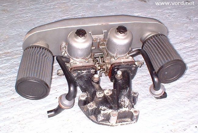 They look shorter than yours - might get you and extra inch. Ooo errr! Its looking awesome, and even more awesome with the 17"s, it looks like a cartoon!  |
| |
Koos
|
|
luckygti
Posted a lot
I need to try harder!
Posts: 4,912
|
|
Oct 14, 2010 22:26:00 GMT
|
Epic Haven't looked at this for a while, but it's starting to come together! This car is going to be seriously cool! Those rims look spot on as well |
| |
|
|
340R
Part of things
Posts: 138
|
|
|
|
|
Epic build and fab skills here. Top work.
Adam
|
| |
1988 Volvo 340R 2.0 16v
1988 Volvo 350R in progress!!!
|
|
Em
Part of things
Fuel Injected? Carb Infested!
Posts: 601
|
|
|
|
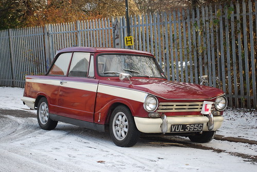
Thanks for all the comments chaps! evg1990 – Lovely little saloon you’ve got there, looks like a great buy! mdh - Sorry about the bad language! (I actually really like Stroms!) That’s an MGBV8 set up, I believe? I did consider a set of those ages ago, think they would have interfered with the heater though. This was during the project’s first incarnation, with standard chassis and bulkhead in place… And how come the MGs got cool stuff like these: 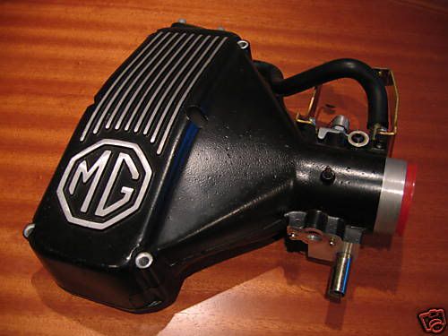 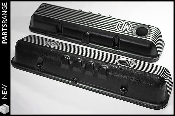 …while the V8 Triumphs didn’t….?! luckygti – Yeah, getting there slowly! Big rims don't fit actually, bit of a shame really… 340R – Thank you Sir! So where was I?! Ah yes, about to chop up my new chassis sections. 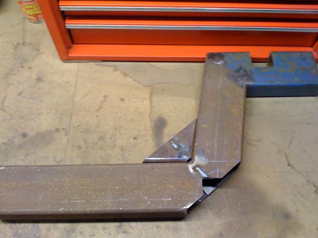 After a bit of trial fitting with the ‘mock up’ radius arms, I reckoned a good starting point would be to lop off the corner which can then be cunningly welded back in above, to restore some of the strength. This gave me a good starting point, but there’s still clearance problems (which I forgot to photograph). Decided that to do this right, I needed the real-deal radius arms.  So sent these dimensions off to ”Pop Browns”…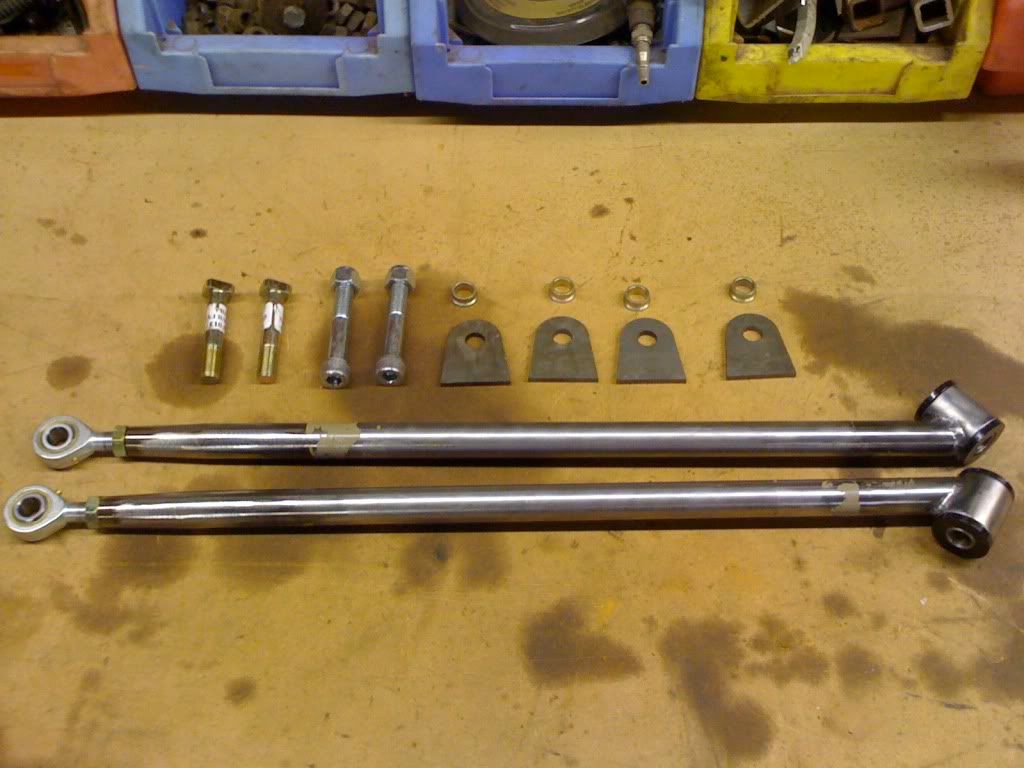 And a little while later these turned up! Beautiful pieces of work, as ever. 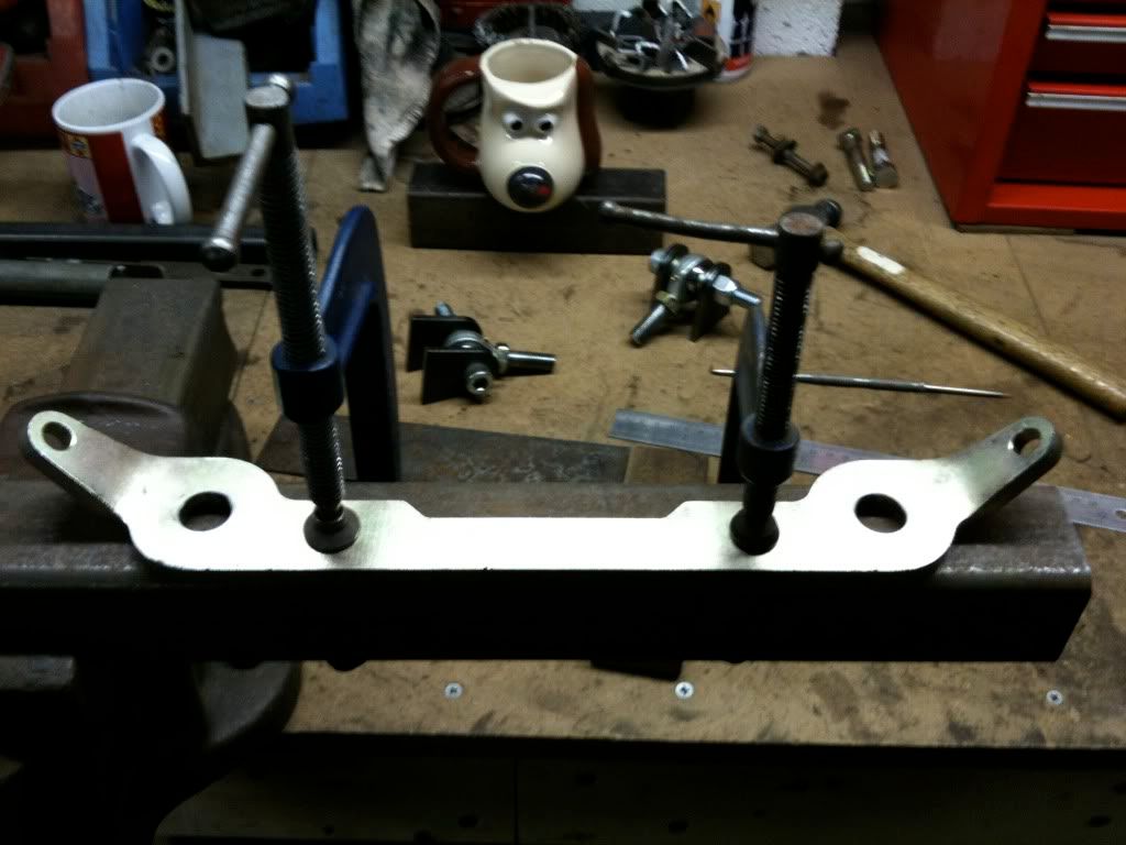 Next issue is working out how to mount them accurately on the same axis as the fulcrum shafts. Reckoned a good place to start would be to mark the centres on a bit of box section, using a tie strap as a template. 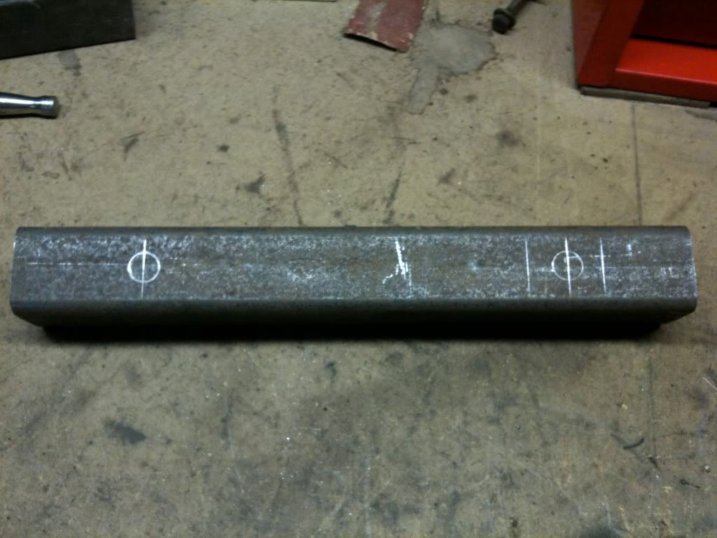 Thuslike. 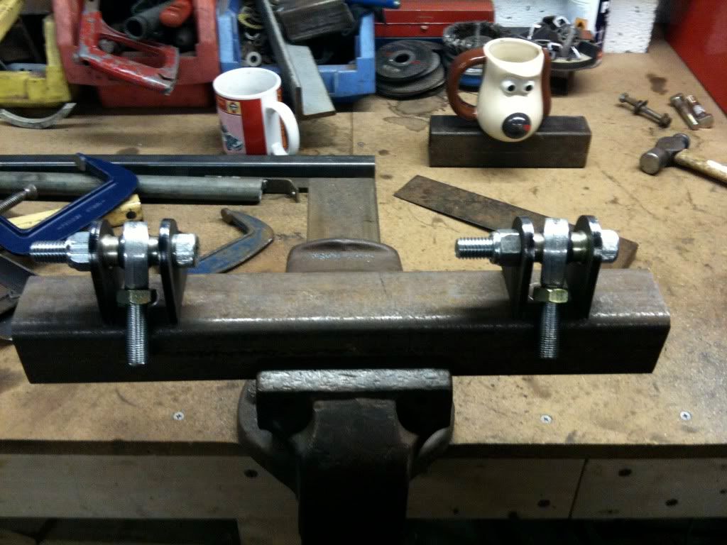 Then as long as the centres of the rod ends are on the line, I should be alright, at least left to right. Up and down I’ll worry about later. 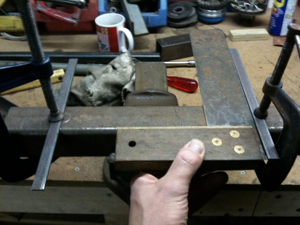 To project the centre lines forward, I clamped on a couple of pieces of bar, the centre line is the inside edges. 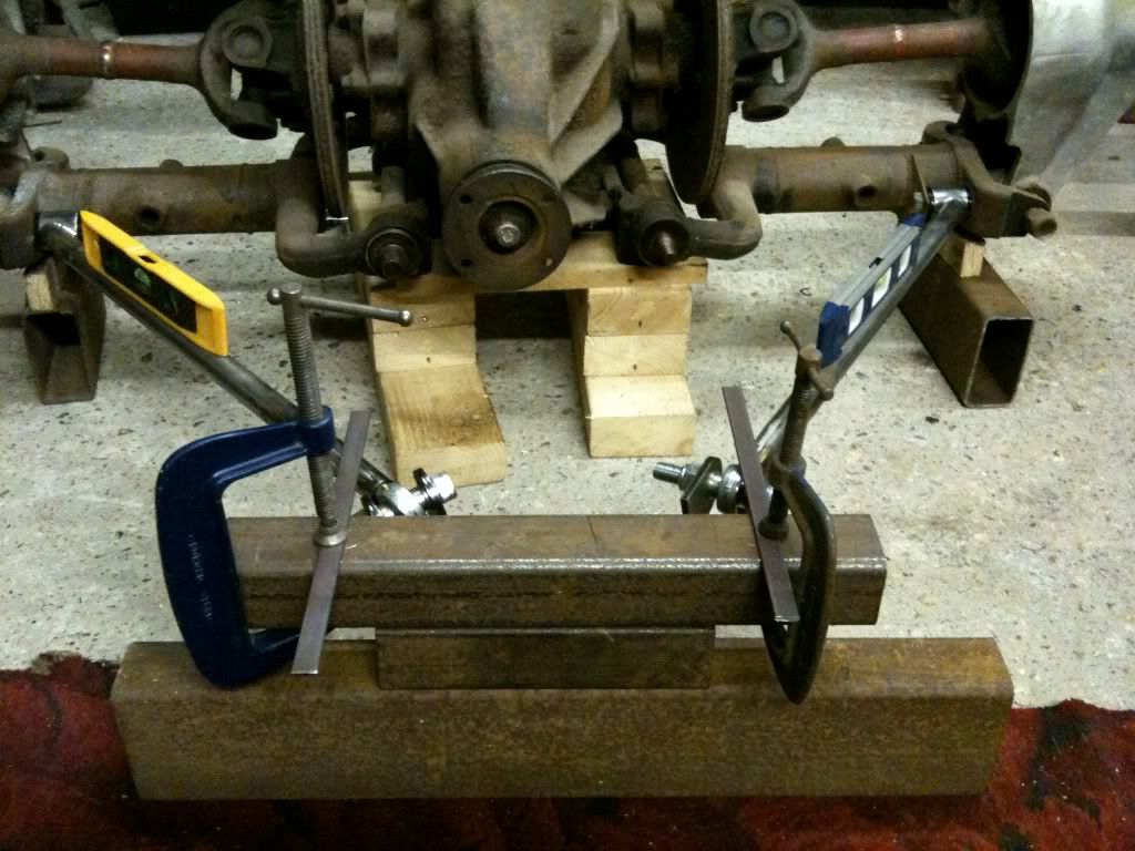 With the arms back on the axle and everything set up level-ish, I offered up my little jig-type-thing. 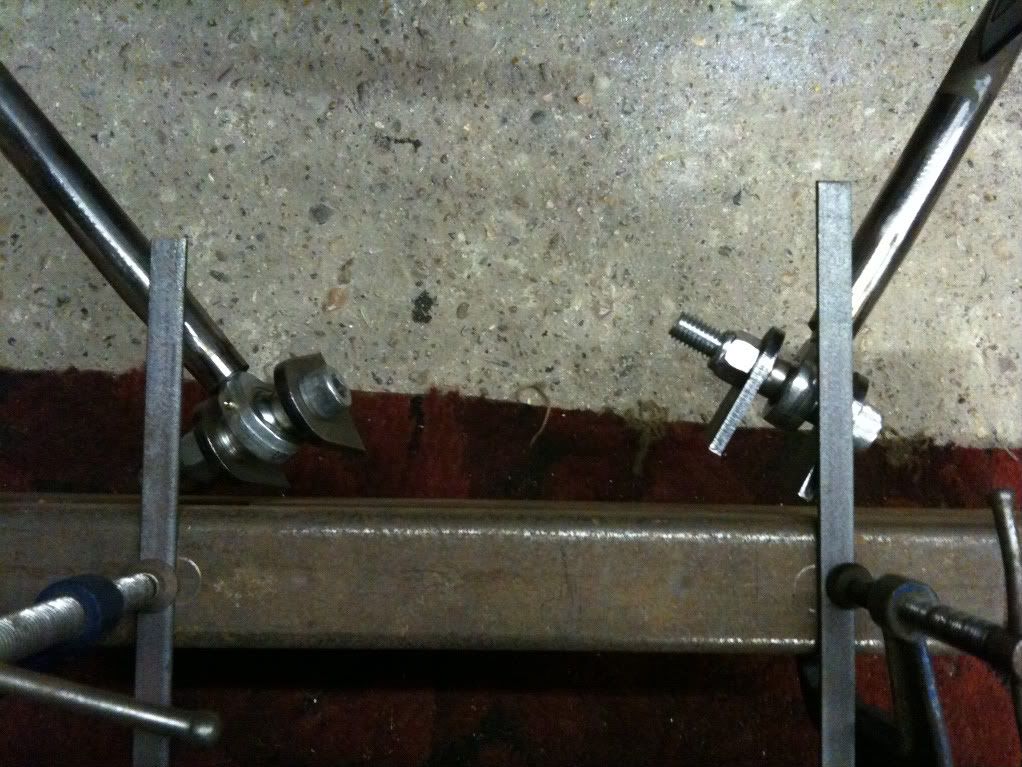 Disaster! Some “measuring inaccuracies’ on my part meant that the rod ends were too close together. The one on the right is on the centre line, lefty needs to move along a bit. 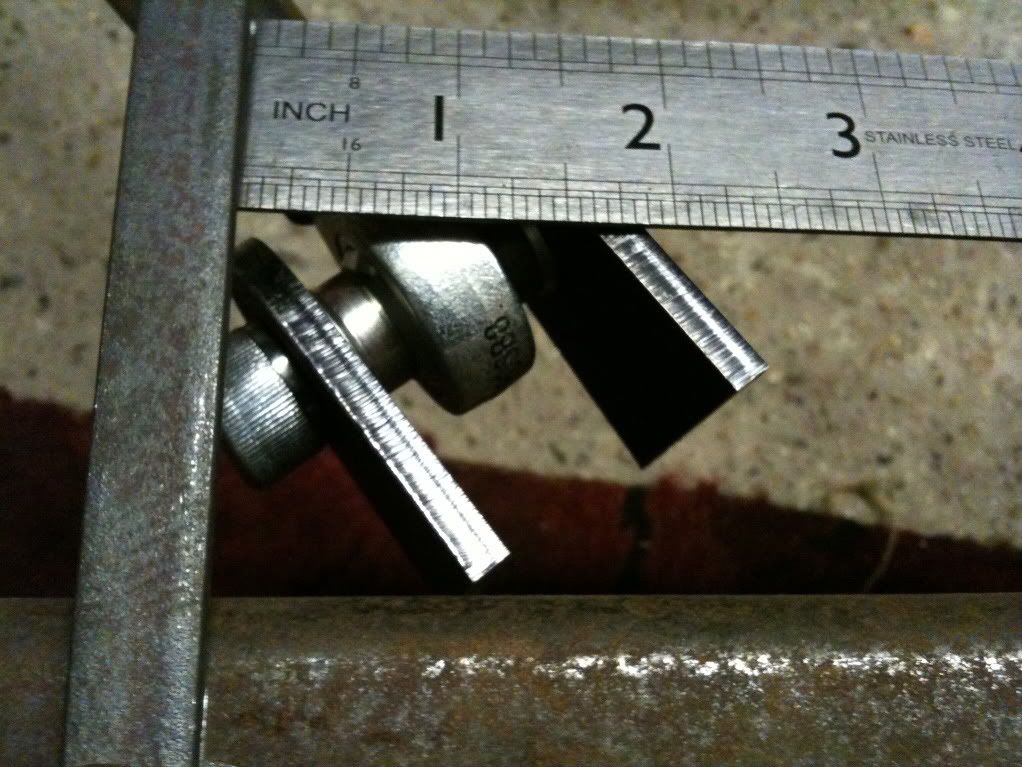 About an inch to the left, to be imprecise. 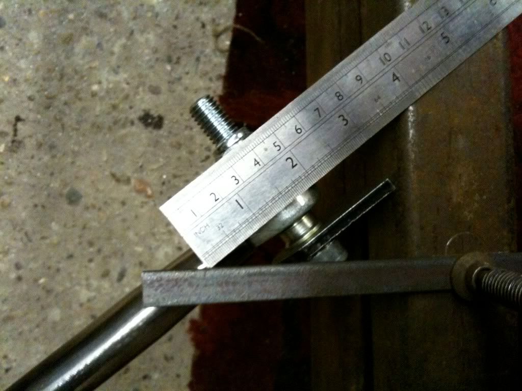 With a little schoolboy maths, I reasoned that seeing as the distance along the arm from the centre of the rod end to the centre line is 1 and a half inches, allowing for two locknuts both a quarter of an inch thick, if I took off an inch from each arm, I’d be spot on. In theory…. 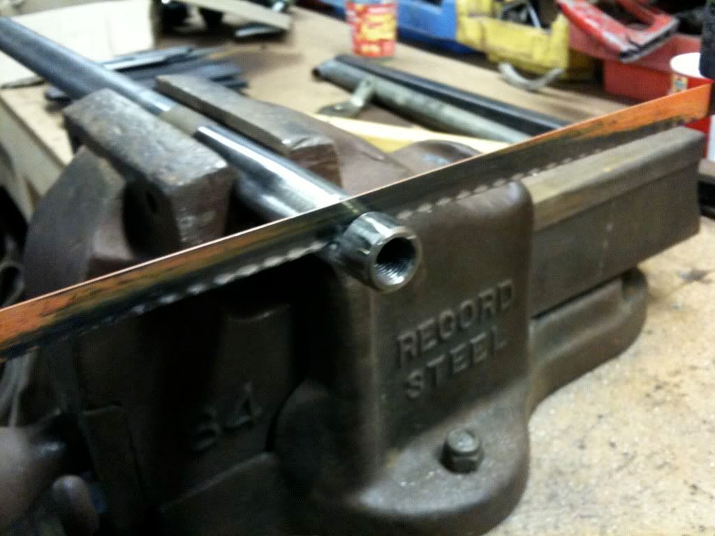 Thing is maths ain’t by strong point, so I erred on the side of caution and took of half an inch to start with. 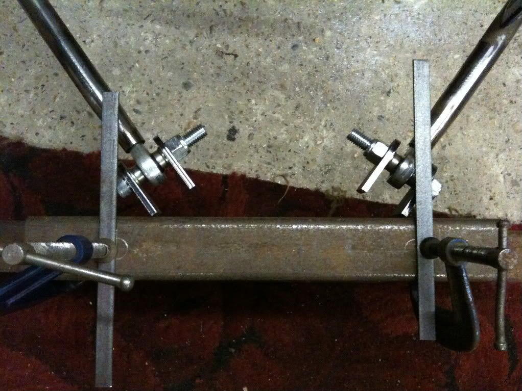 This brought them close, but no cigar. 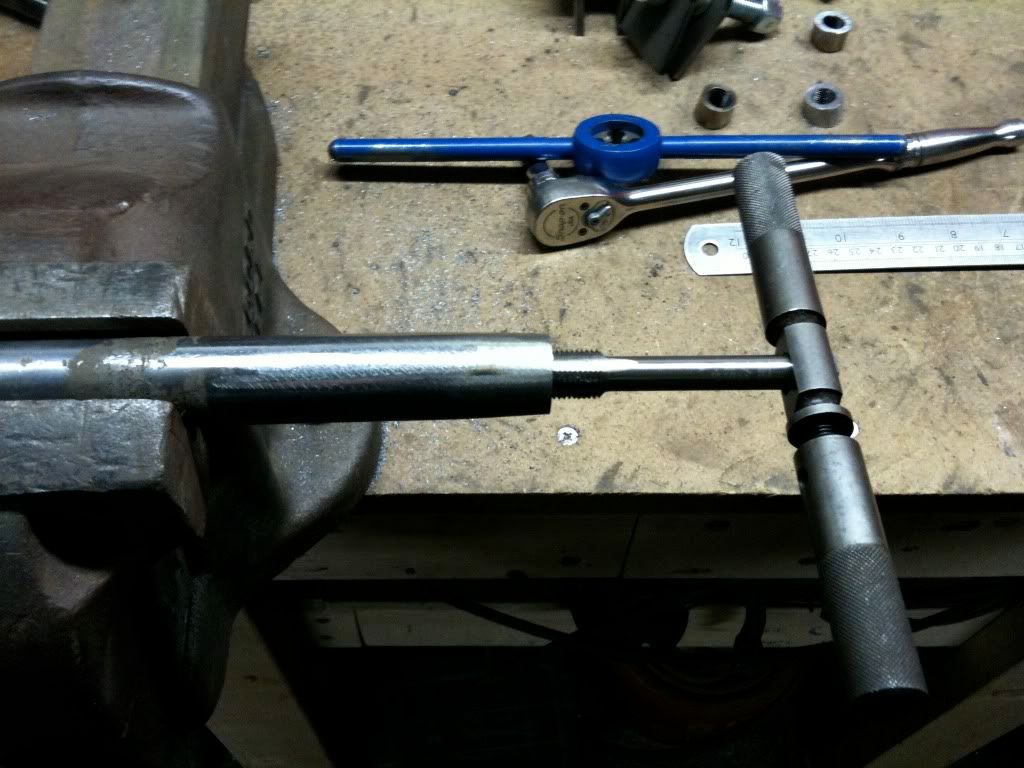 So off with another half an inch. Had to run a tap down to the bottom to get a little more usable thread, and also lose a tad off the bottom of the rod end. 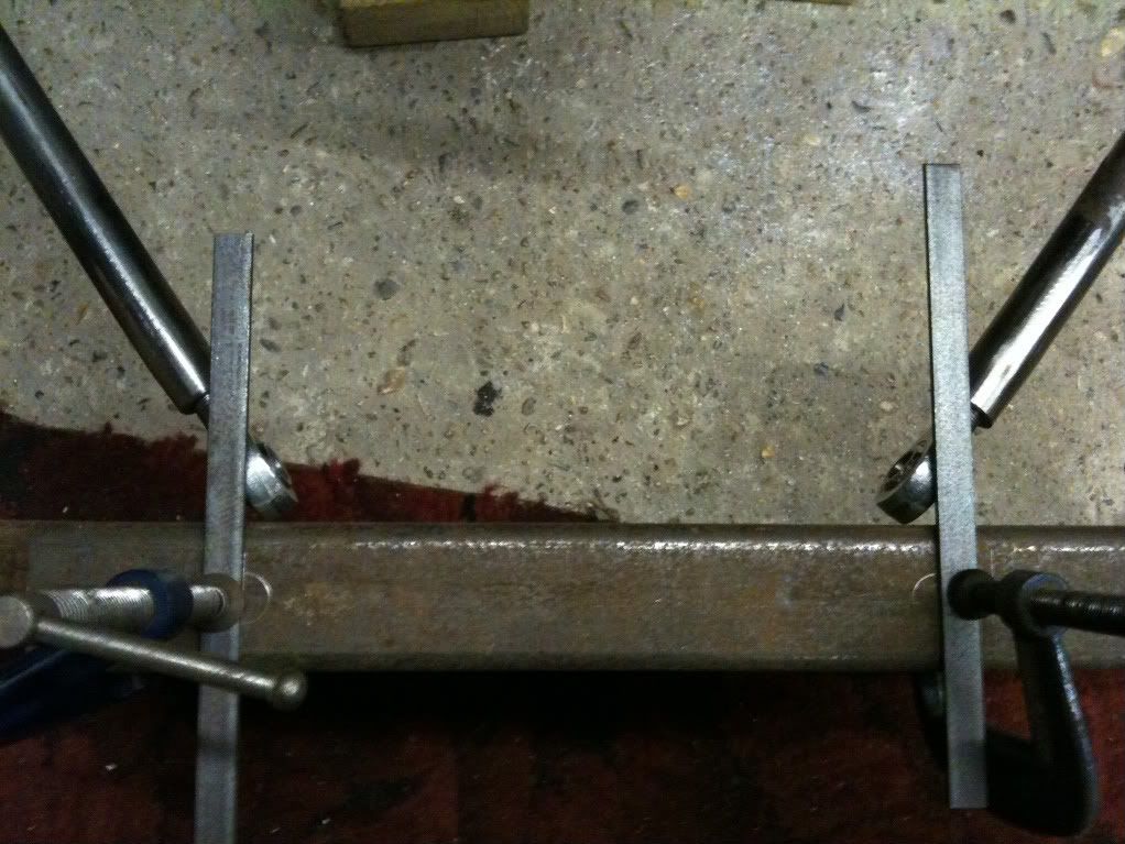 And Viola! We’re there. Looks a little off, but that’s parallax, promise! Plan is now to weld the brackets that came with the arms to the section of box section, which will then get welded to the cross member. A rather involved process, but hopefully it'll result in accurate placement and no binding. We’ll see….. Cheers! Em. |
| |
|
|
Seth
South East
MorrisOxford TriumphMirald HillmanMinx BorgwardIsabellaCombi
Posts: 15,513
|
|
|
|
I love watching a carefully considered and planned project slowly come together. |
| |
Follow your dreams or you might as well be a vegetable.
|
|
Em
Part of things
Fuel Injected? Carb Infested!
Posts: 601
|
|
|
|
|
Heh heh, I'm not sure it's either carefully considered or planned, but it's certainly slow!
|
| |
|
|
|
|


 Nice to see it together and vaguely car shaped.