|
|
|
|
|
I've been given a side-project by one of the technicians at uni, to get their Ricardo E6 Variable compression engine running. Not taken any pics of the item itself yet, but I've got a few of the instruction manual (proper retro typewriter written jobbie!) and a couple of pics of similar models from google. No doubt, a few people on here might find it interesting, so any progress I make on it will be thrown up on here ;D Basically, it's a single-cylinder 507cc engine, and when setup for running spark-ignition (petrol/lpg/etc) you can vary the CR WHILST RUNNING to anywhere between 4.5:1, and 20:1! There's a very very large electric motor, used as the starter, and also to measure output. Whilst moving it from the old workshop, to the new workshop a couple of years ago, the people removing it, simply took a ruddy hacksaw to the cables running from the motor, and now they've got no idea how to wire it up again! So my task, is to either get that motor working again (not chuffing likely!) or find a way to mount it to their existing hub-dyno. Will more than likely update it to ECU controlled fuel injection and ignition, rather than the mechanical injection, and magneto ignition. pics of similar units: 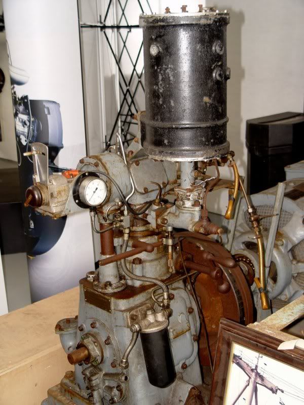 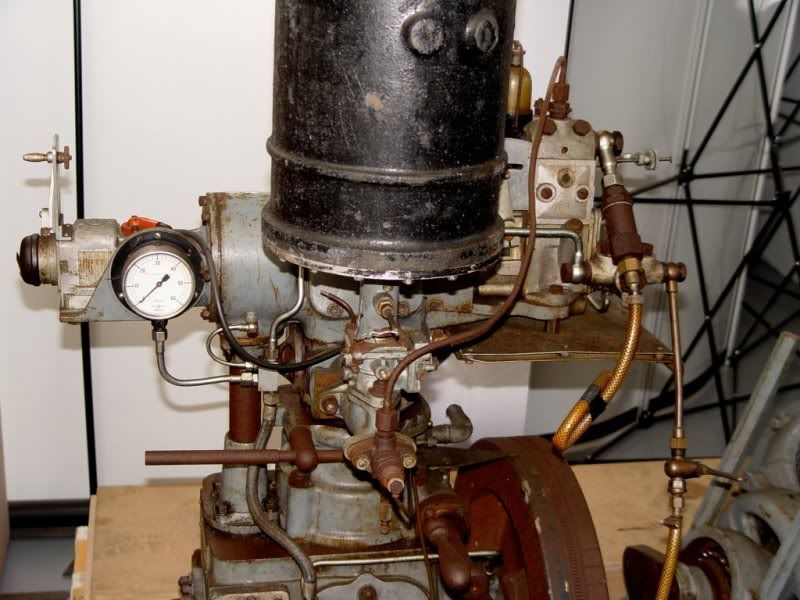 The black cannister is the air filter, underneath that is the Zenith carb, and under that is the mechanical injector (horizontally) The big rusty-looking arm to the left of the injector, "locks" the CR, whilst the control down and to the right, moves the cylinder head+cylinder bore, up or down. 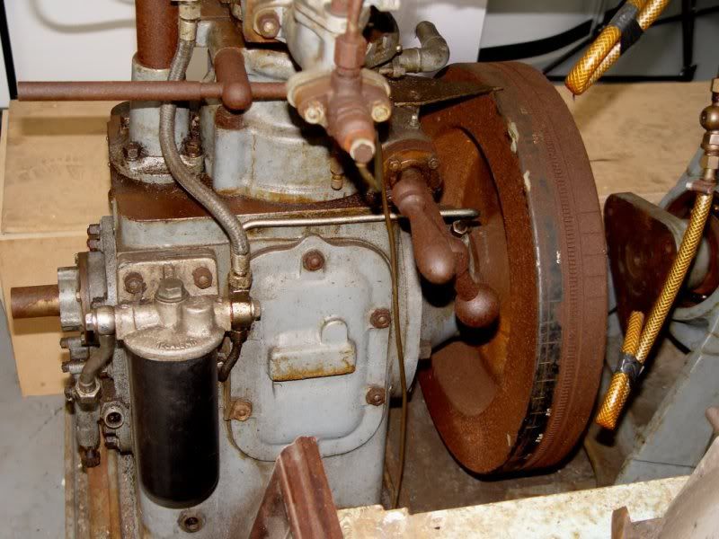 CR varying control a bit more obvious in this pic - along with the sheer size of the flywheel bulk! 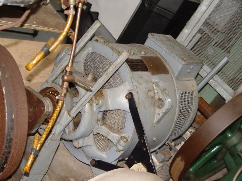 This is the motor, after manually adjusting the field voltage, and armature voltage, you can adjust the amount of force being transmitted via the torque-arm (the black bit poking off the side) to a spring... which apparently means you can figure out the power being made. To me, this seems ridiculously over complicated 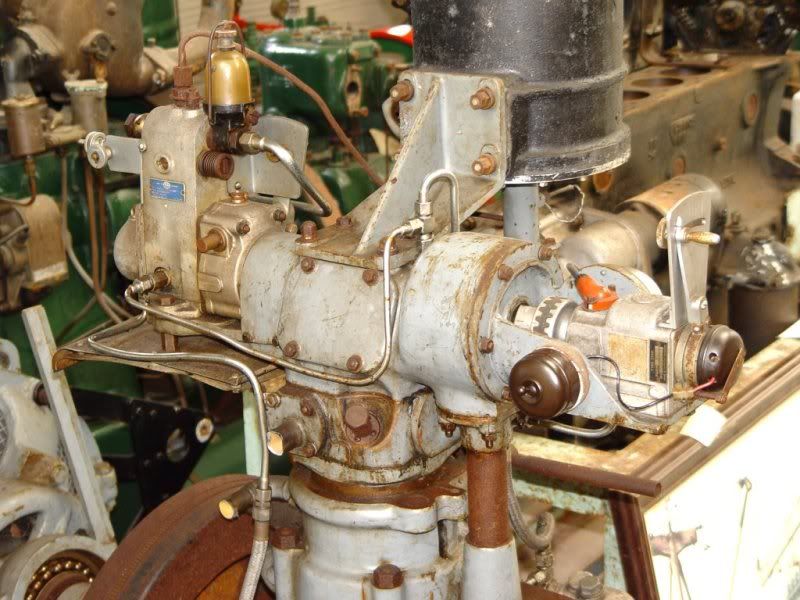 This goes to show how overbuilt the thing is - that massive bracket on the top, is just to hold the air filter! (the big black thing). The part poking out the left is the fuel pump (petrol or diesel, depending which head you fit) and the bit on the right is the magneto AFAIK 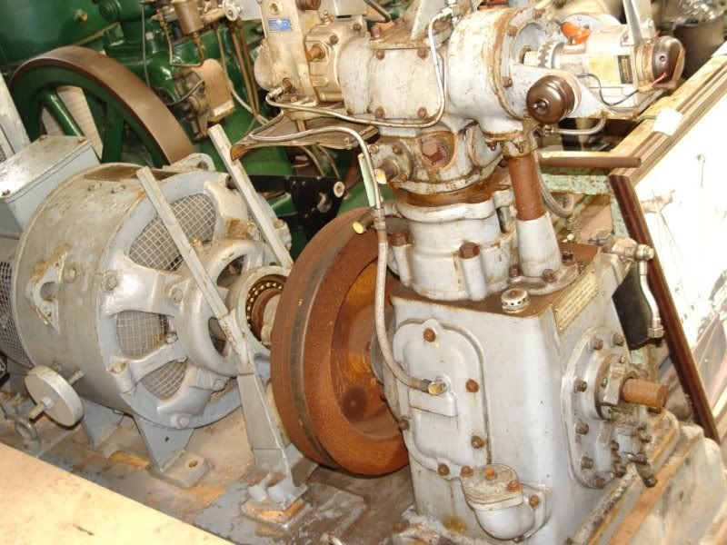 couple of pics of the "interesting" pages from the instruction manual: 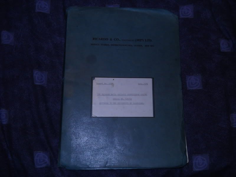  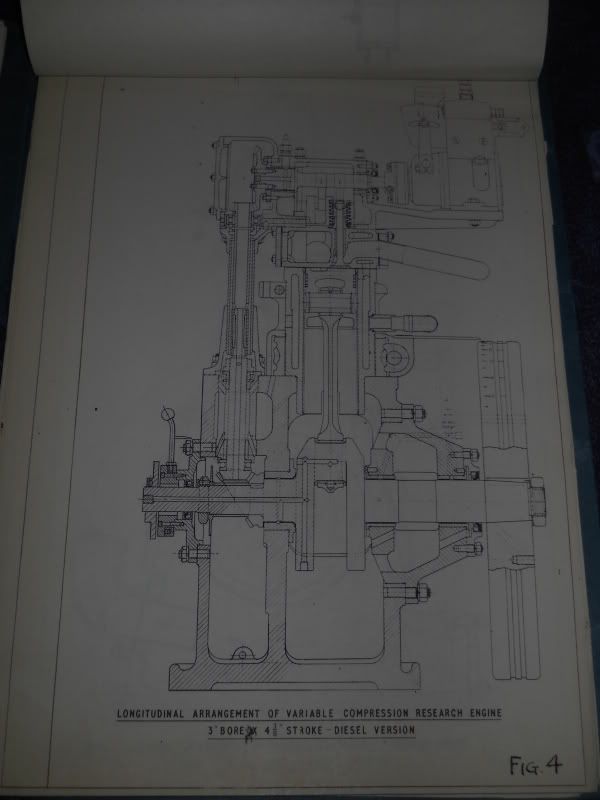 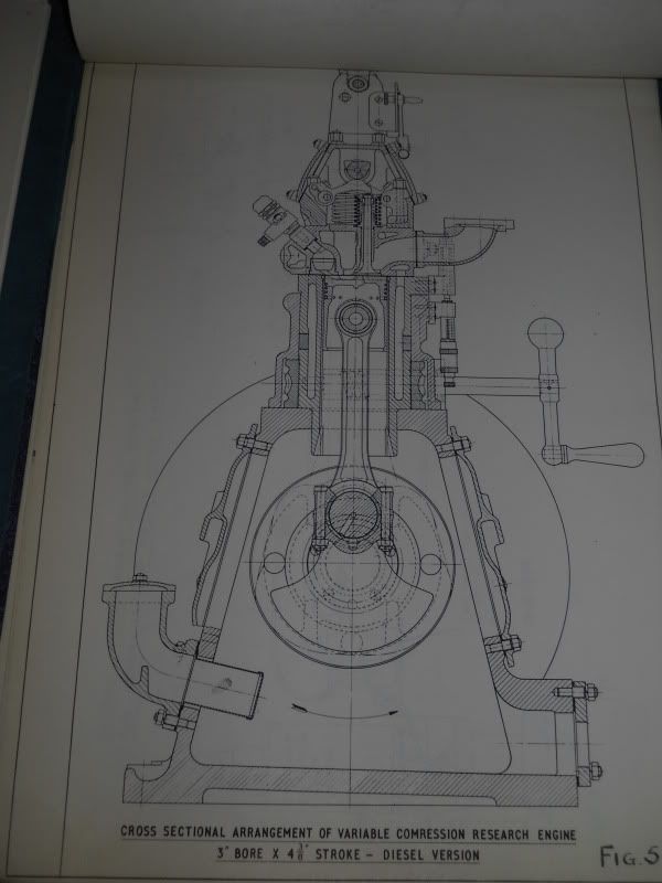 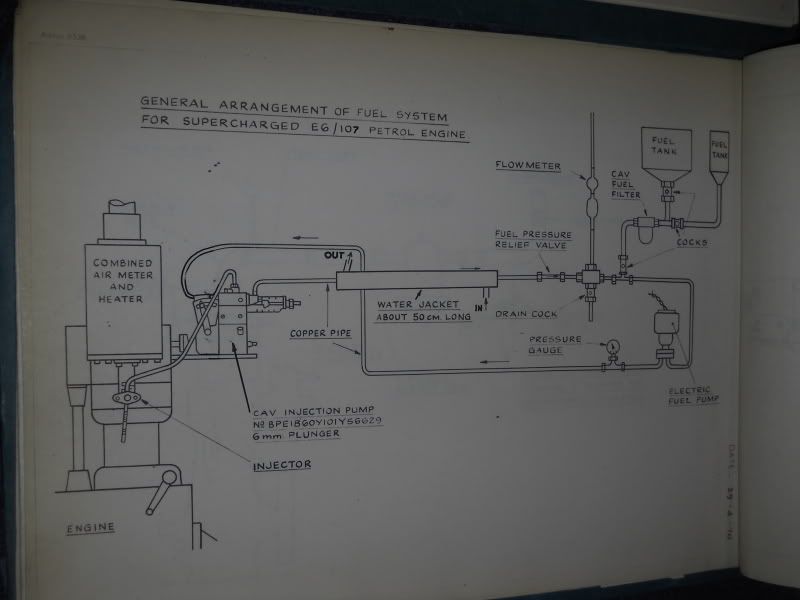 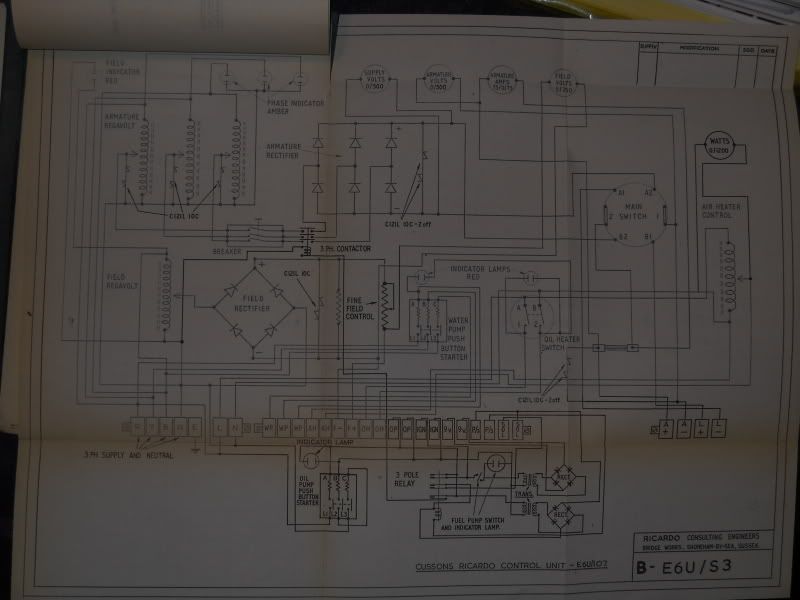 Obviously, if anyone's had any experience with these, your help would be invaluable!  Will get some pics up of the actual unit hopefully by next week |
| |

You're like a crazy backyard genius! |
|
|
|
g40jon
Posted a lot

Posts: 2,569
|
|
|
|
Saw something similar to this a few years ago at a museum I visited in the peak district (so not far from you) found their website, might be worth contacting someone from there www.enginemuseum.org/ |
| |
|
|
|
|
|
|
|
Lol, strangely enough, that's the website I pinched the pics from! so the one above, is the actual one you saw  |
| |
You're like a crazy backyard genius!
|
|
scruff
Part of things
Posts: 621
|
|
|
|
|
Most excellent!
If that wiring diagram is correct it should be fiarly straight forward to trace and repair or replace the wiring.
|
| |
1994 Lotus Esprit - Fragile red turbo with pop up lights.
1980 Porsche 924 - Fragile red turbo with pop up lights.
I spy a trend...
|
|
g40jon
Posted a lot
Posts: 2,569
|
|
|
|
|
how random!!!
|
| |
|
|
|
|
|
|
|
What the diagram doesn't show... is where the MASSIVE oil-cooled resistive load thingie is connected to.... It's easily the size of a chevvy big-block, as it has to dump all the power made by the motor, and be able to do it all day long Looks along these lines:  I'm guessing, wiring this up wrong will result in one of two things happening: A) it won't create any load for the engine B) it'll destroy the windings on the motor in the space of a couple of seconds Plus, the idea of having to vary two analogue dials, and then another selector switch (which I fear, along with the dials, has been chucked out) isn't particularly "high-tech" enough for the uni, to want to let me spend money on that approach. Buuuut, I've just noticed, on the 3rd pic down, the join between the engine+motor is indeed removable, like I'd hoped, and in a nice 3-bolt PCD too Would be easy enough to get a propshaft made to join onto that flange, then direct to the hub-dyno I'm thinking along the lines of a big meaty 3-phase motor to start the motor, and to "motor" the engine (as it describes in the manual), as once disconnected from power, it shouldn't pose any hindrance, and can easily be powerful enough to keep the engine spinning over for continuous periods of time - max rpm of the engine is only 3500rpm anyway. Lol, the more I think of it, the more this is a "get shot of the old tech, replace with new" project  |
| |
You're like a crazy backyard genius!
|
|
|
|
|
|
|
|
Very interesting. How do they seal the head? What was it for originally? Researching fuels?
That wiring diagram doesn't look too complicated. I don't see how they use it as a starter though. Is there some more to it? Like another three phase breaker? (Never mind me. Can see it now.)
I'd be very tempted to keep it mostly as is. As you say there's lots of energy to dissipate and all the heavy iron required to do the job is already there. I think you could turn it into a state of the art dyno by just replacing the gubbins supplying the field current; the autotransformer, bridge rectifier and fine control rheostat. You'd need a PWM controller to supply the current (golf cart ESC perhaps, dunno if they can handle 250V or not) and a computer for closed loop control, monitoring the torque (strain in the arm) and the crank speed.
|
| |
Last Edit: Feb 2, 2012 16:45:18 GMT by Clamity
|
|
|
|
|
|
|
the head+bore are sealed with a normal head gasket - the difference is effected by raising/lowering the head+bore as a unit, from/to the crank. If you look in this pic, you can kinda make out the threaded section on the bottom of the bore. This is surrounded by a large nut, which is then turned by the handle I pointed out in the first set of pics Obviously, turning the handle, turns the nut. The nut can't move up/down, so it instead moves the whole combustion chamber+bore And yups, originally designed to research fuels - but this is beyond what my uni would use it for. Plus it's not just a plain 250vAC, it's a three-phase 400v supply needed (expensive indeed!) The uni already has a pair of VERY expensive pc-controlled hub-dynos, which are capable of 1000Nm.. I'm hoping they can be used individually, which still means 340+lb/ft of torque capacity! So would be plenty enough for this, and means one less (bloody giant!) thing to get in the way. all gauges on the unit are currently analogue, and that means you have to be standing right on top of it to read anything off it - what with health+safety being the way it is nowadays, the university would encourage anything to get people out of the same room that this would be running in.... especially with that 30kg+ flywheel spinning around unguarded!  The thought of keeping it retro, if it was mine, would be the way forwards... but this is going to be pretty much a solo-project by me, with the odd bit of help from the mechanical technicians, programming isn't my forte, and even less theirs! ;D for formula student, we're using an Omex ECU, which is rather versatile, and apparently easy to program. It would make sense for this to be setup to use the same ECU, to justify me doing it. This way, I can say it can be used as a training aid, for programming ECUs, and understanding how fuelling/timing affects knock and power Replace the whole inlet assembly with one of my own design, to use FI. The air filter that comes with this engine, has a big 1KW heater in it, which can raise the air to 80 degrees C - it's worth keeping this, just to simulate what effect temp has on fuelling needs. I'd need to add (so far): MAF sensor Air temp sensor Coolant temp sensor TPS 36-1 trigger wheel Pickup sensor Radiator water pump + oil pump (both electric, not sure if they're there or not?) Normal ignition coil Driveshaft starter motor Thinking about it... it may be easier to simply add another flywheel, with an induction ring already in it, and use the starter motor on that Extra mass won't matter, as it's not going to rev in the slightest! lol |
| |
You're like a crazy backyard genius!
|
|
MrSpeedy
East Midlands
www.vintagediesels.co.uk
Posts: 4,786 
|
|
|
|
Oooooh Now, that's rather interesting Shame you're not nearer, I'd love to have a nose round that. (and maybe a little tinker) |
| |
Last Edit: Feb 2, 2012 18:10:56 GMT by MrSpeedy
|
|
scruff
Part of things
Posts: 621
|
|
|
|
|
Will the omex cope with such low revs? I imagine it idles at 300-500 rpm with a flywheel like that!
I suspect the oil pump is on the opposite end of the crank to the fly and that black container is the strainer and the oil pressure gauge is on the head to the right of the air filter.
I'd guess it'll need an external water pump of some sort, can't see anything obvious, but there is what looks like a water pipes in pic 5 facing the camera and blanked with tape(?)
Keep us updated!
|
| |
1994 Lotus Esprit - Fragile red turbo with pop up lights.
1980 Porsche 924 - Fragile red turbo with pop up lights.
I spy a trend...
|
|
|
|
|
|
|
|
|
oil pump's external - it even says in the instructions that it won't allow ignition, until the external oil pump has reached the minimum oil pressure, and will cut out if it drops below that point. It even points out the push button start for the oil pump in the wiring Should still idle at a normal 800-ish rpm, as it's a fairly normal combustion chamber size (essentially, 1/4 of a 2L engine) it just means it's going to take some time to rev compared to a normal engine.... that doesn't matter in the slightest for what I have planned anyway, as it's never going to have a normal throttle attached to it |
| |
You're like a crazy backyard genius!
|
|
scruff
Part of things
Posts: 621
|
|
|
|
|
Looked at the wiring harder and I see what you mean, how odd, seems strange to rely on external pumps, but I suppose it's an experimental lab engine rather than a power plant.
Oil pump must have sat between the strainer and the sump pickup then.
Would it be easier to stick a crank trigger on the other end of the crank seeing as it seems to stick out near conveinient bolts for the sender mount?
Would be a pity to fully sanitise it of the Heath Robinson stuff, but I suppose that's inevitable given the environment!
Be great if you could have a nice new shiney instrument panel with digital instraments but with the bakalite switch doing something important nailed to it slightly crooked.
How about steampunk-esque nixie tube displays... still digital... ish LOL
Rich
|
| |
1994 Lotus Esprit - Fragile red turbo with pop up lights.
1980 Porsche 924 - Fragile red turbo with pop up lights.
I spy a trend...
|
|
|
|
|
|
|
Managed to quickly get into the workshop today to get a couple of pics of the actual one I'll be working on. A rather nice thing was, it was the Head of the Engineering Department who was in there - I've never spoke to him, apart from literally a passing "hi" as he's walked past me in the corridor.... He called me over by name (this alone surprised me!) and said he was depending on me and one other chap, to pretty much ensure the whole Formula Student project actually gets finished and built on time! So that's a bloody big mojo boost! Had a chat with him about the Ricardo too, and he like the idea of being able to use it as a testbed for ECU mapping, but he still wants to use it as it was intended - including keeping the huge DC motor setup! ;D He admitted the whole motor may need stripping down (!!) to chase the wires, and the selector switch and control panel, has most likely been dumped - which was news to him! But anyway, here's the pics I managed to take - I literally had about 1 minute, as they were locking up the workshop for the weekend, so I didn't get as much time as I'd have liked 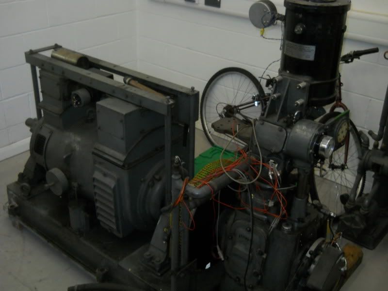 Overall setup - note how much LESS rust there is on this one 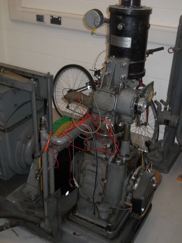 The horizontal pipes are for the coolant, and this one doesn't have the magneto or mechanical fuel pump fitted. The big bulky bit on the end of the crank appears to be the oil pump - at least this means it's mechanical, and not electric! The whole affair is still span over by the big motor, but ignition/etc is only allowed, once oil pressure is suitably built up. 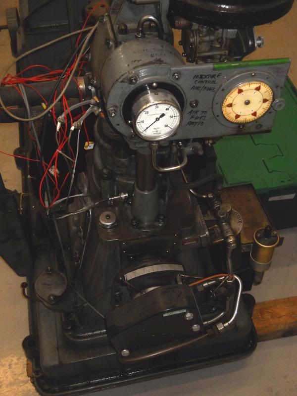 Better view of the end. The big gauge looks like it must be for oil pressure. Zooming in on the piccy, under the lever, on the ally backplate, it says Ignition timing, so there must be some form of dizzy under there - the coil is a generic "Lucas" 12v coil (as specified by the instructions.. which I thought was odd, as it was shown with a magneto!) The cream-coloured dial, controls the mixture screw on the carb. 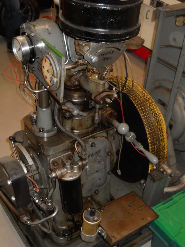 Throttle control is more obvious in this setup, along with the oil pipe routing. In place of the old mechanical injector, is a thermocouple, for measuring the air temperature - but AFTER the fuelling stage? Presumably to measure how much the temperature has dropped, to measure fuel evaporation? The lockoff handle on this engine, is the T-bar shaped bit... which was rather solid! The CR adjustment handle, is far clearer in this picture, possibly due to everything being a different shade, other than brown 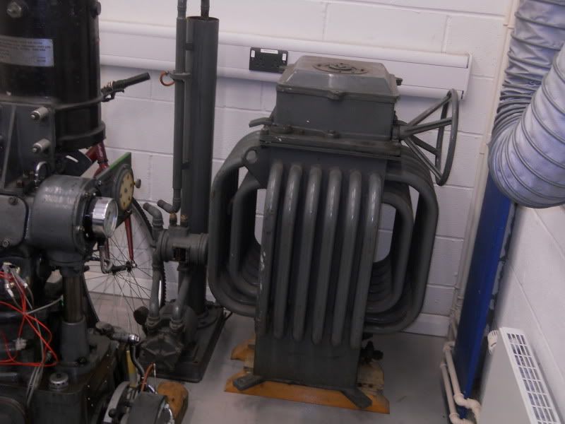 Here's the transformer thingie - not exactly delicate! The grey tube to the left of it, is the cooling tower - rather than cooling via a radiator, like a conventional engine, it simply evaporates the coolant, like a powerplant. He said he'd rather have a closed-circuit cooling system ( radiator), so to make sure it won't overheat, it will have to be pretty large. A low-powered fan will suck air through it, hopefully it shouldn't be too noisy with this overkill setup and lastly... this is what's left of the wiring on the motor: 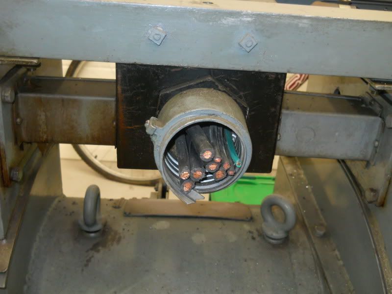 Going to try and get in contact with a few suppliers, to see if it's possible to just order a new control panel? As I said, the Head of Engineering, wants to keep it, exactly as it is, but just add a few more sensors to make it a bit easier to measure output |
| |
You're like a crazy backyard genius!
|
|
|
|
|
|
|
Nice bit of kit - and it looks like a rather later model that the one that you found on the internet: the points ignition and the DC motor are much more modern than the magneto and that open-frame motor. If you can't get a replacement control unit it would probably be fairly simple to recreate it using some basic electronic circuits - it wouldn't look the same though. Word to the wise: don't venture into the dump load beyond the terminal box. The chances are that the cooling oil is PCB-based, which would make it really rather carcinogenic. en.wikipedia.org/wiki/Polychlorinated_biphenyl |
| |
|
|
|
|
|
|
|
Lol, tbh beyond figuring out what connections it has (which AFAIK, should just be two wires anyway) I wasn't going to waste much time on it found a comapany up here in Manchester that supplies new versions of these engines, so thrown an email at them asking what bits they can get me |
| |
You're like a crazy backyard genius!
|
|
scruff
Part of things
Posts: 621
|
|
|
|
|
New ones?!? Wow1
Keep us informed!
|
| |
1994 Lotus Esprit - Fragile red turbo with pop up lights.
1980 Porsche 924 - Fragile red turbo with pop up lights.
I spy a trend...
|
|
kabman
Part of things
Posts: 348
|
|
|
|
|
I remember using these at university in the 80's and, years later, I used to work for Ricardo. These research engines aren't as rare as you might think and are in use all over the world. We have plenty (more modern) ones where I work now. I doubt there's anything I can help you with but it looks like you have enough info there to recommission it without too much bother.
|
| |
|
|
|
|
|
|
|
Well the company I was hoping would be able to get me a few parts (and save me a buttload of time!) haven't even gotten back to me So until I can figure out what the connections are on the main switch... I'm at a bit of a standstill :\ |
| |
You're like a crazy backyard genius!
|
|
scruff
Part of things
Posts: 621
|
|
|
|
|
Pics?
Dunno how much help you want/need but I find that unpicking the circuit diagrams into individual sections usually helps.
Seperate the 3ph, 1ph and DC bits out.
The main switch appears to be in the DC area which makes life a little easier.
The circuit between the Armature Rectifier to the [A+A-L+L-] terminal block seems to be the bit you need. Any sign of the temrinal blocks? Might be worth seeing if you can chase the wiring back to where it starts if you can.
Rich
|
| |
1994 Lotus Esprit - Fragile red turbo with pop up lights.
1980 Porsche 924 - Fragile red turbo with pop up lights.
I spy a trend...
|
|
|
|
|
|
|
|
Have you tried speaking with ricardo at all? They might have a little useful input into the issues i would have thought....
Interesting project btw... will be keeping an eye on it!!
|
| |
Current fleet:
'58 A35 (half mine)
'67 11 window splitscreen vw (half mine)
'77 mini 1000 (not quite 1000 any more!!)
'86 Armstrong MT500
'89 XR4X4
'94 Corrado VR6
Some sort of sevenesque kit car (no age yet!!)
'01 Mondeo estate 2.0 (engine eventually destined for kit car!) - scrapped, engine only left!
'98 E300 estate, rusty but seemingly reliable, fast-ish tat hauler. eventual engine donor
A35 van, or whats left of it after it lived in a field for many years
|
|
|
|


 Will get some pics up of the actual unit hopefully by next week