|
|
|
Sept 5, 2012 18:16:15 GMT
|
Lol, as always - love the comments people give ;D Not got much done today - tried (in vain) to get some big bits of scrap ally to "short-heat", to make them easier to smash up 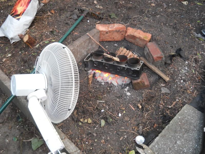 Charcoal pit, fed with a fan, and an old motorbike engine block on top. This didn't particularly do naff-all to the block. I'm assuming the fan, as well as heating up the charcoal, was also cooling the block at the same time  Had a selector rod buried inside the coals however, and that got to the right heat! One smack with a hammer, and it just fell to bits  I wanted to be able to get the fiesta gearbox into smaller pieces too.... but there was NO way I had enough charcoal to do these! 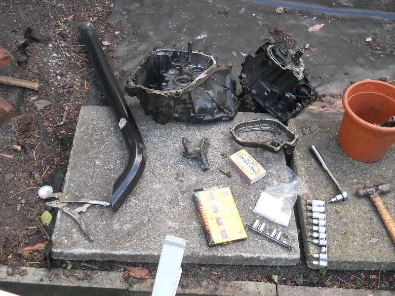 I've also got a transit diesel pump, which is quite a nice sized lump of cast ally too I really need something like a sledgehammer to smash the rest up tbh.... |
| |

You're like a crazy backyard genius! |
|
|
|
|
|
|
Sept 5, 2012 21:02:02 GMT
|
|
So glad you live far away from me.
I could see myself getting into a load of trouble with you if we were to play together..... you could teach me a load of mechanical stuff and I could find loads of "Stuff" to use in your builds.
|
| |
|
|
|
|
|
Sept 5, 2012 22:09:57 GMT
|
Lol, tbh, you know it'd be fun! Hardly anyone around me that likes to play with mechanical things Most of my mechanical skills/knowledge, is from being a pauper, and not having the pennies to afford the right tools or parts.... so I make them instead  |
| |
You're like a crazy backyard genius!
|
|
|
|
|
Sept 16, 2012 0:49:41 GMT
|
Some more progress has been made to the MIG welder! My little PWM motor controller turned up, very tidy. Not bad for a fiver 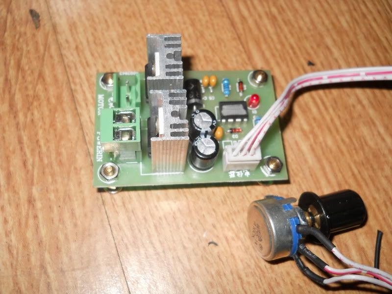 And Just to make sure it worked - slapped it onto the wiper motor. Worked beautifully 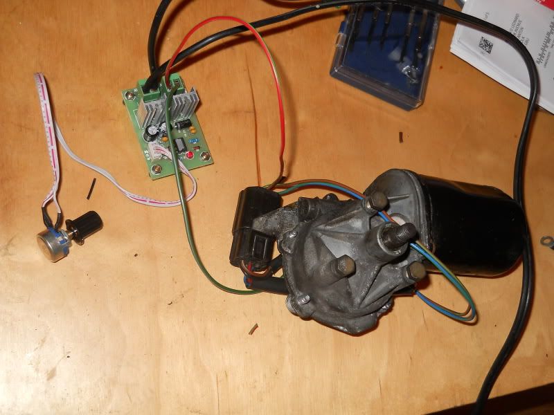 So, onto the task of fitting it into the welder. With the upper side panel removed, this is as complicated at the wiring got.... a rheostat, 12v relay (to switch the 240v relay, that turns on the welding current) and a battery. Hardly high-tech, but it's worked for many a year for me! 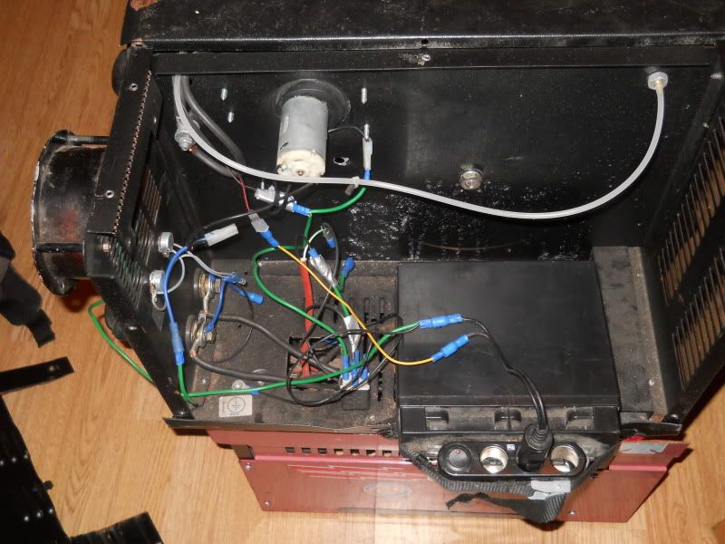 This is with the lower panel removed, and shows just how little space there is in the "power" compartment, and also the big relay 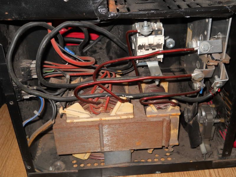 And an overall pic of it "nude" 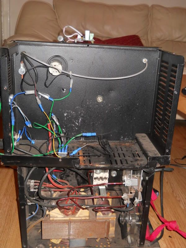 Well.... this lot wasn't going to be of use any more, so out it came! 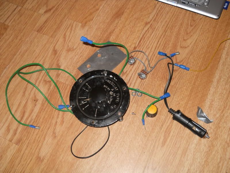 At this point, I realised why the welder seemed so quiet when it was on... the ruddy cooling fan had a wire loose! Plugged it back in, and made sure it still actually worked, and that I hadn't actually just forgotten removing it, because it was faulty - it was still good! 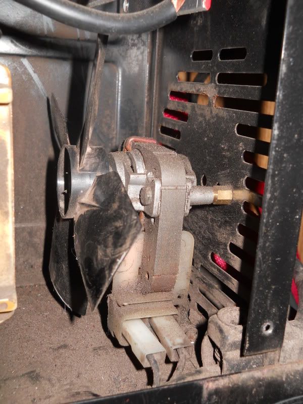 Next... I needed POWWAAA!! Next... I needed POWWAAA!!  I molested an Xbox "power brick" and did this to the end that connected to the Xbox. Connect the single 5v wire, to the power check wire, and it gives 12v,with 16.5A supply! 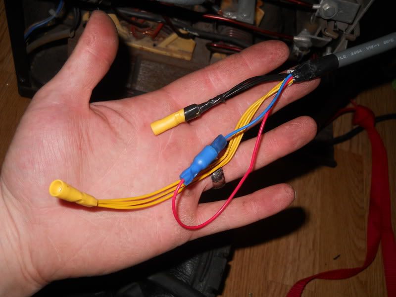 I fitted a second relay, so all the current for the motor, wasn't going through the diddy switch in the torch handle. Tidied it all up, and voilla! 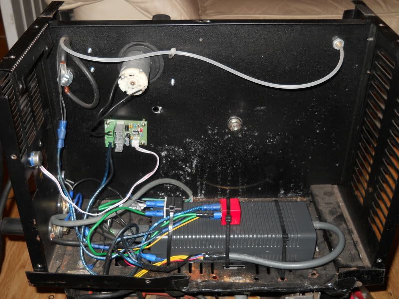 Need to do something about the hole now left in the case (maybe?) And sort out a bigger potentiometer, as the one supplied with the controller, is ruddy TINY! 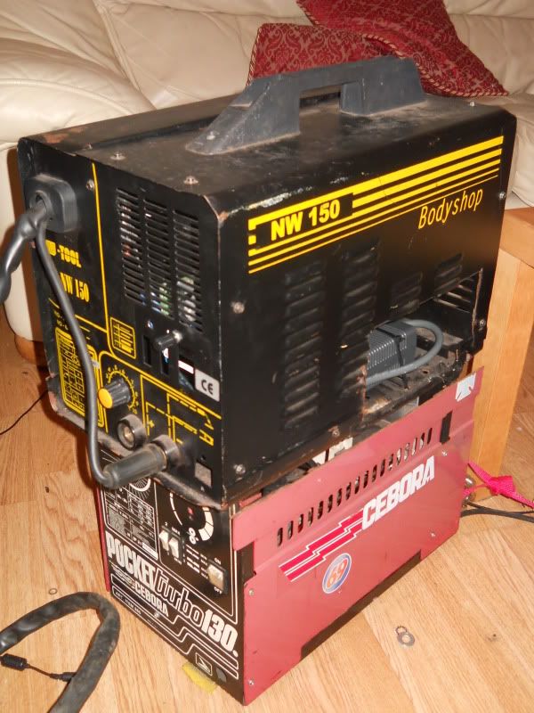 The black+yellow dial was the original one... Wouldn't mind using that dial+hole again tbh. Maybe in a month or so.... In other news, I picked up a load more stuff from back at my parents - including the blower for my furnaces (a modified mini blower) 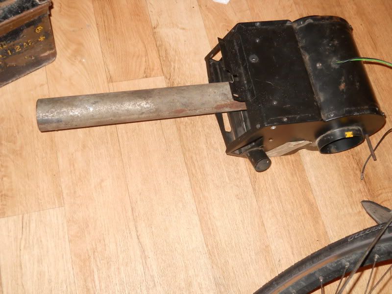 My ARC welder, along with a TIG torch, and a handful of bridge rectifiers...... With a few other parts (all thrown into the small ammo box!) I'll have a pretty decent DC TIG welder 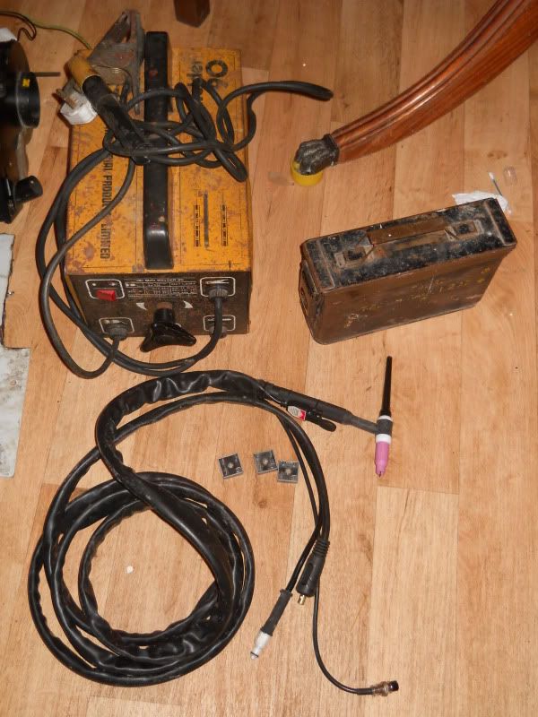 The next step, would be AC control for aluminium welding, and a high-voltage auto-start But what I'm mainly happy about: I now have a full compliment of tools again!!! ;D 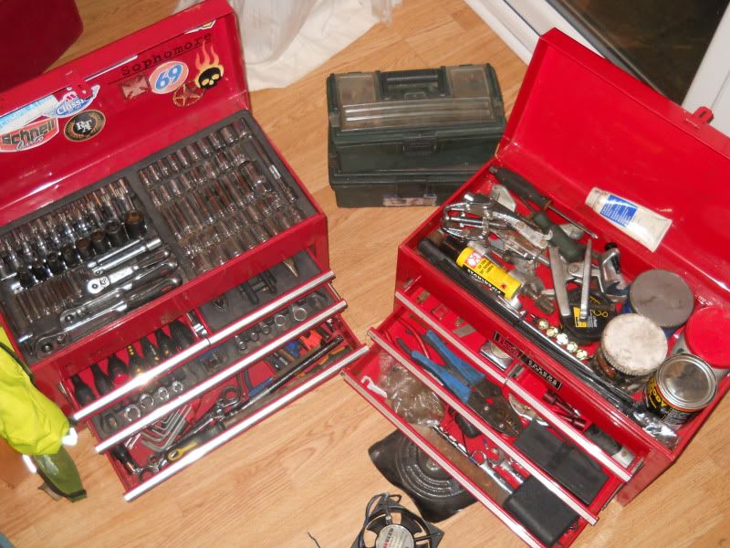 For the last year, I've basically only had a "condensed" toolkit, that squeezed some sockets/screwdrivers into the two small green boxes in the background. SO happy to have all of them again! Tomorrow: Pulling the ARC welder apart, to see how much space is inside  |
| |
Last Edit: Sept 16, 2012 0:52:39 GMT by chairchild
You're like a crazy backyard genius!
|
|
dog296
Part of things

Posts: 302
|
|
Sept 16, 2012 7:26:50 GMT
|
|
Nice to see scrap is keeping you happy
|
| |
|
|
|
|
|
Sept 16, 2012 7:42:33 GMT
|
|
So much fun! You don't get that with a multi-thousand dollar account down at the tool shop. Maybe I'll have to start looking for knackered MIG welders to fix up. I haven't got one at the moment, was planning on waiting for a few months and then buying a nice shiny new one.
|
| |
|
|
|
|
|
Sept 16, 2012 16:30:08 GMT
|
Dog... why are you on here, shouldn't you be on hols in vegas?? Or do you miss me that much? Had the ARC welder apart quickly, to see what I had to play with 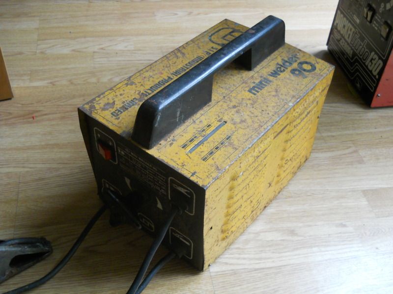 Methinks I'll need some more screws to hold it together mind you... these 4 tiny things were all that held the cover on (and you lift it by the cover!) 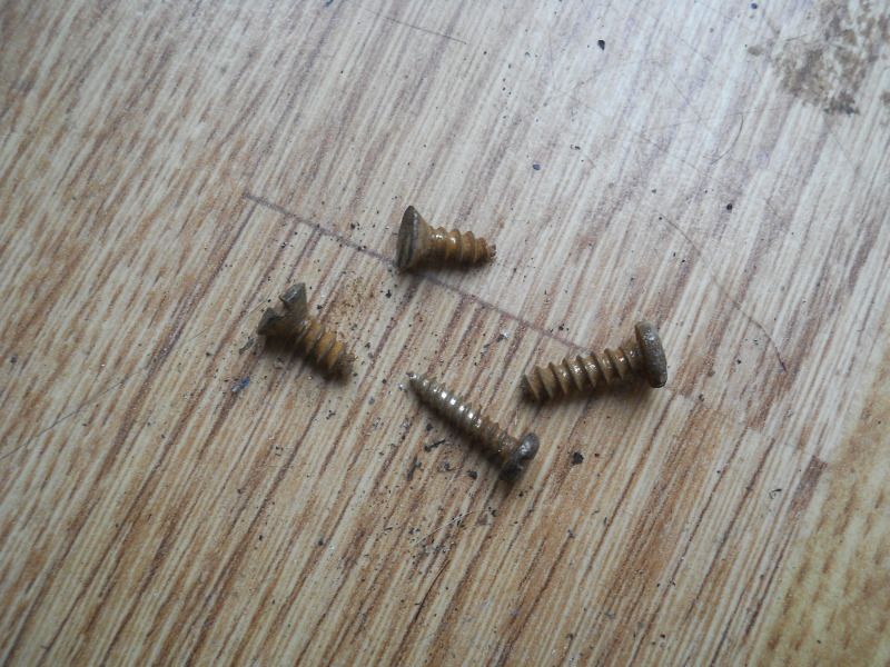 Was nicely surprised by how much apparent space was in there! PLENTY of space for my upgrades, and the addition of a cooling fan 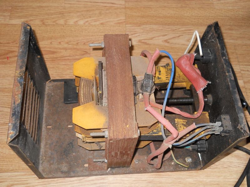 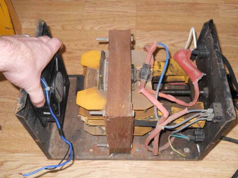 Then I remembered... the core moves Lowest setting: 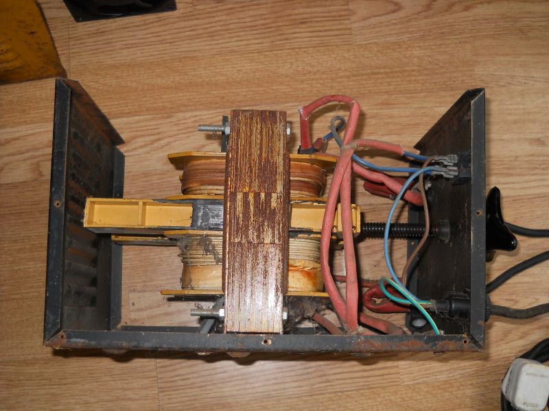 Highest setting: 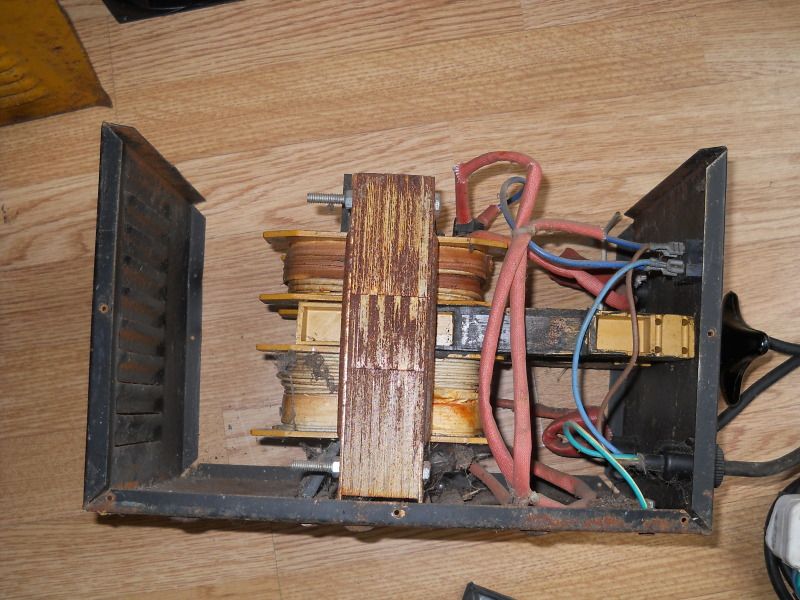 So initially... no space whatsoever But... If I limit it to 30A at the lowest (as I doubt I'd EVER need to go lower, as I have no intentions of welding tin-foil!) Then there's just enough space for the fan to fit 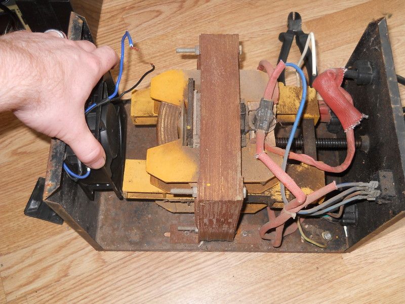 It's a simple AC output, so I plan to rectify it to DC with some nice cheap bridge rectifiers. As it's only a 90A output, three 35A rectifiers will give plenty of headroom, without overheating too much (they'll still be attached to a hefty heatsink mind you) And I'm going to need a "choke" to smooth out the voltage ripples - this is essentially a big transformer, with just a big primary winding The way you "read" the power setting, is rather basic, and due to the age of it, is getting pretty hard to see. Attached to the moveable core, is this big bit of wire 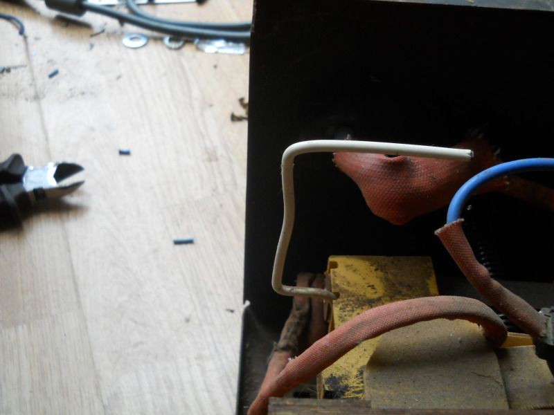 Which you look at, through this hole 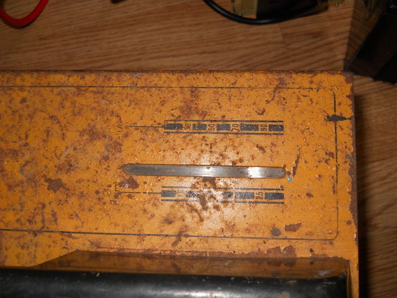 The plastic is MORE than showing its age though 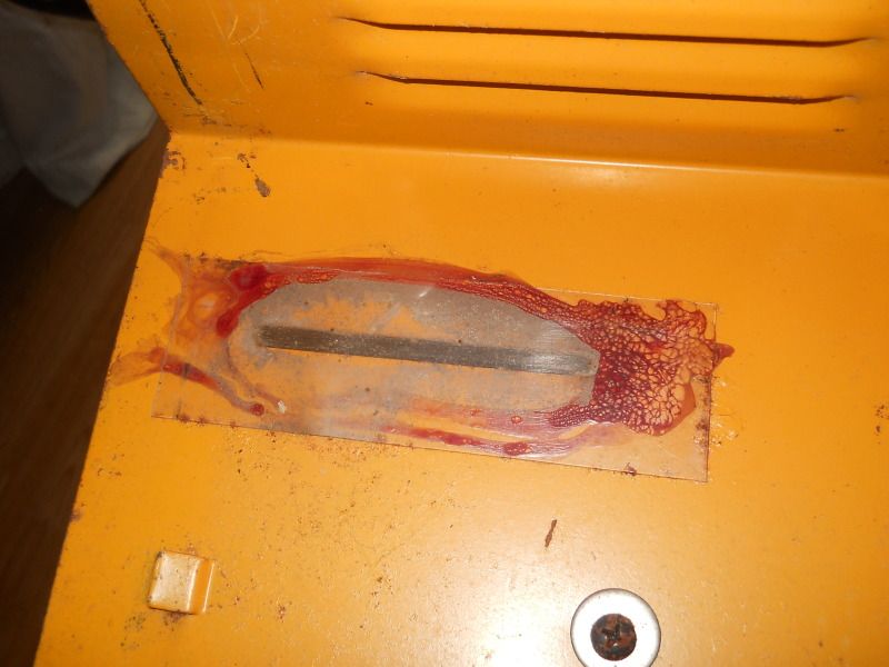 So, will most likely replace the plastic, and install a small light (LED?) that will reflect off the white wire, making it easier to see A "future" mod to this, will be to set the core to maximum current, and leave it like that (remove the handle/etc) and instead,control the output with a variable core: aaawelder.com/reactor.html Basically,with no DC input, the output is massively reduced. Once you reach a high enough DC input, you increase the output current to maximum. A simple dial will give me proper current control, rather than turning the huge wheel millions of times! I'm not sure if the existing case is actually going to be of any use for upgrading, as it's VERY compact, with no real space to spare. An old MIG case would be a good donor, or I may find something else to do the job |
| |
You're like a crazy backyard genius!
|
|
dog296
Part of things
Posts: 302
|
|
Sept 17, 2012 6:12:25 GMT
|
|
The time here is currently 23:11, I can hear V8's rubbing and Harley bikes crusing the strip.
I can't sleep for toffee, so thought I'd check out the crazy curse word your upto without me to rant at lol.
Don't worry, I'm back on Thursday lol
|
| |
|
|
|
|
|
Sept 18, 2012 14:15:33 GMT
|
|
very interesting thread dude, and has provided much laugh out loud moments, siome very ingenious plans man! i hope they all work as planned
|
| |
|
|
|
|
|
Sept 23, 2012 13:42:40 GMT
|
Went and saw my project supervisor today - dear god he's got a LOT of toys to play with! But... in the back of one of his T25s, is this small collection: 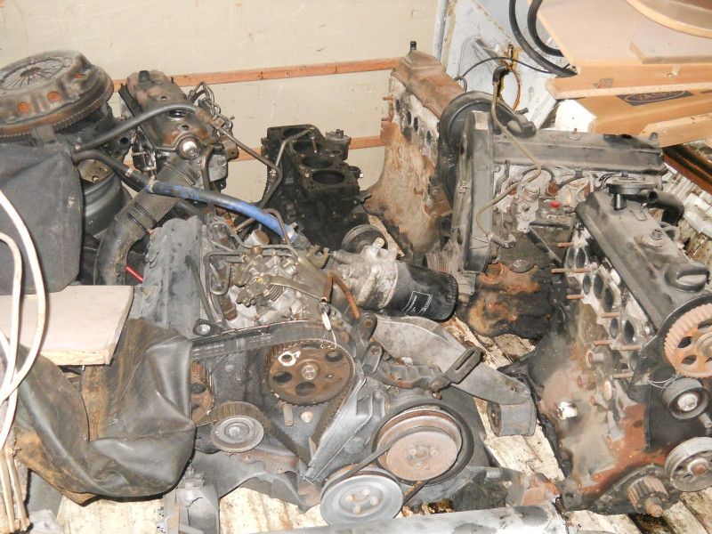 The engine in the bottom left, was literally dripping oil from the exhaust when running, so is "dead". The one to the right of it, is stripped of all main parts, but should be a good one. So come next sunday, we're going to strip all the parts off the "dead" engine, slap them onto to the other one, fit a mechanical VE pump - then take it into the workshop at uni, to rig upto the hub dynos they've got! But... as we don't really want to use the gearbox (why measure the losses of the gearbox, when we don't care about them?) I've also been given the task of designing a method of sending the power from the flywheel to the TWO hub dynos (the don't work if you just use one, for some reason) So,we're thinking of something along the lines of a live axle, bolted straight to the dynos, then a small propshaft (of some description) direct to the flywheel, with an adaptor plate. A diesel bellhousing will be fitted, so the flywheel is covered (health and safety...yawn) and so to locate the starter motor Adaptor plate may be something along the lines of this: 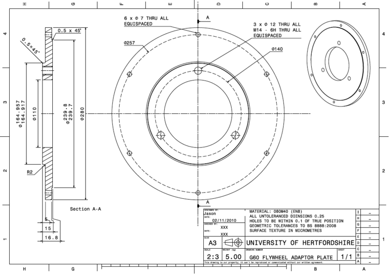 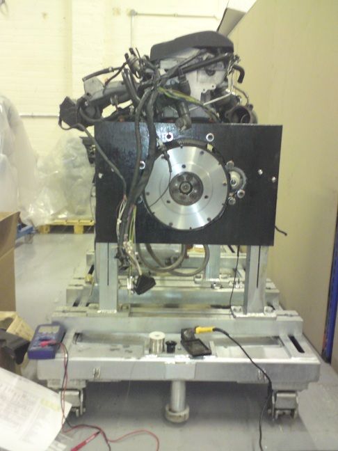 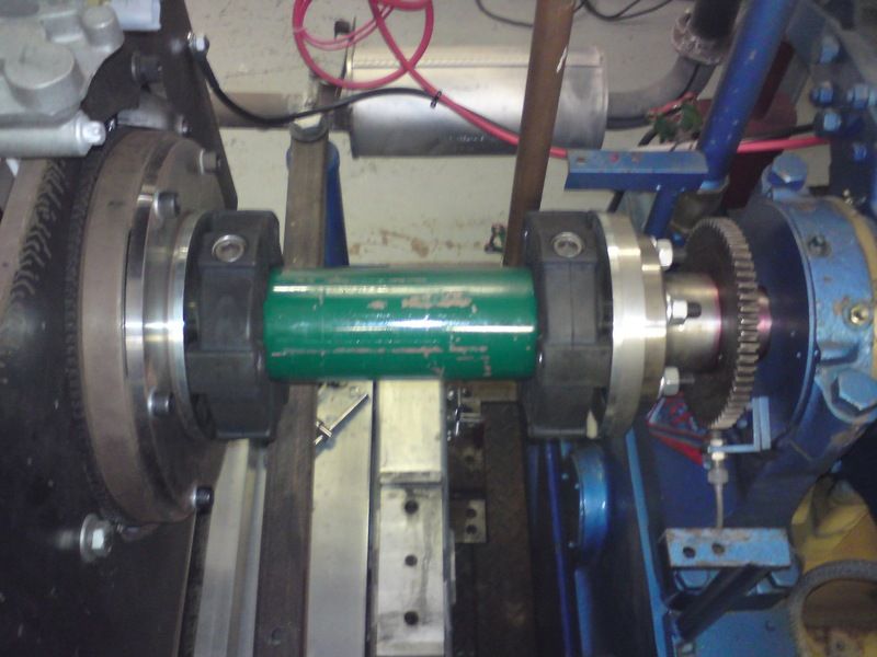 |
| |
You're like a crazy backyard genius!
|
|
|
|
|
|
|
Sept 23, 2012 16:34:00 GMT
|
Love your recycling attitude.. ;D I will be watching your ARC/TIG welder build with interest.. It's making me wonder why I chucked my old dead ARC welder out  Your stack of MIG'S reminds me of old times when I worked in an animal rescue center in Biggin hill... The lounge in the staff quarters had two tv's.... One for picture and one for sound |
| |
Last Edit: Sept 23, 2012 16:42:53 GMT by Stigian
My YouTube Channel www.youtube.com/user/UkWheelHorseBlokeQuote - D'you know, it's people like you, doing totally brilliant and pointless stuff like this that gives me a little hope for humanity |
|
|
|
|
|
|
Got a bit more work done yesterday - sorted out the engine that's going to be used. A VAG 1.9TD, made from various VAG engines my tutor had lying around! Lol genuinely couldn't tell you the source of any of the parts though Started off with the bare lump: 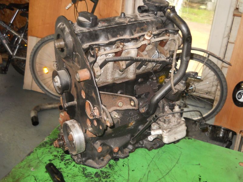 The choice of exhaust manifolds alone! Lol, I can truly see why people love to play with these engines! 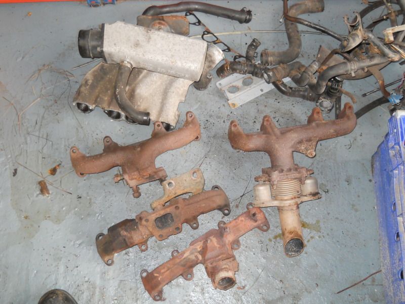 Built up, and off for steam cleaning! 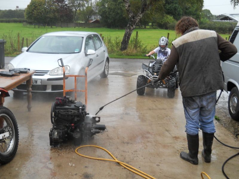 Still need to sort an injection pump out - he's thinking of sourcing a 200TDi pump, and getting the machining work done at uni (rather handy that, lol). We've also hatched the plan of the following testing: Dyno run of the engine in N/A form, then with the standard turbo, and then with the vnt. This means we'll have the "worst" power, and standard power. As long as the VNT power output curve is nicer than both plots, it's all good! Lol So as part of that... I need to mix and match parts between these two turbos to get one good one: 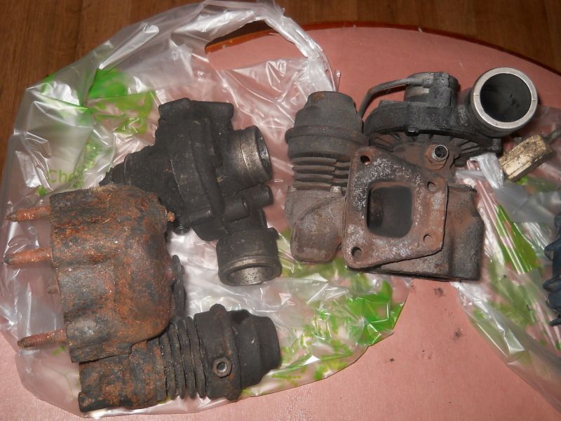 Oh... and what's that behind them? 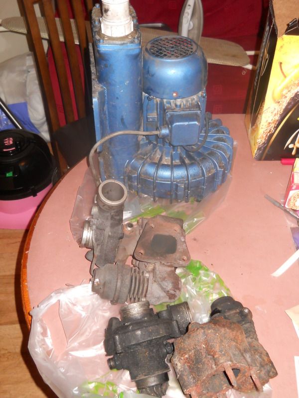 That's right... a bloody MASSIVE air pump!! 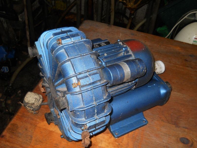 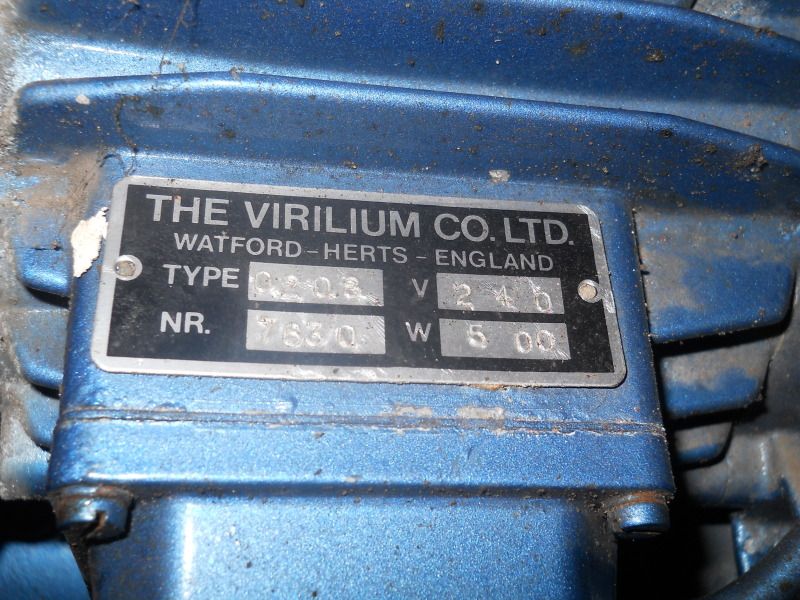 The plan for this, is to use it as a form of flowbench, to set up the minimum vane angle on the VNT, to give the same backpressure as the OE turbo. Hopefully, this will mean it will spool up at the same rate as the OE turbo (very little point trying to get it to spool earlier). So, Lets have a closer look at these turbos eh? First up: The "good" core, with the knackered turbine wheel, and hotside. Whilst the turbine itself was fairly butchered, the core had good bearings - very little play. This pic shows where the turbine wheel has been rubbing on the turbine housing 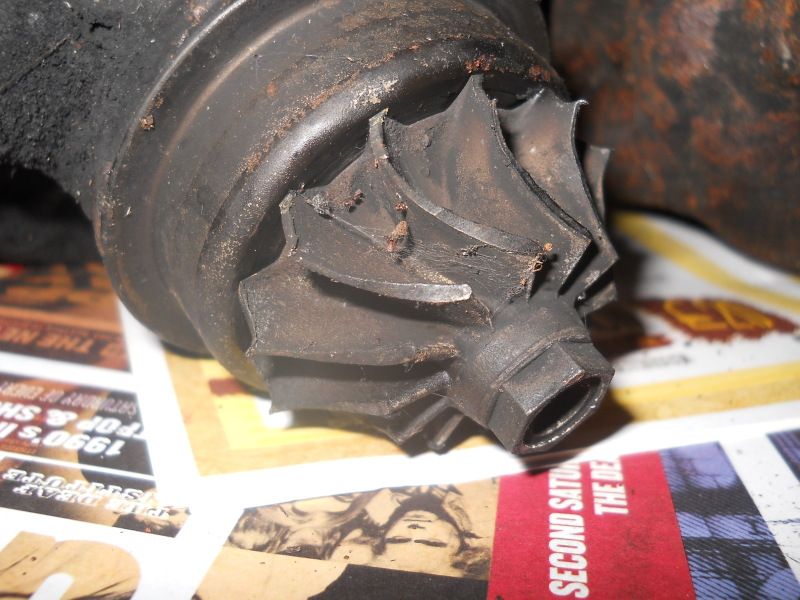 The compressor wheel however, was in much better condition than the other turbo - so this was going to be saved. The other turbos bearings, were TOTALLY knackered, but the turbine wheel, and housing, where (apparently) in much better condition. I think it's safe to say, the oil wasn't staying where it should do... 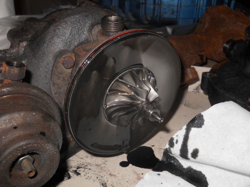 A little pic of the workshop (aka: dining room table) 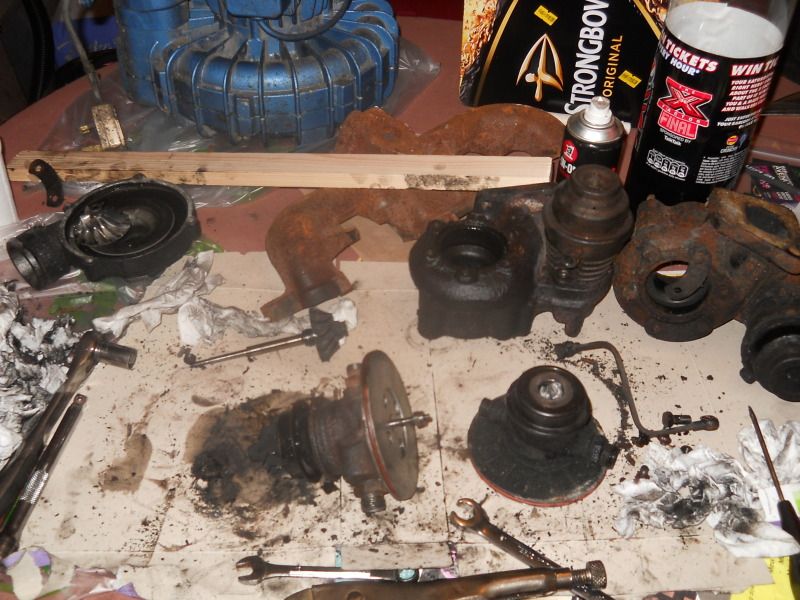 After swapping this turbine + shaft, into the "good" core, along with the better compressor wheel..... I noticed this on the turbine wheel 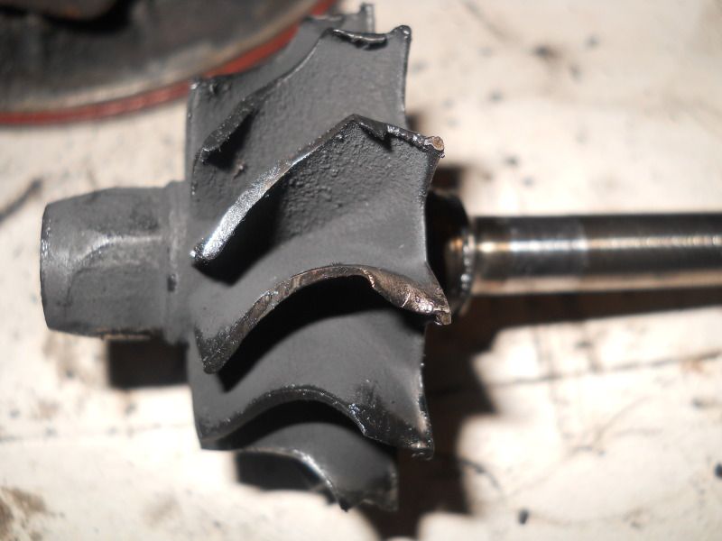 Awww.... curse word Ah well, it's in now. It's only got to make one or two "power" runs, to give me some baseline figures anyway. So, now that's sorted, on to the seized air pump! ;D When we first picked it up.. a good litre or so of water promptly poured out from it. Turns out his shed had semi-flooded a week or so ago. Not a particularly good sign if I'm going to be honest. So, whipped off the easy bits first. The power connection cover: 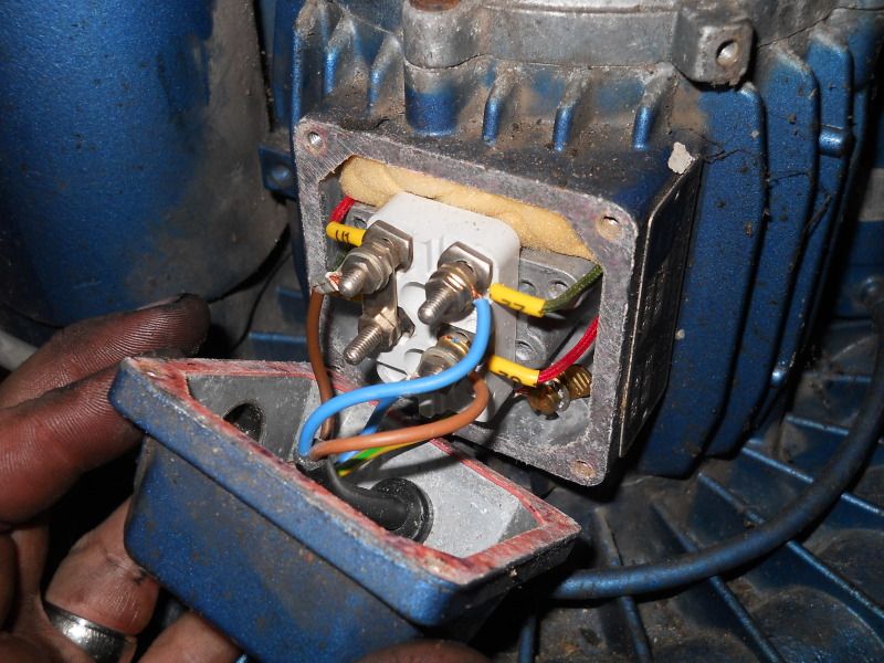 All dry. That's a good thing! Lol. How about the end cap of the motor? Is the inside of the motor dry too?? 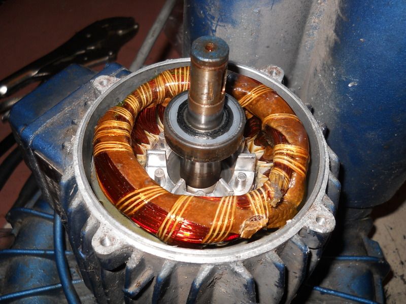 Thank god (actually doesn't look bad at all!) Now onto the only bit that's left, the main compressor! This was quite a battle to separate the two halves, but it eventually succumbed 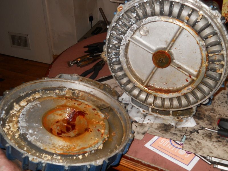 Well I think I've found the problem So whatever water was in there, has caused the aluminium internals to be covered in more fuzzy stuff, than a Russian mob gangsters wife. The bottom half is just a guide for the air - the upper part is the "pump" that's connected to the motor shaft. The whole thing's corroded around the edges to the outer case.It REALLY doesn't want to move right now..... resist it may..succeed..it shall not |
| |
You're like a crazy backyard genius!
|
|
|
|
|
|
|
I left you all last time, clinging to the edge of your seats, now for the next instalment of bodging! In the middle of the pump, there was a small securing plate, not that it was needed, as it was VERY tight on the shaft it turned out! 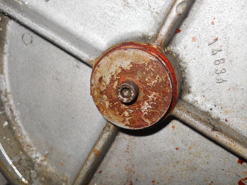 Remove the plate, and it revealed two threaded holes - I used these to make a small puller at uni with 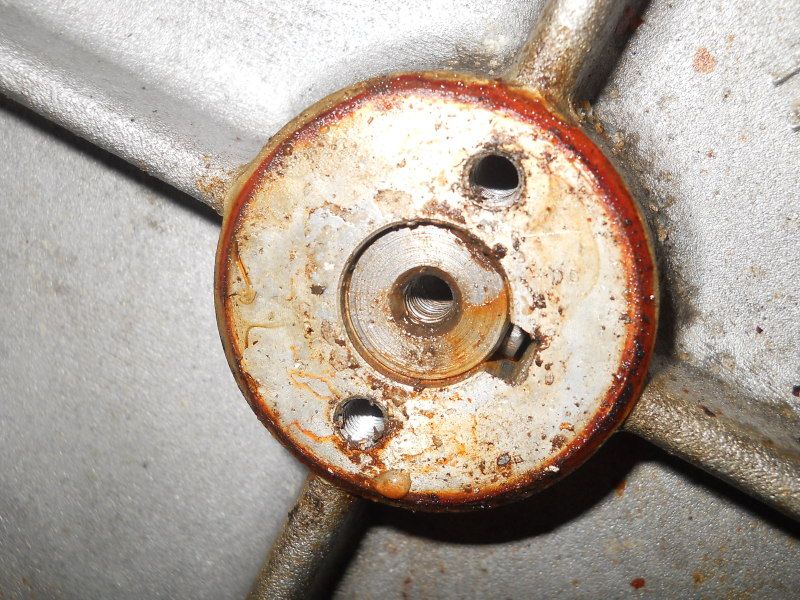 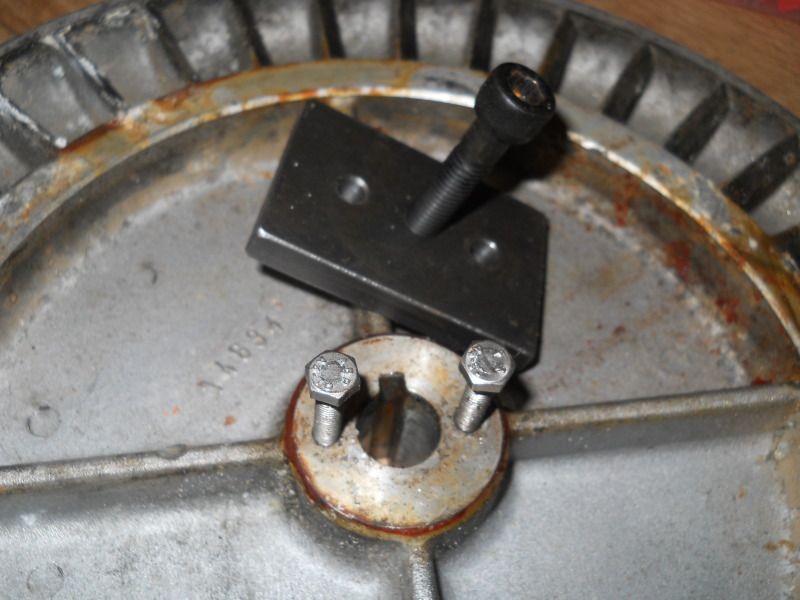 But I wanted to loosen it before trying the puller, as they were very small for the task they had to do! Got the fan turning with a block of wood, and a good few smacks with a hammer Wasn't the smoothest due to all the corrosion, so it 100% had to come off either way It was a bit of a battle, but it eventually gave up! And dear god it was thicker than I thought! 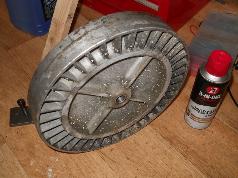 So stripped it all apart and gave it all a clean in the sink, getting rid of the worst of the corrosion and crud. 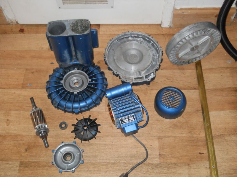 Bit of a weird construction though - the pump housing was part of the motor itself, holding one of the bearings 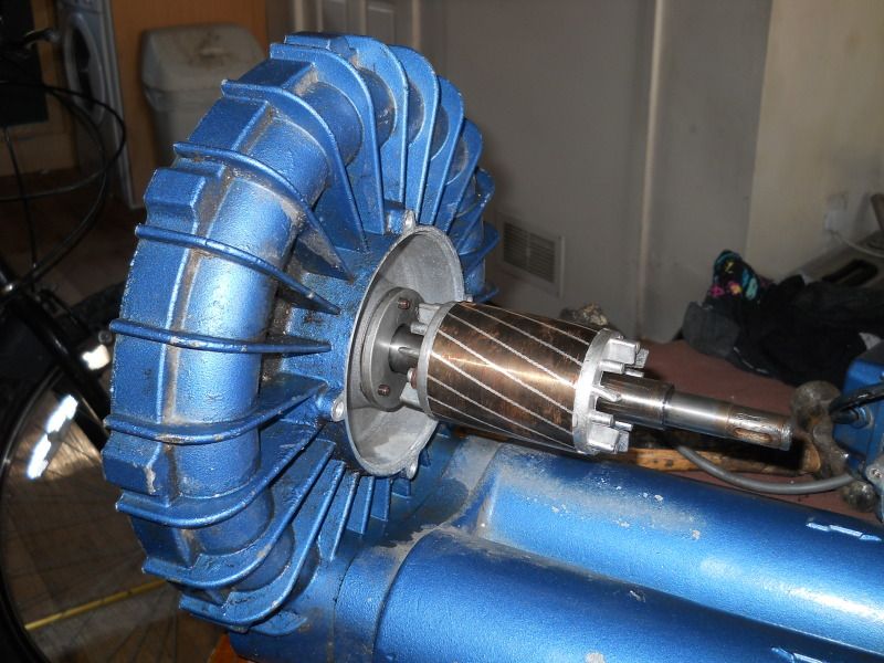 Putting the fan back on the shaft was a bit of a ballache too! Had to pull it onto the shaft with the singular M4 thread in the shaft! It wasn't too pleased about this, and showed its disgust by snapping the bolt! 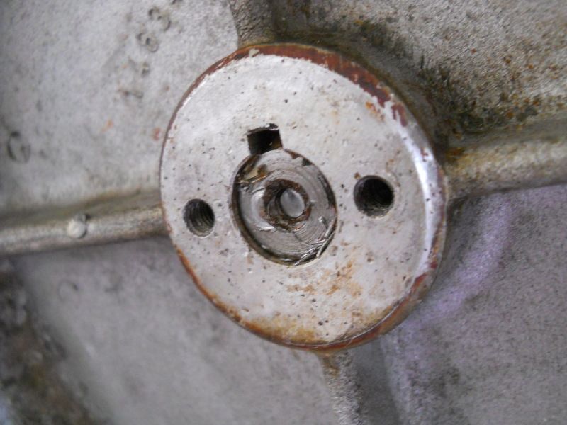 Well... lets hope that little plate that was held on there, wasn't essential (eek!) So, cleaned up, slapped back together - and the fan turns easily in the housing! Until you put the front plate on... at that point it's seized solid once it's pushed on (let alone tightened up!). From what I can tell, it's several small spots of corrosion that are in the cover. They're possibly only about 0.2mm thick, but as the whole thing runs with VERY high tolerances, it's enough to seize it up So... I need sandpaper! Lol |
| |
You're like a crazy backyard genius!
|
|
|
|
|
|
|
Took a file to the faces of the fan as it was spinning, and a scraper to the inside facesof the housing to get rid of the buildup that was stopping it. It now works! |
| |
You're like a crazy backyard genius!
|
|
|
|
|
Oct 14, 2012 15:00:28 GMT
|
Finished making the "flowbench" and got some readings from it This has been set up as a "positive pressure" flowbench. Meaning all that it's really good for, is direct comparisons, rather than calculating actual airflow. But this will do me fine. Firstly, I needed a way to measure the pressure accurately. So for that, I took the 2.5 Bar MAP sensor off my car - it never came with one, so I fitted it with some 5v regulators,which made my life rather easy for this 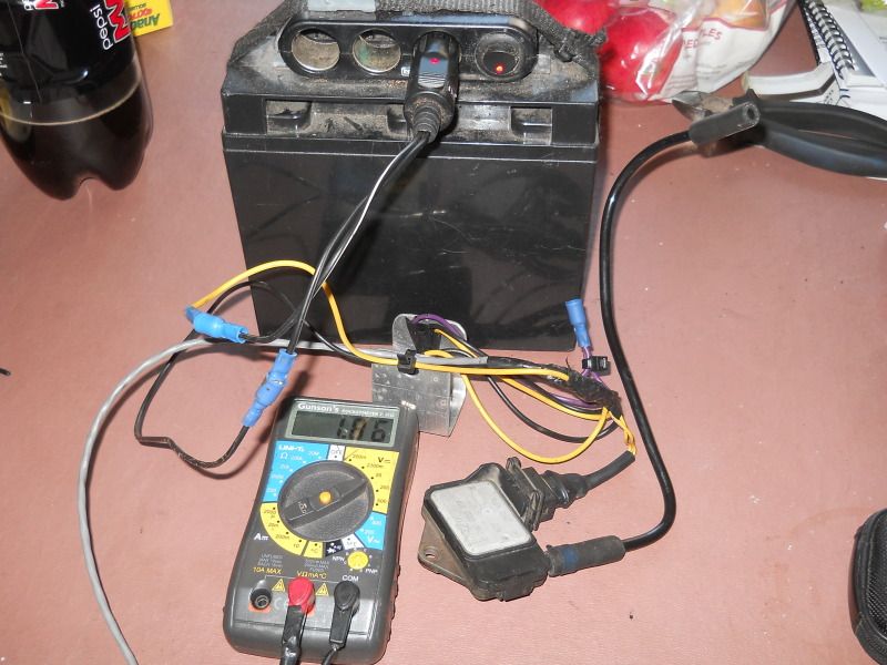 At atmospheric pressure, it reads 1.87v. For my car, this would need to be changed to an actual value. In this case, it's just being used for direct comparisons, so units are meaningless To get an accurate measurement of pressure, I made a little fitment that was a snug fit on the outlet, and was out of the direct airflow 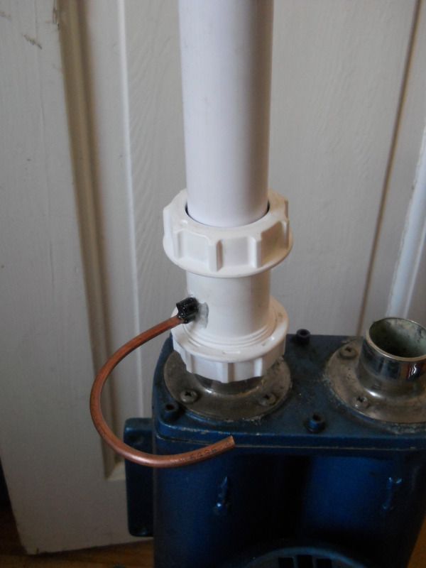 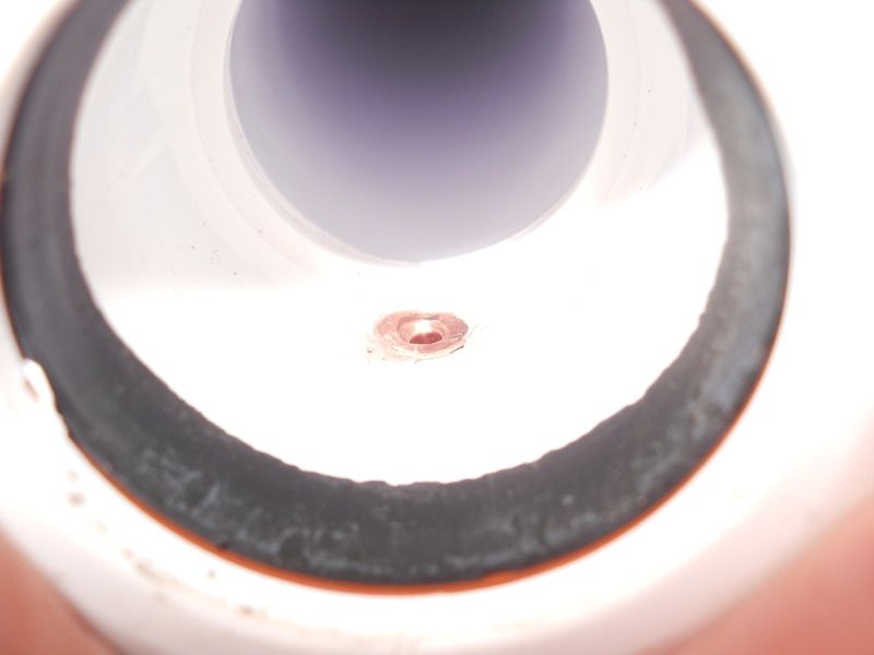 And with the MAP sensor plumbed in 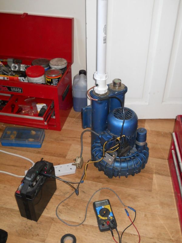 The original plan, was to get some acrylic adaptors cut at uni, to ensure perfect alignment to the pvc pipe. But I'd have to wait approx 2 weeks for that. Plasticine was used instead So with the pump on, but unrestricted, I got the "base" pressure reading of 1.87v. Perfect! Zero restriction, so it's just reading atmospheric As soon as I clamped the end shut with my palm, I got the max reading of 2.22v So all my readings will be between 1.87v, and 2.22v. Not a huge window I'll admit, but it will do With the tiny Rover turbine, I got 1.96v The vw 1.9 turbine got 1.93v so from this, I can instantly tell that the vw turbo flows more than the Rover turbo, as it has less backpressure. Now for the VNT the GT1849v got two readings - one for when the vanes are fully open, and one for when they're fully shut. The fully shut position however, can be adjusted - which is the whole point behind this exercise. I want to be able to have the smallest position the same as the OE turbo it would be replacing, to mimic the same response time, and prevent "choking" the turbine. So, for fully open, it read 1.89v and fully shut, it read 1.98v So what this tells me is, at fully shut, it's actually smaller than the Rover turbine - so it could theoretically spool MUCH faster, at the cost of extreme backpressure if it was to accidentally shut at high load. Conversely, at fully open, it's closer to atmospheric, than either turbine. So boost control would be rather effective, if it was to open the vanes  The next stage, would be to get the adaptor plates made up, and get some more accurate readings - before setting up the VNT turbo, to closely match the VW turbo I've also got a mate with a GT2256, that we want to match to the Rovers turbo - his minimum setting hasn't been touched, and I'm sure there's some low-down response we can get from it I also "cleaned" an old intake manifold for my car - the EGR mixes with the breather fumes, making a gungy mess of the intake. Normally you'd either use a pressure washer, or a parts washer.I had neither. So I wedged a couple of BBQ firelighters into the manifold, and set fire to them 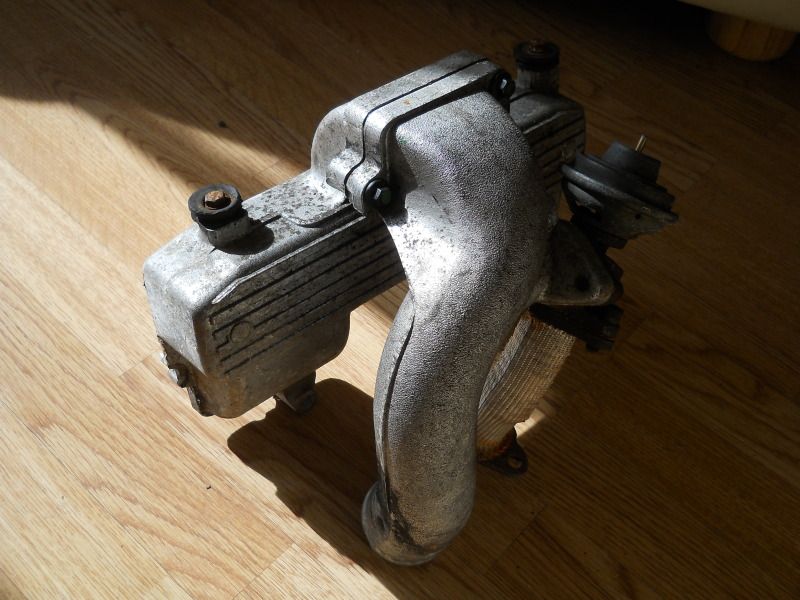 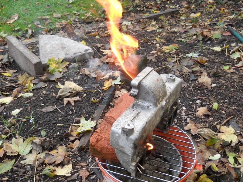 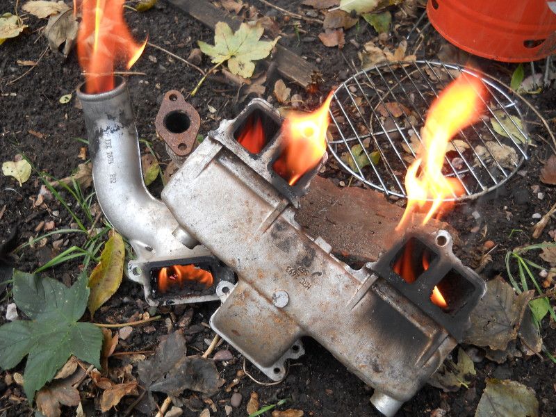 In the last picture - the firelighters have gone. It's purely burning the oily gunge! When it died out, I doused it all with a hosepipe, gave it a few smacks on a brick to get all the burnt crud out - and it was FAR better Not perfect, but 90% of all the gunge had gone. A quick dousing with degreaser would get rid of the last bit.... but that will have to wait for when I get a donor 200TDi intake manifold, to butcher them together |
| |
Last Edit: Oct 14, 2012 15:07:18 GMT by chairchild
You're like a crazy backyard genius!
|
|