duncanmartin
Club Retro Rides Member
Out of retro ownership
Posts: 1,320
Club RR Member Number: 70
|
|
Aug 21, 2016 19:14:54 GMT
|
This thread will be stealing posts from another place, but I figured it would be right up the RR street. Please let me know if you want more detail...  I'll try to answer any questions without infringing on the instructions I used (if you want to do it, just buy a set of plans, they are super detailed and super cheap!)! I've wanted a Windcheetah ever since I saw one in the Richards Bicycle book aged 10 or something! Then at the start of last year I discovered AtomicZombie, and started on the process of building a StreetFox (but with disk brakes, 20" rear wheel, and a few extra modifications, including a fold in the middle). This isn't necessarily a "bodge", but there are a few along the way! I'll update this thread with my progress so far - I've not completed it yet, but I've made a lot of progress! This is what it's supposed to look like when done:  This is what I started with - the bikes in the top photo were knackered and free, but the suspension bike cost a whole £15: 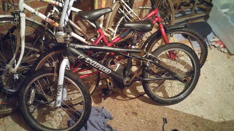 20150114_185607 20150114_185607 by duncancmartin, on Flickr  20150118_183431 20150118_183431 by duncancmartin, on Flickr So, off came the rear triangle - this will be used almost entirely as is.  20150124_124346 20150124_124346 by duncancmartin, on Flickr But the rest of the frames didn't survive so unscathed - here are the headtubes and the pivot for the rear triangle (angle grinders are great!):  20150124_141729 20150124_141729 by duncancmartin, on Flickr And here they are all cleaned up with the chopped up forks to go with them: 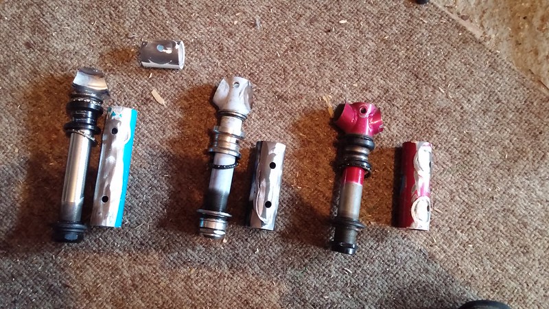 20150125_135603 20150125_135603 by duncancmartin, on Flickr At this point, I decided (don't know why) that I needed significantly more travel than could be provided by the crappy shock that was on the kids bike, so this arrived: 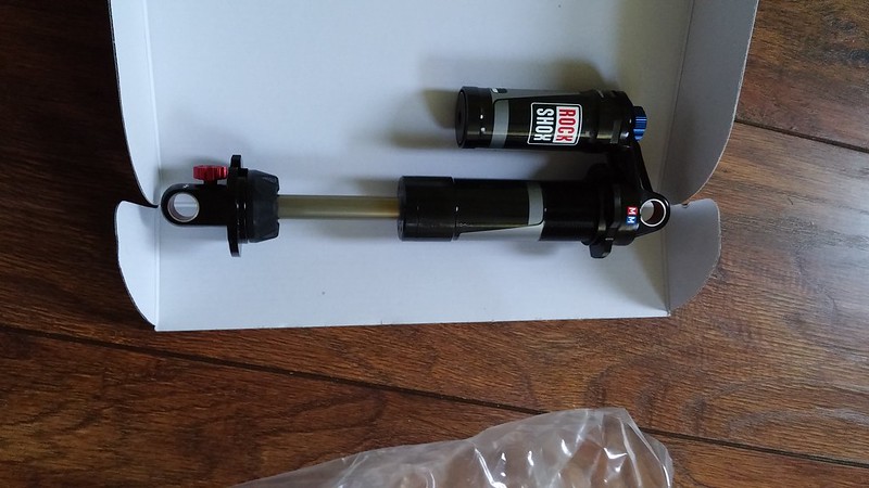 20150124_160615 20150124_160615 by duncancmartin, on Flickr And then it was time to do more than buy things and chop them up! More to come...... |
| |
|
|
|
|
duncanmartin
Club Retro Rides Member
Out of retro ownership
Posts: 1,320
Club RR Member Number: 70
|
|
Aug 21, 2016 19:15:47 GMT
|
I also got myself some BMX wheels for the front ones - lots of spokes, 14mm axles to stop them bending when held on one side, and both rear wheels so I can screw a brake disk adapter on. 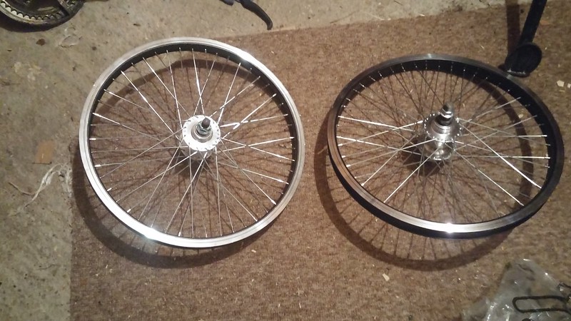 20150127_183729 20150127_183729 by duncancmartin, on Flickr Box section steel - 1.6mm wall, 40mm square. I got 6m, and I think it was about 40 quid! I ended up using a little under 3m, so I've got enough to make another if I want! I used a holesaw to cut the end of this one so that I can weld in the pivot for the rear triangle. Originally I actually just made a hole with steel at the end so it was extra sturdy, but when I put the pivot point in the hole I didn't have enough clearance at the back for the triangle to attach! So I binned that idea and just did it the way the plans said, relying on the welds to hold... 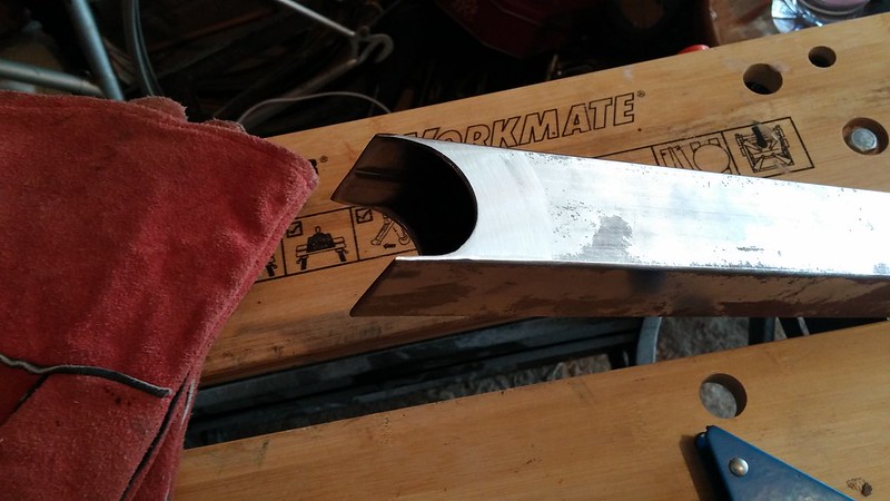 20150221_105332 20150221_105332 by duncancmartin, on Flickr Held in place so that it can be welded in properly... 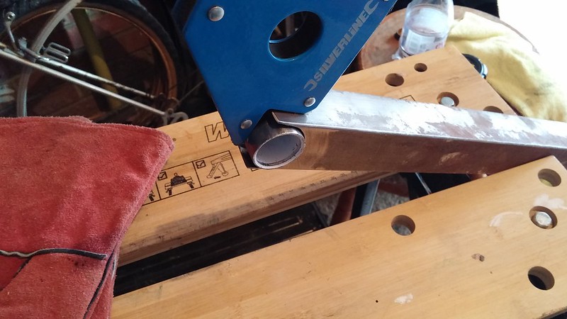 20150221_105420 20150221_105420 by duncancmartin, on Flickr Ugly (but sturdy) welding:  20150221_115344 20150221_115344 by duncancmartin, on Flickr 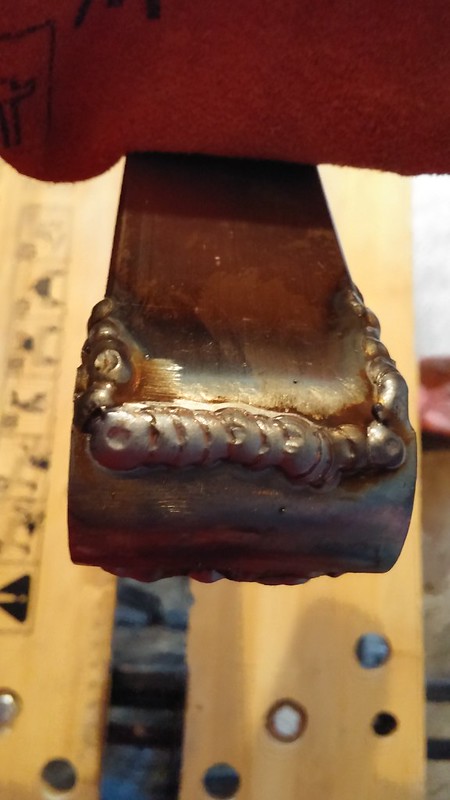 20150221_120606 20150221_120606 by duncancmartin, on Flickr Cleaned up a bit on the grinder: 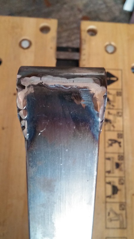 20150221_121715 20150221_121715 by duncancmartin, on Flickr Here's the suspension mounting plates that I chopped off the donor bike:  20150222_162303 20150222_162303 by duncancmartin, on Flickr Then they got welded on (after guessing exactly where they should go so that the seat back wouldn't foul he shock)  20150228_165219 20150228_165219 by duncancmartin, on Flickr And here's them and the pivot point in use. 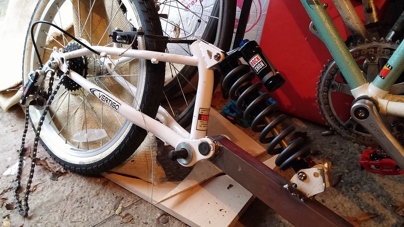 20150228_170658 20150228_170658 by duncancmartin, on Flickr This was all done by the end of February 2015, so that was actually reasonable progress so far. Then things slowed down a bit... |
| |
|
|
duncanmartin
Club Retro Rides Member
Out of retro ownership
Posts: 1,320
Club RR Member Number: 70
|
|
Aug 21, 2016 19:16:50 GMT
|
The next bit of the process is to create and attach the backrest: 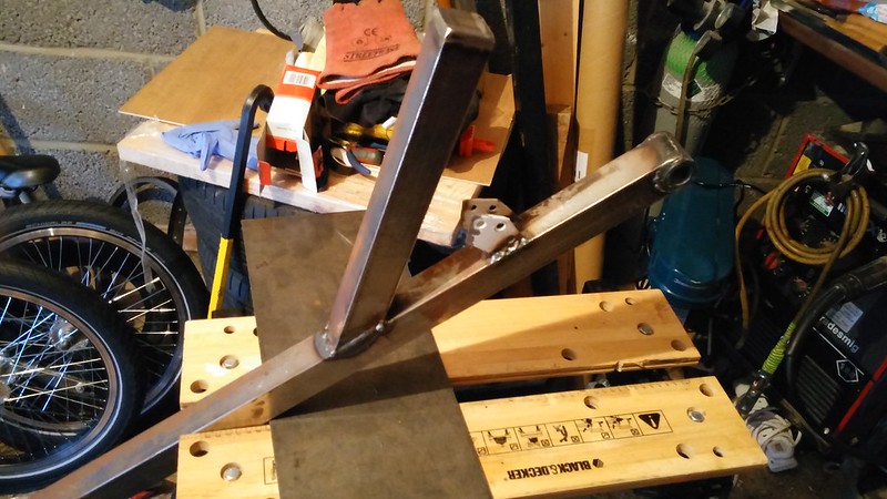 20150301_161152 20150301_161152 by duncancmartin, on Flickr At this point I realised that the threads on my wheels would be rotating in opposite directions, so if I attached a screw on brake disk mount to the right hand one it would unscrew whenever I tried to brake! After a little thought I figured I'd just bolt the screw on addapter to the hub, so I drilled these holes: 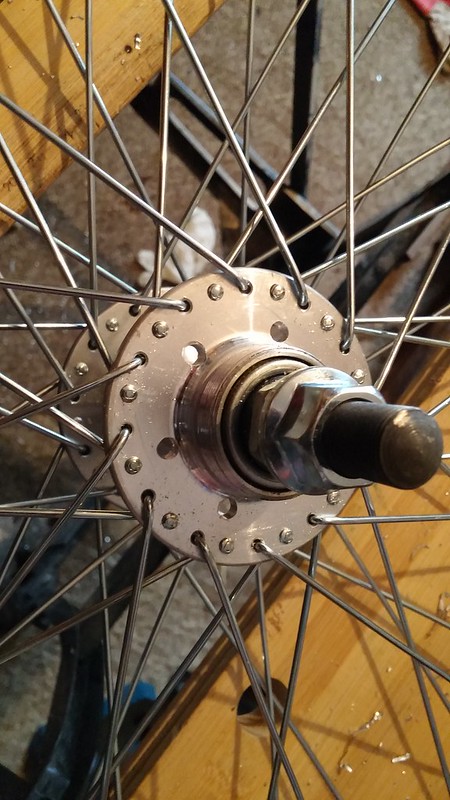 20150328_144304 20150328_144304 by duncancmartin, on Flickr And bolted the disk and screw on adapter through them: 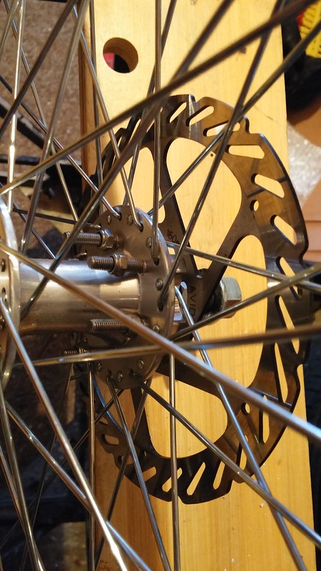 20150328_172102 20150328_172102 by duncancmartin, on Flickr I wasn't convinced that this would be effective, but it's been done on other AZ trikes, and apparently it works. There's some threadlock on the threads, and it's done up really tight, so this is more belt and braces than seriously stressed bolts, but we'll have to wait and see how well it stays put... I also got some 15mm (x 50m) bar, and then drilled 14mm holes for the axles to go through:  20150228_165118 20150228_165118 by duncancmartin, on Flickr Here's the practise go I had at welding the spare one onto a chopped remnant of the fork CROWN. This bit was quite tricky to get the angle good, and also it's a really stressed weld, between a 15mm bar and a pretty chunky bike part (the wall sizes were probably 5mm thick). I turned the welder up to power setting of 7 (out of 8), and bashed the hell out of the test piece. I managed to hold the bar in the vice and hit the fork CROWN so hard that I bent the 15mm thick bar (without breaking the weld)!  20150314_122412 20150314_122412 by duncancmartin, on Flickr More to come in a bit! Cheers Duncan |
| |
|
|
taurus
Posted a lot

Posts: 1,084
|
|
Aug 21, 2016 19:35:07 GMT
|
|
This is brilliant. Bookmarked.
|
| |
|
|
|
|
|
Aug 21, 2016 20:14:55 GMT
|
We've got an ICE Trike at work, very much like what you're building but with a hell of a lot more engineering gone into it, and obviously they cost a lot more ££££! We happen to be a dealer for them, and as we're an accessible cycling charity each one I've built this year has had an adaption or alteration to the spec of some kind, I'm just in the process of assembling my 2nd electric assist one but first crank driven system, no pics of that one yet but I do have some of one with a rear wheel drive system I built for a 9 year of hemiplegic lad that was fully left hand controlled. flic.kr/s/aHskzUWyNqlove the idea of building your own though, the ICE trikes are all folding, its a pivot much like any other folding bike placed at a 45 degree angle so the rear wheel folds up and around into the centre of the crucifix. |
| |
|
|
duncanmartin
Club Retro Rides Member
Out of retro ownership
Posts: 1,320
Club RR Member Number: 70
|
|
Aug 21, 2016 20:32:40 GMT
|
The ICE trikes are very nice, but they are serious money. If mine is half as good for an eighth of the money then I will be very happy! Dinner over, on with the story... After a couple of months break, I started on the cross boom. This is where those head-tubes you saw earlier ended up. I used the holesaw again to get the right camber and caster angles. Before chopping out the ends of the tube, it looked like this (note industrial MIG welder and curse word pillar drill in the background): 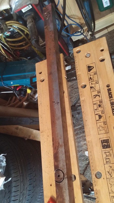 20150504_162902 20150504_162902 by duncancmartin, on Flickr With the headtube balanced in the right place it looked like this:  20150504_165356 20150504_165356 by duncancmartin, on Flickr And then finally welded up and cleaned up with the flap disk, it looked like this: 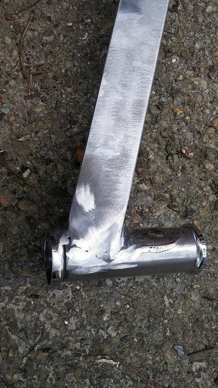 2015-09-27_04-00-53 2015-09-27_04-00-53 by duncancmartin, on Flickr At the point where I'd done this on both sides, I discovered something really irritating - when I had been welding the headtubes on I'd fired a couple of bits of welding wire straight through the gap, and now there was something rattling around inside the tube, and there was no hole to get it back out of! After much thought I drilled a small hole in the middle of the boom, and tried to magnet the rattly bits out. That failed dismally!  Eventually, I got some double sided tape and stuffed it through the hole - shook the tube up and down a lot, and managed to capture the loose bits on the tape! they even came out of the hole again afterwards! Then there was a big gap where I got sidetracked into other projects like constructing a set of replica Roman auxilliary shields (that's another thread entirely!). Eventually, I got back to this and realised I had to work out where the boom should live. I couldn't follow the plans, because they call for a v shaped boom, but I'd decided a straight one would be easier! (And also because I figured it would create more of a compact shape if folded.) So I mocked it up and experimented a bit: 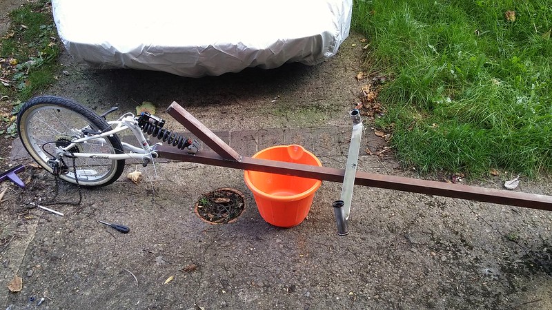 2015-09-27_04-01-26 2015-09-27_04-01-26 by duncancmartin, on Flickr When I'd finally decided it was good I tacked it and welded it in place. As you can see, my welding is getting better: 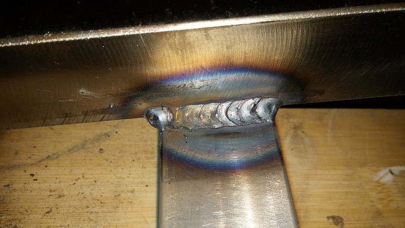 2015-10-11_06-38-00 2015-10-11_06-38-00 by duncancmartin, on Flickr I'm still not 100% sure the boom is in the right place, so I'm not going to add any extra re-enforcing gussets until I've ridden it and made sure the backs of my legs don't clobber it where it is! I added seat mounts next - that was relatively straightforward: 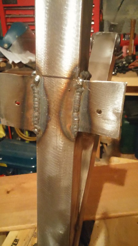 2015-10-10_08-13-47 2015-10-10_08-13-47 by duncancmartin, on Flickr and then ground the welds flat so that the seat base would sit properly: 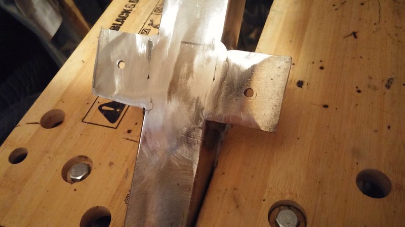 2015-10-11_06-37-08 2015-10-11_06-37-08 by duncancmartin, on Flickr Finally, with the frame in reasonable shape, I used a nylon clean and strip disk to remove all the surface rust, and brushed some grey primer on to stop it coming back (another unusual use for a toe-strap - I should add it to the list on that other thread!): 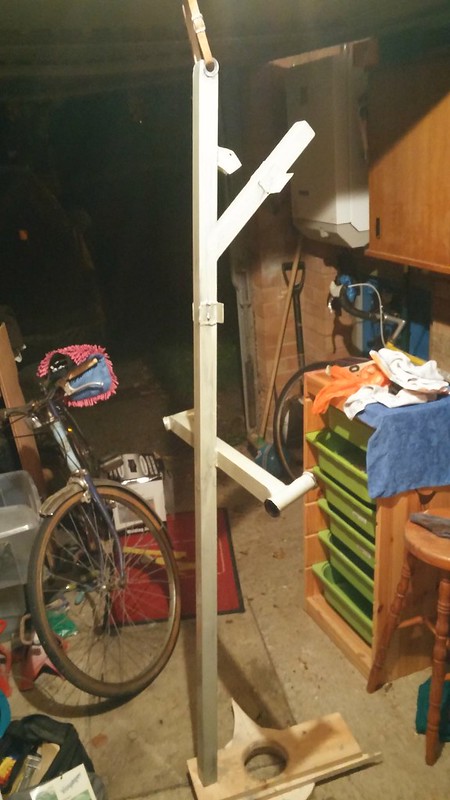 2015-10-11_09-27-48 2015-10-11_09-27-48 by duncancmartin, on Flickr That brings us up to the start of December 2015 - we've almost made it up to this year! Cheers Duncan |
| |
|
|
duncanmartin
Club Retro Rides Member
Out of retro ownership
Posts: 1,320
Club RR Member Number: 70
|
|
Aug 21, 2016 20:37:18 GMT
|
Drawing inspiration from the ICE trikes, and some other pictures I saw on the web, I got hold of a crappy folding bike FnF, and then I chopped it up for bits: 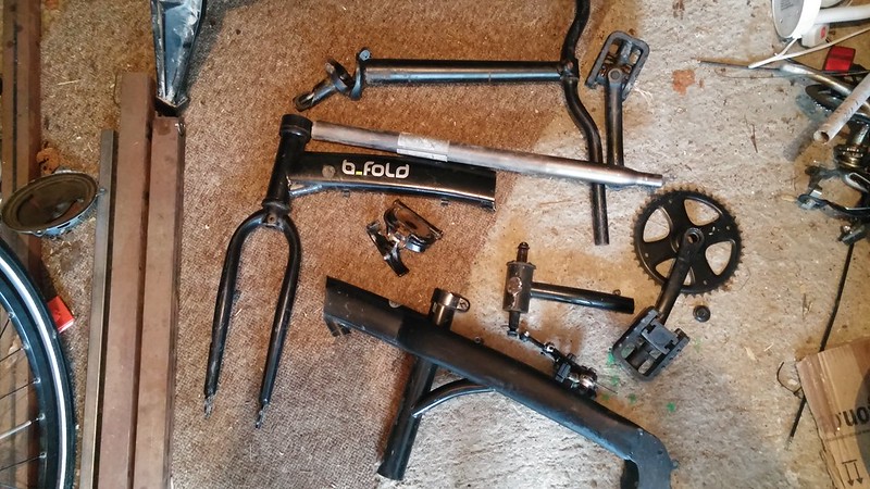 20150504_174943 20150504_174943 by duncancmartin, on Flickr I'm hoping that I can use the stem for the next project (swb recumbent), and I'm sure I can make something with the funky rear forks (20" wheel though) and the long seat tube. Gotta get my money's worth! I eventually got around to sticking the front wheels on, so it ended up on it's own wheels like so: 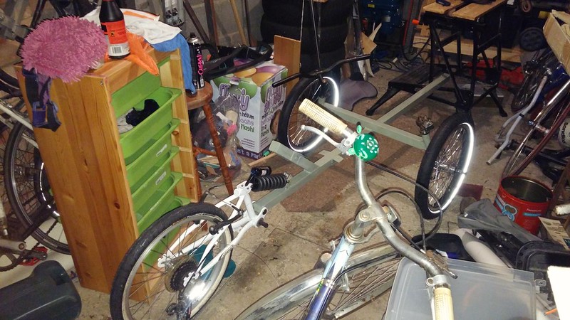 2015-10-23_08-56-30 2015-10-23_08-56-30 by duncancmartin, on Flickr  2015-10-23_08-56-46 2015-10-23_08-56-46 by duncancmartin, on Flickr I had some 3mm plywood hanging about, so I cut out a couple of pieces and bonded them together for the seats: 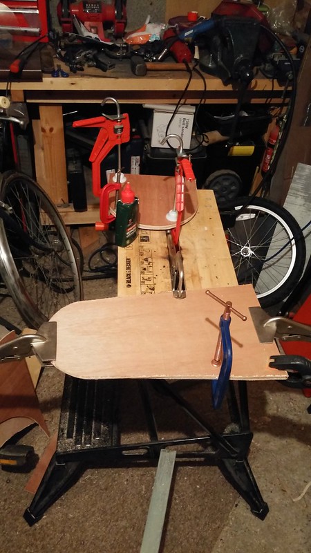 2015-11-01_05-07-27 2015-11-01_05-07-27 by duncancmartin, on Flickr Then I drilled holes and put T nuts in and screwed them to the frame to see how it would work. Followed by some CAD (cardboard aided design) to see how the fold would work if it folded over the top like an ICE trike. 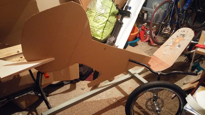 2015-12-11_09-51-37 2015-12-11_09-51-37 by duncancmartin, on Flickr I've since thought that I might fold the back wheel underneath instead, because that would put the joint in compression rather than tension. It would also mean that I could put the pivot point where the seat meets the backrest, which is probably the point that would cause the shortest overall package. HP Velotechnic fold that way, and their fold looks very easy to do. I need to do some more CAD to see how that would actually work! I got some foam from Hobbycraft and cut it to the right shape for the backrest and seat base: 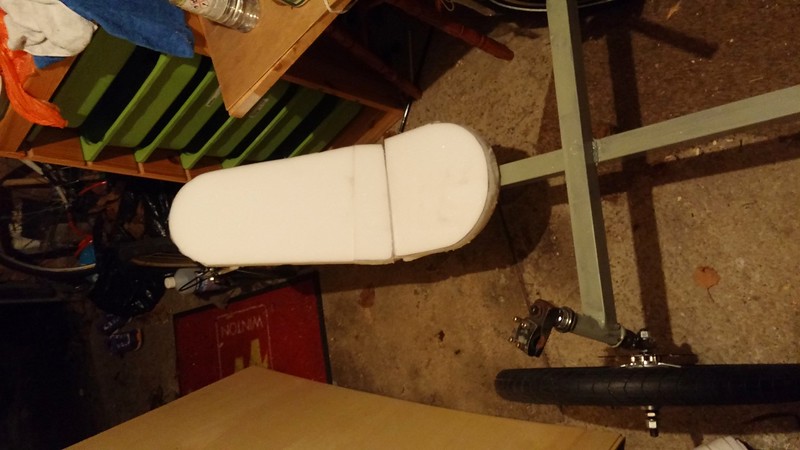 2015-12-04_10-09-17 2015-12-04_10-09-17 by duncancmartin, on Flickr And so I painted the bases: 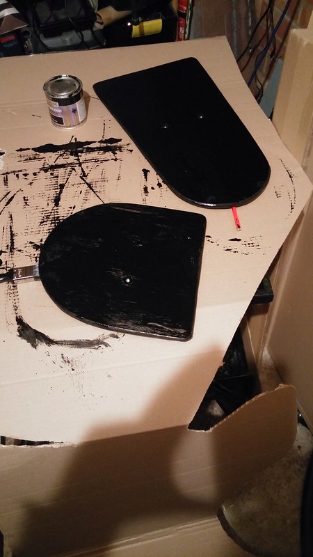 2015-12-12_05-55-08 2015-12-12_05-55-08 by duncancmartin, on Flickr Last weekend I strapped the rear triangle to the back of my fixie and took it to the Broken Spoke Workshop to replace the bottom bracket (with a really short one that came with a Truvativ crankset) 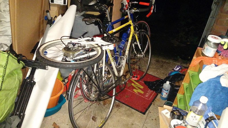 2015-12-13_07-41-16 2015-12-13_07-41-16 by duncancmartin, on Flickr I then chopped the arm off the crankset so it will work properly as a jackshaft. The plan is to run the middle ring to the freewheel, and then the front chainset to the inside ring of the jackshaft. Crankset mutilation: 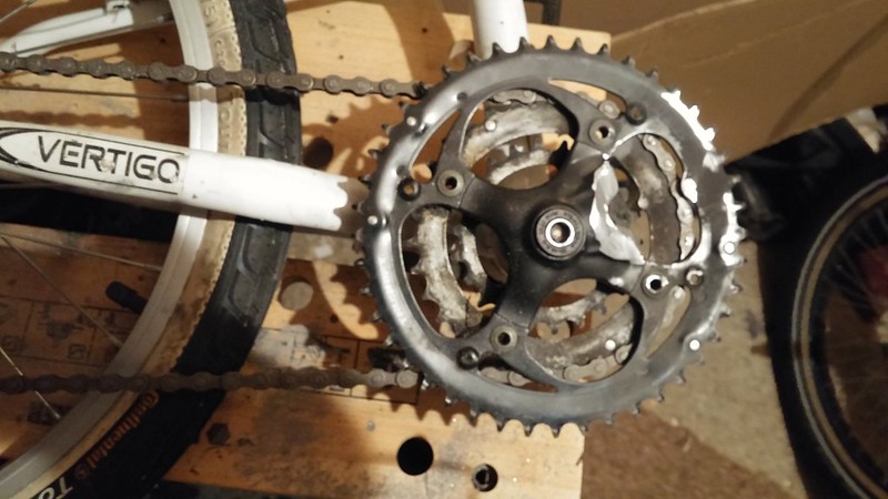 2015-12-18_10-07-27 2015-12-18_10-07-27 by duncancmartin, on Flickr 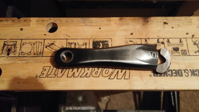 2015-12-18_10-07-38 2015-12-18_10-07-38 by duncancmartin, on Flickr Then I put the triangle back onto the bike, so that the rear end is essentially finished. After that, I stapled some vinyl over the seat foam - it's quite good on the top but pretty scraggly on the bottom. I figure I'll sort the bottom out once I've actually tried riding on it and I'm happy with how comfortable it is: 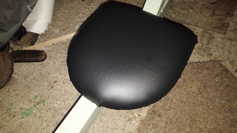 2015-12-18_10-07-52 2015-12-18_10-07-52 by duncancmartin, on Flickr And finally, I made the clamp bits to attach the front bottom bracket to the main boom (it moves along the boom to adjust for leg length).  2015-12-19_04-59-17 2015-12-19_04-59-17 by duncancmartin, on Flickr Became this:  2015-12-19_04-59-41 2015-12-19_04-59-41 by duncancmartin, on Flickr Became this:  2015-12-19_04-59-53 2015-12-19_04-59-53 by duncancmartin, on Flickr Now I need to weld the plates to the BB shell either side of the main beam and put bolts through to allow it to be clamped. I'm really frustrated that the bottom bracket I ordered hasn't turned up despite getting an email from Royal Mail saying that it had been delivered!  But I want to chase the threads in the BB shell before I install the bottom bracket properly (after I've done the welding), so I'll have to wait until the Broken Spoke is open again (I don't have my own BB thread tool). The remaining really difficult bit is welding on the brake/steering arms. They are supposed to be parallel to the ground, and to the brake disks. I've been putting that off, but there isn't much else left on the critical path to riding it! Cheers Duncan I'll post some more updates tomorrow... |
| |
|
|
|
|
|
Aug 21, 2016 20:38:04 GMT
|
|
Maybe a tip...if your not sure where you want something just tack it a few time to do the job you want . Then its a hell of a lot easier to remove ..
|
| |
|
|
duncanmartin
Club Retro Rides Member
Out of retro ownership
Posts: 1,320
Club RR Member Number: 70
|
|
Aug 21, 2016 20:43:57 GMT
|
Maybe a tip...if your not sure where you want something just tack it a few time to do the job you want . Then its a hell of a lot easier to remove .. I do that with most things, but the cross piece is on top of the main beam, and if the weld breaks I'll be smacked in the  with a bit bit of metal and be shifting down the street with no brakes or steering! So I figured discretion was the better part of valour, measured a couple of times and then welded it properly! Cheers Duncan |
| |
|
|
|
|
|
Aug 21, 2016 21:53:15 GMT
|
|
I built my own along these lines but being too tight to buy the plans made it up as i went along. Looks good though. I suppose I should do a build thread but I have absolutely no idea how to do it.....
|
| |
|
|
|
|
|
|
|
Aug 21, 2016 22:02:52 GMT
|
how many likes will it take for a new thread zoompod ?  |
| |
|
|
|
|
|
Aug 22, 2016 12:30:43 GMT
|
I built a 2 wheel a few years ago, best bit of advice I wish I'd had, make the seat as strong as you can and fit outriggers to support the sides, you'll be pushing very very hard against it. crossmember location, just behind you knee when fully extended (slight bend in knee). if you can, put a bend in the front tube to raise the cranks, else you'll have to shorten you stroke (and waste power) to be able to pedal it without hitting the crossbeam. . bottom bracket, use an american BB shell (old bmx) and an adapter to english bb, no fixed threads and no worry about welding the tube and trashing it. bit more surface area on the weld too, for extra rigidity, which you'll find is really important when you start cranking on it. looking good so far, will be keeping an eye on this, I want to build a trike at some point, if only my garage was big enough. wont detract from your thread with pics of mine. |
| |
|
|
|
|
|
Aug 22, 2016 12:42:28 GMT
|
|
I'll have to work out how to post pictures first..... I have about 80 pictures detailing the whole build, I think it would be pretty self explanatory if anyone wanted to copy it.
|
| |
|
|
duncanmartin
Club Retro Rides Member
Out of retro ownership
Posts: 1,320
Club RR Member Number: 70
|
|
Aug 24, 2016 20:44:33 GMT
|
I added the bracing for the bottom bracket next. The plates I had cut previously were too short, so I had to make some more. 40mm holesaw, angle grinder with a cutting disk and some 4mm sheet created this: 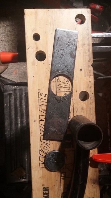 2016-01-02_01-57-08 2016-01-02_01-57-08 by duncancmartin, on Flickr I lined everything up thus: 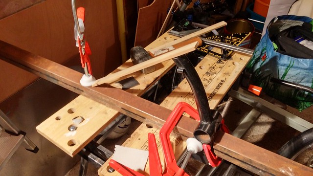 2016-01-02_06-13-43 2016-01-02_06-13-43 by duncancmartin, on Flickr and welded the plates onto the BB shell.  2016-01-02_06-14-02 2016-01-02_06-14-02 by duncancmartin, on Flickr The welds were crappy and blobby because I forgot to clean the paint off the shell before tacking the plates on, but the joins seem pretty sturdy. Maybe a little too sturdy - the cardboard I used to space my joint for welding clearly wasn't correctly placed and the front edge is a bit on the tight side! Still, nothing a bit of brute force and ignorance can't fix. I cleaned the welds p a bit, so it all looks a bit better now: 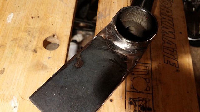 2016-01-02_07-47-22 2016-01-02_07-47-22 by duncancmartin, on Flickr 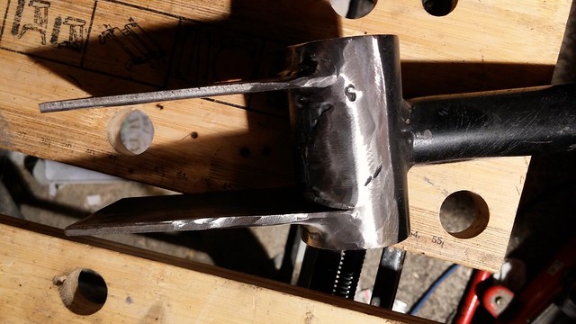 2016-01-02_07-47-10 2016-01-02_07-47-10 by duncancmartin, on Flickr All that remains is to mark it up and drill some holes for the bolts that go under the main boom. Oh, and recut the BB threads, so the BB can be trial fitted... That would leave me with just the pulleys and tensioning to fix to have all my propulsion bits sorted - I really should get on with the steering/brake arms soon! Cheers Duncan |
| |
|
|
duncanmartin
Club Retro Rides Member
Out of retro ownership
Posts: 1,320
Club RR Member Number: 70
|
|
Aug 24, 2016 20:45:32 GMT
|
The next piece of progress... I cut and drilled some brake caliper mounts (2mm steel), some steering tabs (4mm steel - took forever to drill the holes!) and also drilled the holes in the bottom bracket assembly. This is what all those bits actually look like: 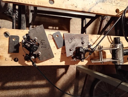 2016-07-29_06-32-41 2016-07-29_06-32-41 by duncancmartin, on Flickr Hopefully tomorrow I can weld them on - once that's done I'll only need to sort out the tie rod (and I've got the bits) before I can had an unpowered roll down the hill! ;D Cheers Duncan |
| |
|
|
duncanmartin
Club Retro Rides Member
Out of retro ownership
Posts: 1,320
Club RR Member Number: 70
|
|
Aug 24, 2016 20:46:47 GMT
|
And the last update for tonight... I had originally cut out the brake supports according to my cardboard templates, but when I came to actually attach them with the brakes attached, I realised I had to modify them a bit! Still, I eventually fettled them until they fitted well enough and then I welded them up. I then realised that the steering tab wouldn't fit in the right place on the right hand one, so I had to cut some extra out of the brake mount (not a problem - it was just a quarter of an inch on the end). After that, I measured it twice, and welded on the steering tabs. 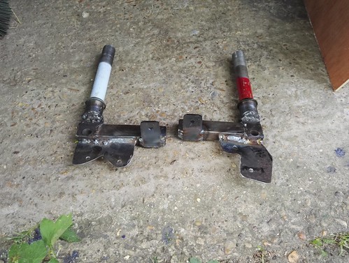 IMG_20160730_174924 IMG_20160730_174924 by duncancmartin, on Flickr The welding isn't quite as pretty as you would like (though some of it's not too bad), but it's strong enough: 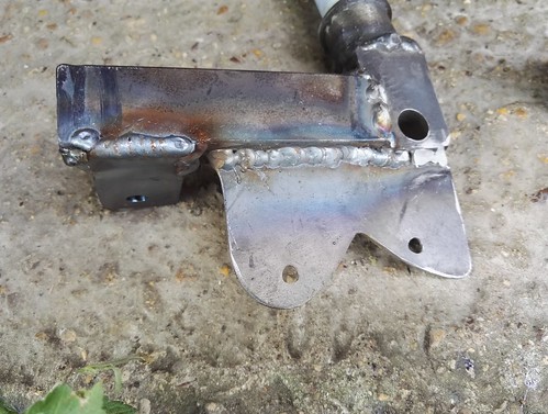 IMG_20160730_174939 IMG_20160730_174939 by duncancmartin, on Flickr 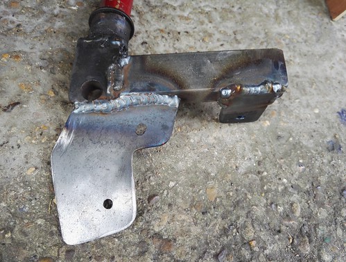 IMG_20160730_174950 IMG_20160730_174950 by duncancmartin, on Flickr Once I've made dinner (and these things have cooled down), I'm going to put these back into the frame and try to work out how long the tie bar needs to be - then I can weld on the bolts for the track rod ends. At which point, adding the wheels, the brakes, and the handlebars (oh yeah, and the seat back) will allow me to try a roll down test. Cheers Duncan |
| |
|
|
|
|
|
Aug 25, 2016 12:54:07 GMT
|
|
This is great! Have been reading through the AtomicZombie website, now I can weld I'm definitely going to be making some of those designs- the Spincycle has put a big grin on my face so I think that will get made first. On our local facebook page people are often trying to get rid of bikes for very cheap, might have to start stockpiling ...
|
| |
|
|
duncanmartin
Club Retro Rides Member
Out of retro ownership
Posts: 1,320
Club RR Member Number: 70
|
|
Aug 25, 2016 18:33:28 GMT
|
This is great! Have been reading through the AtomicZombie website, now I can weld I'm definitely going to be making some of those designs- the Spincycle has put a big grin on my face so I think that will get made first. On our local facebook page people are often trying to get rid of bikes for very cheap, might have to start stockpiling ... Keep an eye on freecycle (or your local equivalent) - people give away loads of broken bikes you can chop up. And also unloved local stuff on eBay - I got a frame for chopping up for 99p the other day. Cheers Duncan |
| |
|
|
duncanmartin
Club Retro Rides Member
Out of retro ownership
Posts: 1,320
Club RR Member Number: 70
|
|
Aug 26, 2016 14:46:08 GMT
|
I've not managed to have my first ride (roll) on it yet. However, I have made some real progress - the steering link bar is all welded up (including adding a squared off part in the middle that I can turn using a 13mm spanner to open/close it) and installed... Plus the cranks and pedals are on. Welding the nuts on the end of the steering rod is really helped by the groove in the workmate: 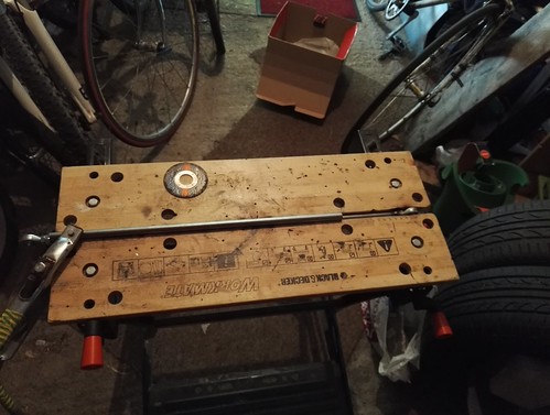 IMG_20160731_152429 IMG_20160731_152429 by duncancmartin, on Flickr I think she needs to grow a bit: 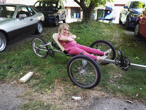 IMG_20160731_171159 IMG_20160731_171159 by duncancmartin, on Flickr Waiting in the garage for the next session: 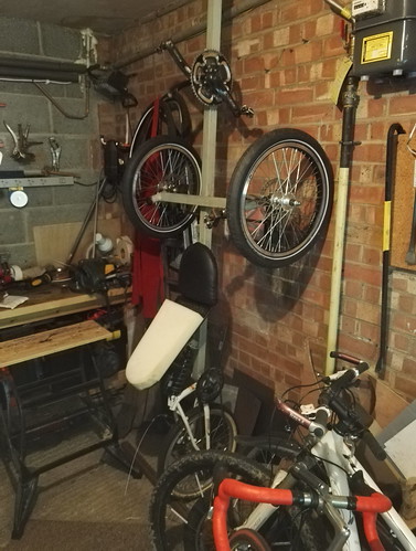 IMG_20160731_173009 IMG_20160731_173009 by duncancmartin, on Flickr Now for the downside - the reason I didn't get to ride it is because I couldn't fit the brakes. Sure, I could slot the brakes over the disks and then bolt them on, but when I did that, the wheels wouldn't go round properly! Aside from needing shorter bolts (they hit the disks if I do them up fully), the alignment isn't quite there and the calipers rub on the edge of the disks. I'll get some washers with the bolts, and I'll have to make the brake holes into slots. Once that's done, I should be able to roll. The next steps are to get some chain (I reckon I need 3.45m or thereabouts), a (cheap) derailleur to put some tension into the return side, a chain tube, and a round groove pulley (so I can route the tensioned side). Oh, and some brake and gear cable for the rear mech/brake. I think that's all the pars I need to make it actually usable, and fitting them is mostly a matter of regular bike mechanics rather than complex recumbent engineering! Cheers Duncan |
| |
|
|
duncanmartin
Club Retro Rides Member
Out of retro ownership
Posts: 1,320
Club RR Member Number: 70
|
|
Aug 26, 2016 14:46:52 GMT
|
As often with this build, 2 steps forward and some head scratching! I got some chain and hosepipe last week, and the pulleys arrived in the post. Today I got some bolts, so I was in a position do get on with the trike again. I have finally got my brakes into a reasonable position. They both have a little intermittent rub, but I'm blaming that on the disks not being 100% round! It'll be annoying if it stays like that, but for getting it on the road and testing it, I'll put up with it! 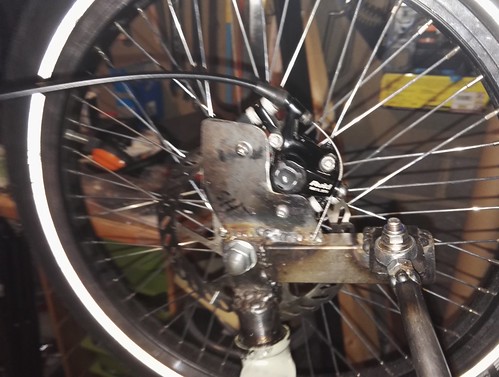 IMG_20160813_203928 IMG_20160813_203928 by duncancmartin, on Flickr I also installed the pulley. I got some M10 bolts with shoulders on, and then I realised that I needed to space the pulley off the main boom. I cut down a piece of the 12mm tube I used for the steering rod and put it over the bolt as a sleeve. Then I worked out where it needed to go, and I welded it on. 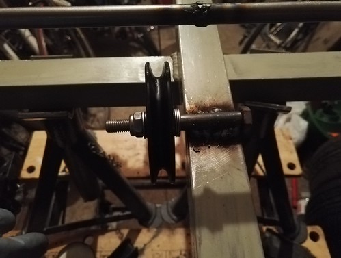 IMG_20160813_203945 IMG_20160813_203945 by duncancmartin, on Flickr Then I was trying to work out how much chain I needed (I got 3, and I need to use about 2.5, but it's how many links the .5 is that needs thinking), and I realised I had a problem. Because I'm using a jackshaft I need to add a tensioner for the return chain section, and I figured I would use a rear mech I have lying around. Because of how it works, I need to add a mount about an inch away from the beam - I figured adding some extra box section to the side would make it straightforward. But if I do that, then the box is in the way of the top (drive) section of the chain. The way that I was thinking of mounting the rear mech: 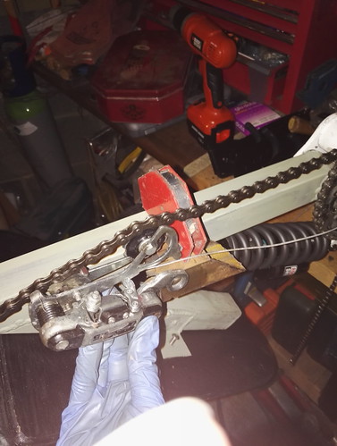 IMG_20160813_204859 IMG_20160813_204859 by duncancmartin, on Flickr The problem with the drive section of the chain: 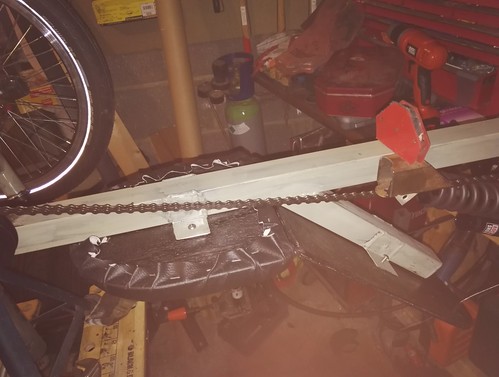 IMG_20160813_205205 IMG_20160813_205205 by duncancmartin, on Flickr I could make the box bigger (or offset it somehow) and run the drive part of the chain through the box. I'm not sure if that would be a good solution though, time for some thinking! Cheers Duncan |
| |
|
|
|
|


 I'll try to answer any questions without infringing on the instructions I used (if you want to do it, just buy a set of plans, they are super detailed and super cheap!)!


 Eventually, I got some double sided tape and stuffed it through the hole - shook the tube up and down a lot, and managed to capture the loose bits on the tape! they even came out of the hole again afterwards!
  But I want to chase the threads in the BB shell before I install the bottom bracket properly (after I've done the welding), so I'll have to wait until the Broken Spoke is open again (I don't have my own BB thread tool).

