|
|
|
|
|
In that last pic you can see the old shift lever. It worked great with a Fiat 500 and Fiat 600 gearbox, but for the Hewland it needed to be redesigned. It was based on a steering U-joint, and they are perfect for this. They are cheap ( you can find a box full of them at swapmeets for a fraction of the cost of 1 heim joint ), overbuilt, and last long without any slop or play.  A Hewland has the shiftrod in the perfect place for a mid engined application. Its at the lower right hand side, so that gives a nice straight route past the engine and driver to a spot next to the steering wheel, on the RHS. I had to flip my gearbox ( and flip the diff to keep 4 forward gears  ), to miss the alternator and starter on the Bike engine. The only other way would have been to have a bellhousing that was about 6" deeper, which would have added that length to the wheelbase. And that was not acceptable. So with the gearbox upside down ( this shouldnt be a problem, since Hewlanf flipped a VW box upside down to make the MK9, I'm just putting it back to the VW configuration ), the shiftrod was now at the top left. Where it would run into the rear suspension, then the LHS inboard rear brake, then the cylinder head, and then the seat and me. I could try to snake it between the box and the suspension, over to the right, and then straighten it back out again. But that was going to be super tight, hard to adjust and work on. So I decided to go to the back, through a seesaw bracket ( not built yet ), to miss all the parts and go forward past the engine on the RHS. That meant I had to reverse the front-back action, but keep the left-right action as is. Since the seesaw isn't built yet, I can use that to get my ratios right ( the feel and force required is really important, it needs to be precise and direct, but not so heavy it hurts your arm with a day's worth of racing ). And I could build the shifter pretty much just to fit the space and ergonomics. |
| |
|
|
|
|
|
|
|
|
|
Some of the parts I started with.  And some left over Burton 4link.  Square bar.  Drilled and tapped for the 1/2" fine thread bolt.  Which will hold the 1/2" Heim joint.  |
| |
|
|
|
|
|
|
|
 I took the steering U-joint apart.  I cut , drilled, and shaped the piece of square bar. And cut the middle piece out of a Yamaha bike headbolt that was shanked down to 10mm. Which was a good fit on the steering U-joint needle bearings.  Pressed in place.  Test fit.  |
| |
|
|
|
|
|
|
|
|
|
Just a mockup , at this point...  I took some more U-joints apart to get the right combination of parts. A splined piece that I pressed into a hollow piece of round bar, which will slide in a aftermarketr steering column mount ( sold for Buggies and Sandrails, I believe )  The LHS of the U-joint will still need to be swapped for a weld in version, which will be welded to the rod that mounts next to the engine. The slider will be welded to the rod in the drivers compartment. The splines are so it can be taken apart at what will be the rear firewall.   Hopefully more after next weekend... |
| |
|
|
|
|
|
|
|
|
Extraordinarily impressive!
John
|
| |
|
|
|
|
|
Jul 29, 2020 10:02:02 GMT
|
Thank you. |
| |
|
|
|
|
|
|
|
I got a little more done on the shifting mechanism. The shift rod coming out of the tranny is 9/16" round, with a 1/2" square part at the end of it. I was thinking about how I was going to machine that. The best I could come up with, with the tools I have, was to start with a piece of round stock. Drill it to 1/2 and 9/16", saw it in two lengthwise, and open up the 1/2" part with a 1/2" mill to get half of my square, and weld the 2 halfs back together. But then I realized that a 14mm 1/2" socket was already almost there...  There must be good reasons not to drill saw and weld Chrome Vanadium, but I decided to ignore those. The square part is a perfect fit between the rod and the socket, and after drilling it out to 9/16", the other side was too.   |
| |
|
|
stealthstylz
Club Retro Rides Member
Posts: 14,842
Club RR Member Number: 174
|
|
|
|
|
Ace. I think the gear change is the most overlooked bit of a lot of home builds (and OEM tbf). Seen some hilariously bad efforts on mid/rear engined home built stuff.
|
| |
|
|
|
|
|
|
|
The outside dia was a hair over 7/8", so I took it down to that so I could put on a 7/8" collar ( threaded side welded on, and square part of the socket split to give it good clamping force ) I took a piece of Double D steering shaft and heated and bent a 45deg. bend in it. And welded that to the socket & collar ( being very careful to keep it parallel to the shifting rod).  On the other side I bent it back down again, and I took more steering U-Joints apart to get one that I weld to the double D shaft. Again being careful to get the U-Joint exactly inline with the shift rod on the other side. I kept a bit of space between the down bend and the rear cover, so it can be removed without taking the double D shaft off the shift rod ( when all of the rear suspension is in, there is no clearance to do that ) Took a rear wheel off to check for clearance at full droop.  Because between the clearance to the DeDion tube at full droop, and the half shaft at full bump, and the shaft where it goes through the firewall, determines the height of the RHS shaft at its rear edge.   |
| |
|
|
|
|
|
|
|
|
|
The other side of the U-Joint on the LHS.  A weld in bung for the RHS.  RHS shortened and the bung welded in. A 3/16" strip with two 3/8" holes, 16" apart to connect the two sides ( this is just a temporary thing, it is only to get the ratio of the seesaw correct. It will be replaced with a better one later )  |
| |
|
|
|
|
|
|
|
I made a temporary center mount for the seesaw, and drilled a 1/4" hole through it and the seesaw as a first trial for the ratio ( determined by where the center pivot of the seesaw )  Several trials later I found the center. ( in this pic you can see two Heim Joints clamped to the mount, more about that later ) Part of trying to find the center for the seesaw meant changing the shifter. After mounting the shifter and trying it out while trying to find the center pivot for the seesaw, I found that for the amount of front to rear stroke with the weight & precision of the H pattern I wanted the big Heim in the shifter ran out of angle. Fortunately I had made a little extender to change the shifter when this car was still Fiat powered, with a nice old Abarth shiftknob. With those fitted to this shifter ( I cut it for for M10, like the old one, for just such an occasion ), the ratio was right, with enough travel. The Abarth shift knob feels more comfortable to the hand as well.  Now about those two Heims... Turns out, the rod where it comes out of the tranny, has a pretty loose fit. That translates to some slop on the far end ( rear ) of the double D shaft. That with the U-Joint on that side allows for some sideways movement at the center of that U-Joint. I could rebush the gearbox case, or I could leave it as is and take the LHS U-joint out. Advantages of that are weight, and eliminate the slop, and I can shorten everything by the length of that U-Joint ( 2.5" ) The angle movement of the seesaw is so slight while running it through its gears, and long enough from the center pivot to the LHS Heim, it would need very little sideways movement anyway. So that will work without binding... ( simplify and add lightness... ) I knew that all of this would take some time, and take a couple trials to get right, but I think I've got a pretty good idea of where I'm headed with it. Hopefully more after next weekend... |
| |
|
|
|
|
|
|
|
Ace. I think the gear change is the most overlooked bit of a lot of home builds (and OEM tbf). Seen some hilariously bad efforts on mid/rear engined home built stuff. I agree. I've seen some strange and/ or worn out sloppy shifters too. Seems to me taking some extra time to try and get it better, is worth it. When you get in a car and anything grabs your attention ( as a potential problem or annoyance ), its not right. That goes for brake / clutch & throttle pedals, steering, etc too... |
| |
|
|
|
|
|
|
|
Last pic didn't post.  |
| |
|
|
|
|
|
|
|
Left hand side U-joint cut off the double D shaft, and a new flange made for the Heim Joint. I still have to find the exact center and drill & tap it. Made a test piece out of 16Ga sheet, and put a bead in it with my Pullmax. Not happy with the bead, so I corrected the clearances of the bit that goes in the Pullmax ( by grinding on it )  I made a jig out of a piece of aluminum by transferring the holes from the temporary seesaw. And I made 2 new ( top & bottom ) 16Ga pieces, with improved Pullmax tooling the beads were a lot better. I made some spacers for the Heim Joints, and some pieces for what will be the center pivot of the seesaw.  Connecting the 2 16Ga pieces are 4 pieces ( front, rear, and 2 ends ) of 22Ga sheet. 3/4" tall, with a 1/8" flange along each side. And welded them together in the jig. 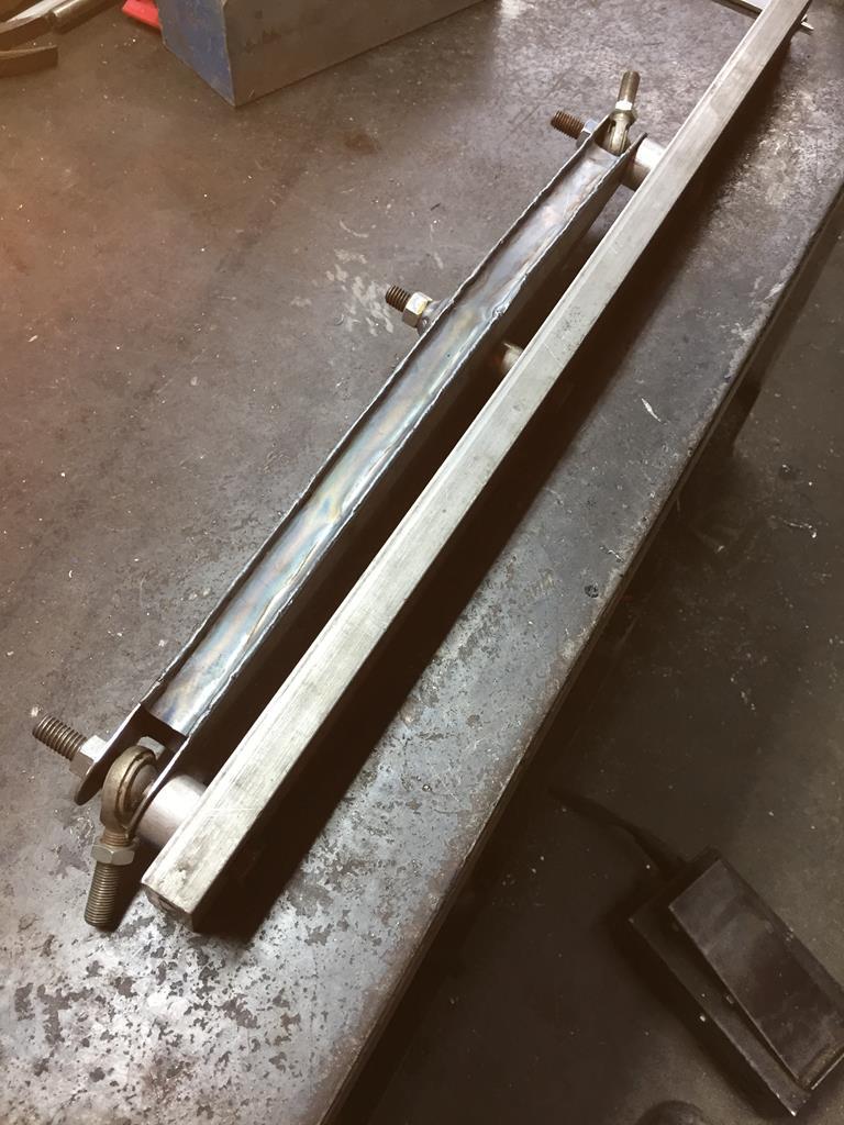  The end result is very rigid, should be more than strong enough, and is really light... |
| |
|
|
|
|
|
Aug 11, 2020 20:53:18 GMT
|
|
Right now I'm back to taking lots of measurements.
I had already planned to put a stiffener in the enginebay, but because there is so little space I had to wait with that to see where exactly the shifting mechanism was going to end up.
In this spot, I'll have to find space for the seesaw center pivot point and 2 suspension pickup points mounting points for the tunnel, rear bodywork, rear wing, exhaust, and a center mounting spot for the engine/gearbox.
The seesaw center point and suspension pickup points have to be in the exact right spot to work right, but I can move the others around a bit if I have to.
I think I have a plan for that now, but to get all the clearances right I have to make the halfshafts first.
Then I can make the stiffner, and then mount the seesaw & suspension, and then the rest...
|
| |
|
|
|
|
|
Aug 11, 2020 21:07:34 GMT
|
|
Up to this point, I wasn't sure if the stiffner was going to be bolt in, or weld in.
Bolt in is heavier and not as rigid, but if it is in the way of the engine/gearbox coming out that's the way it has to be.
I don't have space for any triangulation in the lower horizontal part of the stiffner, but I think I have a plan.
Looks like I can make something that is basically a Lotus 23 bulkhead stiffner laid flat, with all the vertical triangulation welded off that into the rear of the chassis.
The engine/gearbox can then drop straight down, if they have to come out...
|
| |
|
|
|
|
|
|
|
To find the correct shape of the stiffner, I made a test piece out of plywood. That gave me an idea of the clearances I could get in the space available, where the tubes would weld on to it for triangulation, etc. The stiffner will be at the same 8 deg angle as the tunnel, so I was able to check that for clearance too. This is with the rear suspension at full droop.  This is the plywood test piece screwed to a couple of 2X4's for stiffnes.  |
| |
|
|
|
|
|
|
|
I made a dimple die.  And tried that out on a piece of 22Ga sheet, after I cut a 2" hole in it with a holesaw.  I cut a scrap piece of thinwall 3/4" square tubing lengthwise, So I could figure out the best way to bend that ( on the inside and the outside corner ).  So then I could cut a 10' piece of thinwall 3/4" square tube lenthwise, and do the same...  |
| |
|
|
|
|
|
|


 ), to miss the alternator and starter on the Bike engine.


