jonomisfit
Club Retro Rides Member
Posts: 1,787
Club RR Member Number: 49
|
|
May 27, 2020 20:02:02 GMT
|
I did a little bit tonight. Started on the other skirt. What was instantly apparent when putting the skirt on. I'd mucked up a measurement when I repaired a bit of the sill and had the body kit clip hole in the wrong place,  P1030735 P1030735 by jono_misfit, on Flickr drill  P1030736 P1030736 by jono_misfit, on Flickr filed to shape  P1030737 P1030737 by jono_misfit, on Flickr skirt on  P1030738 P1030738 by jono_misfit, on Flickr this shows how far out it was  P1030739 P1030739 by jono_misfit, on Flickr I may weld it up, or I may just drop in a spare clip to fill the hole all bolted on  P1030740 P1030740 by jono_misfit, on Flickr this needs a slight fettle back 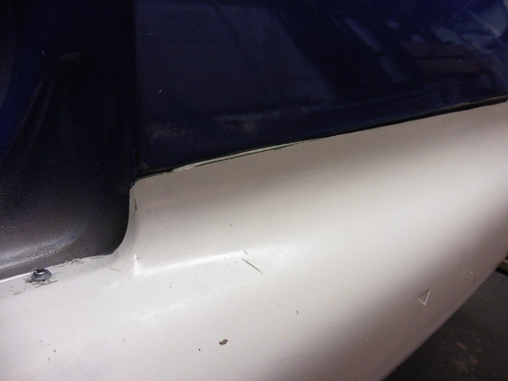 P1030741 P1030741 by jono_misfit, on Flickr  P1030743 P1030743 by jono_misfit, on Flickr in general this side isnt quite as good a fit as the drivers side, but its much better than some ive seen.  P1030744 P1030744 by jono_misfit, on Flickr  P1030745 P1030745 by jono_misfit, on Flickr this top edge could do with something to stop it pulling. The original skirts have another of the funny plastic clips here.  P1030743 P1030743 by jono_misfit, on Flickr However i think I can just bond on a 6mm stud fixing onto the skirt and put a nut on from the inside to pull it in.  P1030746 P1030746 by jono_misfit, on Flickr you can see the nylon fixing point bottom left on this pic. |
| |
|
|
|
|
jonomisfit
Club Retro Rides Member
Posts: 1,787
Club RR Member Number: 49
|
|
May 29, 2020 19:27:09 GMT
|
I got some suitable headlights off ebay and tried them out  P1030747 P1030747 by jono_misfit, on Flickr These were on for cheap, so I was suspicious but they look like they will do the job, and I cant see rust in them. need a really good polish though  P1030748 P1030748 by jono_misfit, on Flickr 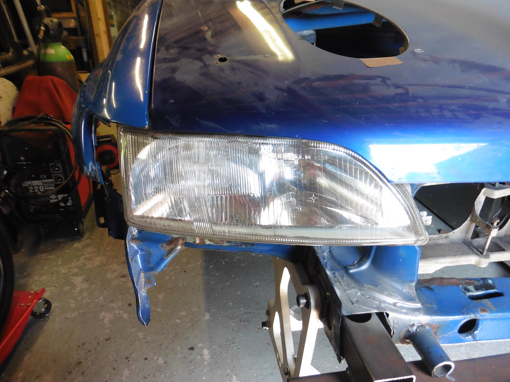 P1030749 P1030749 by jono_misfit, on Flickr theres still some bonnet / wing adjustment needed  P1030750 P1030750 by jono_misfit, on Flickr  P1030751 P1030751 by jono_misfit, on Flickr then started on the bonnet pins cut out the standard spiral for the bonnet adjuster  P1030752 P1030752 by jono_misfit, on Flickr  P1030753 P1030753 by jono_misfit, on Flickr cut some steel  P1030754 P1030754 by jono_misfit, on Flickr put in position  P1030755 P1030755 by jono_misfit, on Flickr set up a reference bar  P1030757 P1030757 by jono_misfit, on Flickr marked a line  P1030756 P1030756 by jono_misfit, on Flickr drilled some slightly odd shapped slots  P1030758 P1030758 by jono_misfit, on Flickr tacked the plates in, and tried out the bonnet pins, adjusted a bit more  P1030759 P1030759 by jono_misfit, on Flickr  P1030760 P1030760 by jono_misfit, on Flickr I had to extend the slots, so there is a load of fwd/aft adjustment on them 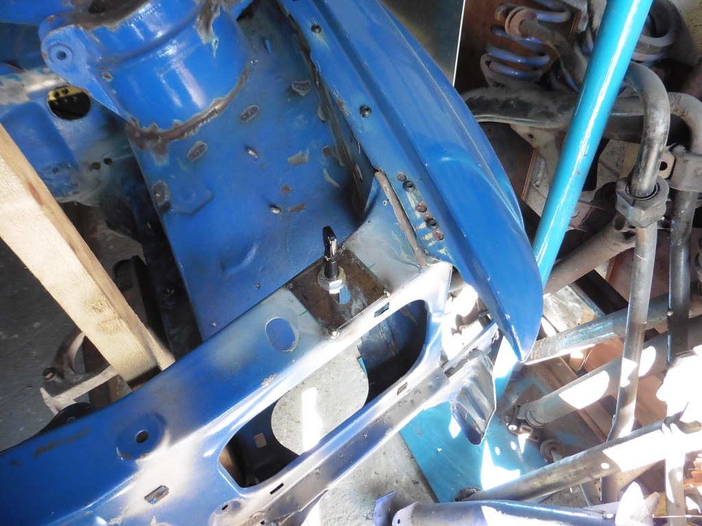 P1030761 P1030761 by jono_misfit, on Flickr 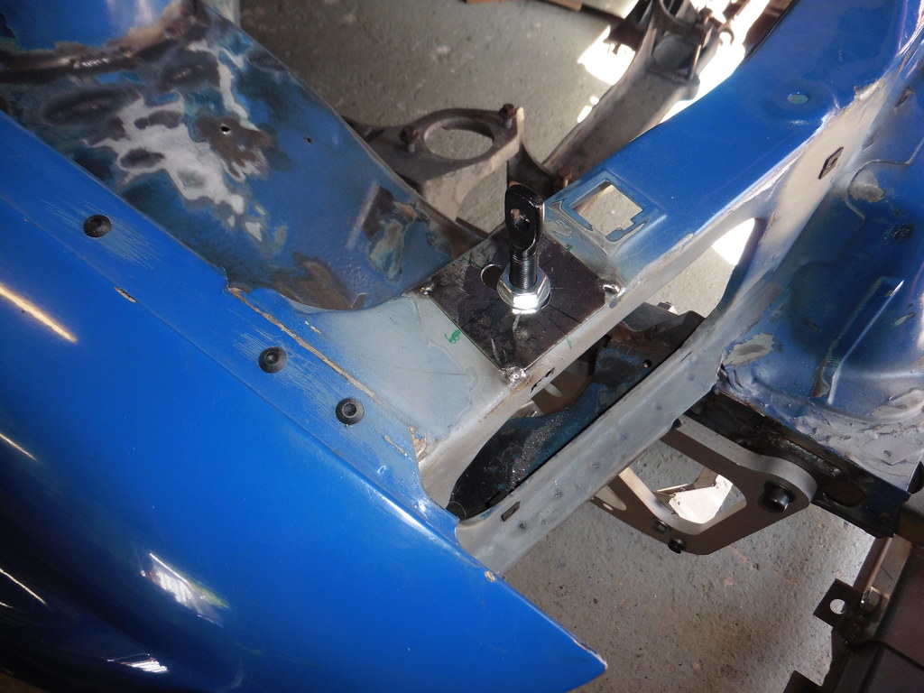 P1030762 P1030762 by jono_misfit, on Flickr hold the phone... they arent the same distance fwd/aft both side. Has the front been pushed back in a crash.... well yes... but not that much Is the bonnet badly adjusted... well yes...... but not that much Whats the problem then? the bonnet I have is off a rally car, so already has holes in it for bonnet pins. the passenger side has been drilled in teh wrong place..  P1030763 P1030763 by jono_misfit, on Flickr As shown by the previous butchery to the bonnet in the name of getting it in. I could weld it up and re-set it. But as the bonnet is already damamged and I have a brand new one there to convert I think i'll leave for the moment. As i'm now happy I've not fitted the plates in the wrong place i'll weld them on next time. |
| |
Last Edit: May 29, 2020 19:30:19 GMT by jonomisfit
|
|
jonomisfit
Club Retro Rides Member
Posts: 1,787
Club RR Member Number: 49
|
|
May 31, 2020 19:36:12 GMT
|
that was horrific in the workshop today. It felt like I was working in a blast oven, so tried to avoid hot or spark generating processess where i'd need any extra layers on. Welded in the bonnet pin mounts and gave a dose of primer.  P1030764 P1030764 by jono_misfit, on Flickr  P1030765 P1030765 by jono_misfit, on Flickr flipped the car upside down and fitted the rear beam and swing arms. What I found interesting is that you cant fit the arms without dropping the beam. There's just no space to withdraw the bolt. Which means you need to dropp the whole rear suspension, diff and all in order to get in to them.  P1030766 P1030766 by jono_misfit, on Flickr then on to front suspension.  P1030767 P1030767 by jono_misfit, on Flickr there was something funny going on with the anti roll bar mounts. I could only get one bolt in on both brackets (although both take bolts happily independently). I've got another roll bar lying there so may try it with those brackets instead. hubs and struts in  P1030768 P1030768 by jono_misfit, on Flickr I'm still waiting on my new top mounts to arrive before I can trial any of my new suspension. Lockdown (and custom) has meant delays, but hopefully they arrive in a few weeks. rack and column link fitted  P1030769 P1030769 by jono_misfit, on Flickr cacky roll about wheels on, and lowered down to the ground. It took a lot of effort to wind down the cross bars with load on them.  P1030770 P1030770 by jono_misfit, on Flickr sump guard mount just touches the spit longtitudinal bar. 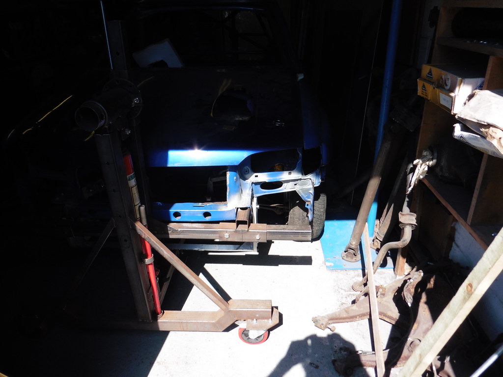 P1030771 P1030771 by jono_misfit, on Flickr on its wheels and bumper and lights back in  P1030772 P1030772 by jono_misfit, on Flickr There's something funky going on with the headlights to bumper interface that I need to look at. There is quite a gap at the inner end.  P1030773 P1030773 by jono_misfit, on Flickr and rear bumper on  P1030774 P1030774 by jono_misfit, on Flickr not much to show for a full, baking hot day! I should be able to roll it outside next time so I can have a bit of a clean / shuffle round the workshop. The floor desperately needs a repaint with a decent quality floor finish as it lifting in a number of places. |
| |
Last Edit: May 31, 2020 19:41:45 GMT by jonomisfit
|
|
jonomisfit
Club Retro Rides Member
Posts: 1,787
Club RR Member Number: 49
|
|
May 31, 2020 19:38:52 GMT
|
|
also. After so long on the spit / sill stands I forgot how low the car is.
Even when sitting up in the air on gravel springs on the rear and dodgy front legs with no engine it seems quite low and mean.
When on tarmac suspension its going to be quite low.
Having been researching I've determined the wheels and tyres i'm going to go for. Just got to wait for the credit card to recover from funding some house work!
|
| |
|
|
|
|
|
May 31, 2020 20:49:22 GMT
|
|
Back on its wheels! that is a milestone. Great job. When you bought the car, were you aware how much work needed to be done?
Keep up the good work
Peter
|
| |
|
|
Darkspeed
Club Retro Rides Member
Posts: 4,873
Club RR Member Number: 39
|
|
May 31, 2020 21:00:23 GMT
|
|
Nice one - it is good to have them sitting on wheels and tyres even if it is just a temporary thing between works.
|
| |
|
|
jonomisfit
Club Retro Rides Member
Posts: 1,787
Club RR Member Number: 49
|
|
May 31, 2020 21:40:38 GMT
|
|
I knew it was a bit rough and needed a rear leg replaced, which made me think it would need a lot of work.
It was fairly obvious despite the sellers attempt to hide it all with black underseal.
It's nice to have it on its wheels and make Brum Brum noises. But it won't be down for long. I'm mainly dry building a few bits to check before a final prep run.
|
| |
|
|
jonomisfit
Club Retro Rides Member
Posts: 1,787
Club RR Member Number: 49
|
|
|
|
This afternoons workshop time was mainly spent tidying up. started getting metal sheets into the sheet metal storage area / handy gap  P1030775 P1030775 by jono_misfit, on Flickr Cut the big Ali sheet in twain. I measured the floor length on the morris first, then measured agains, added a bit on, added bit more on, and cut. Then rammed in the gap...  P1030776 P1030776 by jono_misfit, on Flickr just fits this was the main reason for moving it. There is a lovelly dirt trap down the back and i'm starting the regular clean of the wrokshop to try and get the dust levels down for later in the year when I come to paint the car.  P1030777 P1030777 by jono_misfit, on Flickr I stripped all the stock off, cleaned the floor down, then re-packed the racks. Looking at some more pics on the web I noticed there are a lot of escorts with stiffener ribs between the master cylinders here. I may as well fit these now rather than get cracks post paint and have to clean back and weld.  P1030778 P1030778 by jono_misfit, on Flickr cut some steel strips  P1030779 P1030779 by jono_misfit, on Flickr change the shapes of the steel strips  P1030780 P1030780 by jono_misfit, on Flickr and weld in  P1030781 P1030781 by jono_misfit, on Flickr I'll have to have a re-visit next time in the workshop as I wasnt well lit and I missed my marks so the welds arent alligned. 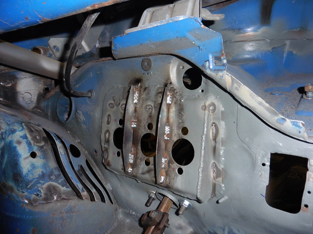 P1030782 P1030782 by jono_misfit, on Flickr I took care alternating sides on the welds to ensure the fences stayed vertical. I also clamped them to the backplate to prevent it pulling out of shape too much. Which was all relatively successful. |
| |
|
|
jonomisfit
Club Retro Rides Member
Posts: 1,787
Club RR Member Number: 49
|
|
|
|
Started building the car back up again to try and sort a few more bits  P1030783 P1030783 by jono_misfit, on Flickr  P1030784 P1030784 by jono_misfit, on Flickr car needs a clutch rest as otherwise there is the danger of resting the foot over the clutch or brake. will go in here  P1030785 P1030785 by jono_misfit, on Flickr sketch of what i'm after  P1030786 P1030786 by jono_misfit, on Flickr drawing some random lines on ali  P1030787 P1030787 by jono_misfit, on Flickr trim a bit  P1030788 P1030788 by jono_misfit, on Flickr will go in here  P1030789 P1030789 by jono_misfit, on Flickr the bottom corner sticks out too much  P1030790 P1030790 by jono_misfit, on Flickr trim it off  P1030791 P1030791 by jono_misfit, on Flickr boring flat piece of ali, now less boring 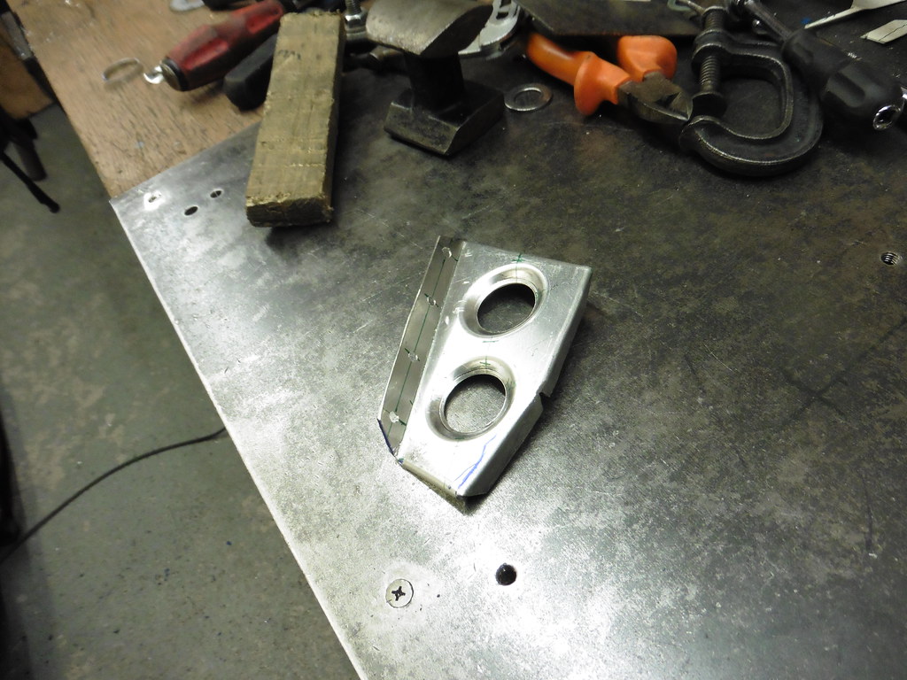 P1030792 P1030792 by jono_misfit, on Flickr Fixed in temp with self tappers  P1030793 P1030793 by jono_misfit, on Flickr its sitting too high and needs dropped about 30mm  P1030794 P1030794 by jono_misfit, on Flickr  P1030795 P1030795 by jono_misfit, on Flickr now needs stiffened up CAD  P1030796 P1030796 by jono_misfit, on Flickr in ali  P1030797 P1030797 by jono_misfit, on Flickr some folding  P1030798 P1030798 by jono_misfit, on Flickr holeified  P1030799 P1030799 by jono_misfit, on Flickr bracket assembled  P1030800 P1030800 by jono_misfit, on Flickr welding was tricky as I set the amps too high and melted it a bit fitted back in  P1030801 P1030801 by jono_misfit, on Flickr I'm going to move the fuse/relay panel to here  P1030802 P1030802 by jono_misfit, on Flickr card template  P1030803 P1030803 by jono_misfit, on Flickr goes in here like so  P1030804 P1030804 by jono_misfit, on Flickr ali cut  P1030805 P1030805 by jono_misfit, on Flickr ali more cut  P1030806 P1030806 by jono_misfit, on Flickr folded edges, bent over 90deg as its onto plastic and therefore its got a draft to it.  P1030807 P1030807 by jono_misfit, on Flickr in place  P1030808 P1030808 by jono_misfit, on Flickr it'll have a hinge on the bottom and some knurled bolts at the top so it can be opened easily. I then dug out the wiring loom. Which looks OK, but has been thoroughly chewed by vermin.... So i need to make a new loom. Joys.  P1030809 P1030809 by jono_misfit, on Flickr Still it'll do for what I need, which is to put the loom in place and work out how it needs to be modified to fit, and what needs stripped out. I'm on holiday this week, so may get a chance to do some more work mid week. |
| |
|
|
jonomisfit
Club Retro Rides Member
Posts: 1,787
Club RR Member Number: 49
|
|
|
|
today was the start of trying to work things out with the wiring. Which would be fairly straight forward if I had one of two things. 1) A wiring diagram for the right car 2) all the end devices that things plug into anyway, without either I carried on regardless the rats nest that is the engine bay / fuse/relay panel main wiring(which instantly looks like its been mucked about with)  P1030809 P1030809 by jono_misfit, on Flickr Identifying bits. What is quite nice is it already has wiring adaptors for Morretti twin round headlights, which I have a pair of (albeit needing some repairs and new lenses, but they are available)  P1030810 P1030810 by jono_misfit, on Flickr some bits near the turbo have got very very hot, burned insulation, and damaged wires  P1030811 P1030811 by jono_misfit, on Flickr Dug out the wiper and found the connection.  P1030811 P1030811 by jono_misfit, on Flickr the behind dash loom  P1030813 P1030813 by jono_misfit, on Flickr At this point I went for lunch, found images of the connectors for a few parts and sketched them out, and also downloaded a engine wirring diagram for 4 pot cosworth engines.  P1030814 P1030814 by jono_misfit, on Flickr then started trawling through the interior loom This bit is interesting. Its the feed for the fuel pump. Its been extended twice with some random black wire, then blue wire.  P1030815 P1030815 by jono_misfit, on Flickr and this is where its been cut from  P1030816 P1030816 by jono_misfit, on Flickr fitted the back lights  P1030817 P1030817 by jono_misfit, on Flickr and ran in the car loom. The fuel pump, fuel sender, and fuel sender will need stripped back through the loom and re-routed to where the tank is now.  P1030818 P1030818 by jono_misfit, on Flickr fuse box connector for the car loom  P1030819 P1030819 by jono_misfit, on Flickr then I put the engine back loom back in roughtly the right position to see if it'd help me determine any more of the connectors  P1030821 P1030821 by jono_misfit, on Flickr the huge black coil is the main ABS loom which runs to the passenger rear corner of the car. All of that will be getting removed as I wont have ABS. Much bodgery to the loom. My favourite bit so far are the cut off engine fan connectors that have been re attached with electricians connector block.  P1030822 P1030822 by jono_misfit, on Flickr there is a lot of wirring  P1030823 P1030823 by jono_misfit, on Flickr then I decided i'd not had enough wires today, so dug out the 24v granada loom  P1030824 P1030824 by jono_misfit, on Flickr and started puzzling my way through whats needed for the ECU etc.  P1030825 P1030825 by jono_misfit, on Flickr This is only the engine bay loom. there is a lot of it. Overall my 6hrs of wires today has lead me to consider the car wirring. The standard loom contains a lot of things I do not need. I don't need ABS, interior lights, stereo wiring (which I think it still in my loom but has just had connectors cut off), optional extra bits, etc. I've also got end devices that have either moved or the wirring will not suit what I have (front fog lights etc.), and the fuse / relay panel needs relocated. With this in mind I'm going to make a custom loom. I can use the existing loom for a template on lengths etc. and then customise it where I need. At the same time I'm going to attempt to simplify and split the loom. One for general car functions (lights, fuel pumps, etc.) and one for the engine. The intent being they are as Independent as possible with very clear cross connectors. What I really don't want to do is what ford do where things jump in and out of the various looms parts to get to a location with the minimum amount of wire and quickness of factory installation. This all needs thought out propperly though, so will need to dig back to my old electrical control system engineer days and design some layout and wirring diagrams. this may take some time..... |
| |
|
|
|
|
|
|
|
|
Have you revisited the pedal backplate yet? Because I can't see any holes in those reinforcing ribs...
|
| |
|
|
jonomisfit
Club Retro Rides Member
Posts: 1,787
Club RR Member Number: 49
|
|
|
|
|
There's not enough space for swaged holes so my enthusiasm for drilling it is low.
However I've noticed I could sneak a few small ones in on the pedals though 😁
|
| |
|
|
|
|
|
|
|
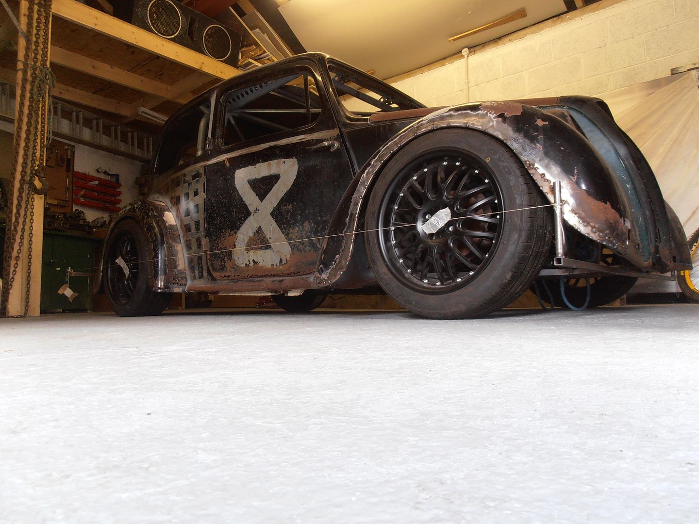
monster progress, well done  whats the motives for the abrupt car-ey-ness you are working on? the connector block thing made me smile (chocolate block) the only thing i ever seem to do with them is strip the plastic off and used them to join bowden cables. cant say ive ever used to for transporting electricities  |
| |
|
|
jonomisfit
Club Retro Rides Member
Posts: 1,787
Club RR Member Number: 49
|
|
|
|
monster progress, well done  whats the motives for the abrupt car-ey-ness you are working on? the connector block thing made me smile (chocolate block) the only thing i ever seem to do with them is strip the plastic off and used them to join bowden cables. cant say ive ever used to for transporting electricities  I'm getting near to needing to put paint on the car so I want to ensure any hot work is complete first. Hence the build up. I've identified a few bits that need welding already (transit points for fuel and cables). Not just chocolate block, but domestic / industrial 240v wire as well. Proper bodgery. Oh and bad soldering too. |
| |
|
|
|
|
|
|
|
|
It will be a lot neater if you can keep the wiring which goes across the car inside rather that the original which had a great bundle of wires clipped to the top of the upper bulkhead part of which was above the turbo thus getting cooked when the heat shield was left off or fell to pieces as you have seen.
Making a separate vehicle and engine harness also makes it easier if you want to change the powerplant at any time in the future.
What are you doing for instrumentation?, will the escort cluster work with the v6 powertrain? If it is likely to be a problem I would do the instruments as a sub loom, bring every input you are ever likely to need to a connector on the vehicle side then you can pick and choose whatever you need for your chosen instrument package.
|
| |
|
|
jonomisfit
Club Retro Rides Member
Posts: 1,787
Club RR Member Number: 49
|
|
Jun 10, 2020 10:35:45 GMT
|
I think its quite likelyy my wirring will still run across the enginebay side of the bulkhead, for ease of access if nothing else. However I'm going to attempt to run the wirring at the back of the bulkhead recess rather than at the front. Which keeps it out the way as much as possible. I'm also going to run it up in the inner wing to turret gap, again to keep wires away from the the engine heat source. Thats the main thinking with splitting the looms. At the moment its getting this engine / ECU, however in the future its likely to have something different and I want to make it as easy as possible to swap out things. The chassis wirring should stay pretty constant. It should be a consistent set of signals both way really, irrespectice of engine/ECU. Instruments are going to be pretty basic. I found a nice TFT display set that has all lights / alarms / warnings / Revs / speed, so i think I will go for that. I was tempted to just go for a large rev counter and minimal everything else. But will see how will and funds progress. www.aimtechnologies.com/mxg-strada-1-2/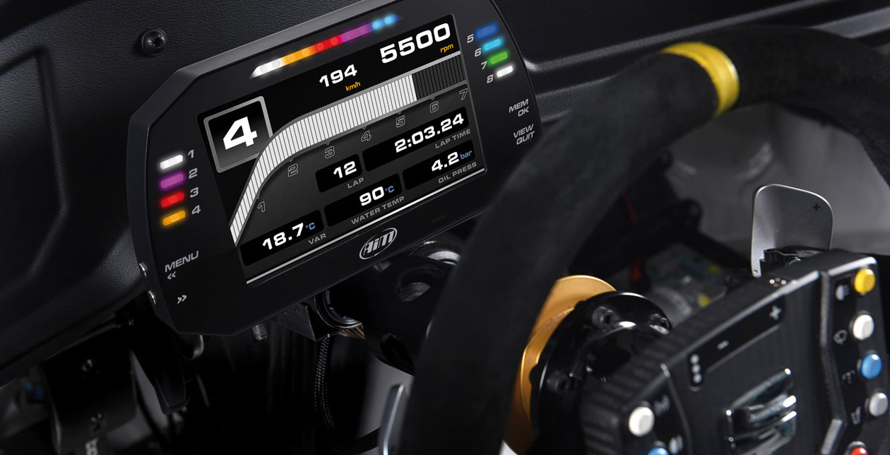 |
| |
Last Edit: Jun 10, 2020 10:48:30 GMT by jonomisfit
|
|
jonomisfit
Club Retro Rides Member
Posts: 1,787
Club RR Member Number: 49
|
|
Jun 10, 2020 13:26:17 GMT
|
This probably isnt how youre meant to do car wirring, but i've started putting together my diagrams to help me understnad how i'm going to wire it all together. 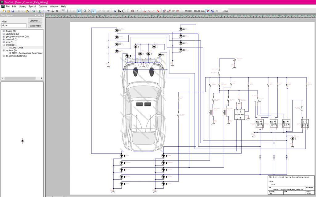 |
| |
|
|
|
|
|
Jun 10, 2020 15:23:19 GMT
|
|
Good work, and while it may seem like a non-sequitor, I'd ask that you keep showing us as much of this electrical stuff as I've asked GN to show us his trim/upholstery tactics; both are areas many of us could use some schooling, me especially.
Also, forgive me if shown earlier in the thread, but do you use a dedicated dimple-punch-press, or just cut the hole and form the dimples with other random tools?
Thanks, John
|
| |
|
|
jonomisfit
Club Retro Rides Member
Posts: 1,787
Club RR Member Number: 49
|
|
Jun 10, 2020 16:15:24 GMT
|
|
I'm happy sharing most things I do, although most of it I make up as I go along so not likely to be best practice!
The wiring will be no exception, and going by the circuit digrams on the web i'm doing things pretty A-typically already.
I have a set of hole swage dies I bought off Ebay that I use. I think they were from Dimple Dies UK. they are OK. not the best, and mine have been thoroughly abused but they work :-)
The advantange of the ones i have is the second step really stiffens the folded hole edges, the downside is they move more material so the panel ends up stretching in places.
|
| |
Last Edit: Jun 10, 2020 16:16:38 GMT by jonomisfit
|
|
Phil H
Posted a lot
  
Posts: 1,448
Club RR Member Number: 133
|
|
Jun 10, 2020 16:57:54 GMT
|
|
I've seen many different sets of schematics over the years - that's as good an any, logical and more importantly as you're the one designing it, you should also understand it both now, during the build and in 3 years time when trying to find a weird fault (that won't be an issue with the loom itself but you WILL doubt yourself).
Don't forget rule number 1 - always allow for more circuits than you think you need. Then allow for some more to be tagged on after that.
You can do it all in one colour cable (saves trying to find 30+ bespoke colour combinations), but if you do don't forget to label each and every wire with something VERY hardy - colour coded wire markers might look odd in a car loom, but even if the number wears off, the plastic colour will have to fade an awful lot before you can't tell what it was. You're' designing something bespoke to do a particular job so has to be maintainable.
|
| |
|
|
 P1030735 by jono_misfit, on Flickr
 P1030736 by jono_misfit, on Flickr
 P1030737 by jono_misfit, on Flickr
 P1030738 by jono_misfit, on Flickr
 P1030739 by jono_misfit, on Flickr
 P1030740 by jono_misfit, on Flickr
 P1030741 by jono_misfit, on Flickr
 P1030743 by jono_misfit, on Flickr
 P1030744 by jono_misfit, on Flickr
 P1030745 by jono_misfit, on Flickr
 P1030743 by jono_misfit, on Flickr
 P1030746 by jono_misfit, on Flickr
 P1030735 by jono_misfit, on Flickr
 P1030736 by jono_misfit, on Flickr
 P1030737 by jono_misfit, on Flickr
 P1030738 by jono_misfit, on Flickr
 P1030739 by jono_misfit, on Flickr
 P1030740 by jono_misfit, on Flickr
 P1030741 by jono_misfit, on Flickr
 P1030743 by jono_misfit, on Flickr
 P1030744 by jono_misfit, on Flickr
 P1030745 by jono_misfit, on Flickr
 P1030743 by jono_misfit, on Flickr
 P1030746 by jono_misfit, on Flickr




 whats the motives for the abrupt car-ey-ness you are working on?

