|
|
|
|
|
|
So, one step forwards two steps back.
Have a new idea about the cooling. Found that the end-clearance eon the impeller is supposed to be 0.8-1.2mm, which will be quite critical for flow at low rpm. I'm wondering if a combination of sealant on the gasket and manufacturing tolerances might mean that the gap's a bit wider. Unfortunately that'll mean coolant system apart again (has to be up to half a dozen times now...).
Next step backwards is I've just done a compression test and it's not brilliant news :S not sure what they typically are on these engines, but I'm not a fan of the difference between cylinders...
Cylinder 1: 9 bar
Cylinder 2: 8 bar
Cylinder 3: 9 bar
Cylinder 4: 9.8 bar
1.8 bar difference isn't terribly promising. Will check valve clearances, but starting to look into bits for engine rebuilds :S
|
| |
|
|
|
|
Darkspeed
Club Retro Rides Member
Posts: 4,884
Club RR Member Number: 39
|
|
|
|
|
Do a leak down test much better way of indicating where there may be an issue.
Are those the results from a cold test W.O.T - or a HOT test W.O.T? Do both if not. Then the teaspoon of oil ring seal test and see what the averages are.
Yep - water pump capacities/efficiencies are all about impeller diameters and housing clearances.
|
| |
Last Edit: Oct 5, 2019 20:15:05 GMT by Darkspeed
|
|
|
|
|
|
|
Valve clearances seem to check out. Near as damnit 0.5 exhaust 0.4 inlet which is slap bang in the middle of the haynes figure which seem to check out from a bit of googling. Ordered a decent leakdown tester to will try that next. Compression tests were done on a hot engine, working from 1 back to 4. I'm guessing the leakdown is also done on a hot engine? And yeah, figured it would be similar to oil pumps where end-clearance is critical for flow and pressure. Will pull that apart and check as soon as there's a garage space available  |
| |
|
|
Darkspeed
Club Retro Rides Member
Posts: 4,884
Club RR Member Number: 39
|
|
|
|
|
For some reason the site has corrected W.O.T (wide open throttle) to "what" - W.O.T. A PITA
|
| |
|
|
|
|
|
|
|
Haha I thought that was an 'or what'  Didn't do it at W.O.T actually. Will check how much of a difference that makes (there's a haynes figure of 11 bar for a compression check). TBH I'd always thought it breathed a lot through the catch tank so I'm not particularly hopeful... |
| |
|
|
Darkspeed
Club Retro Rides Member
Posts: 4,884
Club RR Member Number: 39
|
|
|
|
Haha I thought that was an 'or what'  Didn't do it at W.O.T actually. Will check how much of a difference that makes (there's a haynes figure of 11 bar for a compression check). TBH I'd always thought it breathed a lot through the catch tank so I'm not particularly hopeful... It can make a significant difference. |
| |
|
|
|
|
|
|
|
Interesting. Will try that next and see if the 9.8 piston gets up to 11 or so. Or just wait until my leakdown tester arrives and test it properly with and without oil in the bores. Still holding out for it not being rings as they look like they're a little tricky to find! Might do a quick dummy check cranking with my hand on the dipstick hole and see if there's pressure. In other news, I've got the MG F back on the road  turns out the crack wasn't just in the upper area but along one of the horizontal mounting points as well. 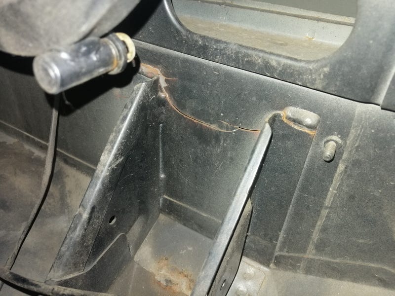 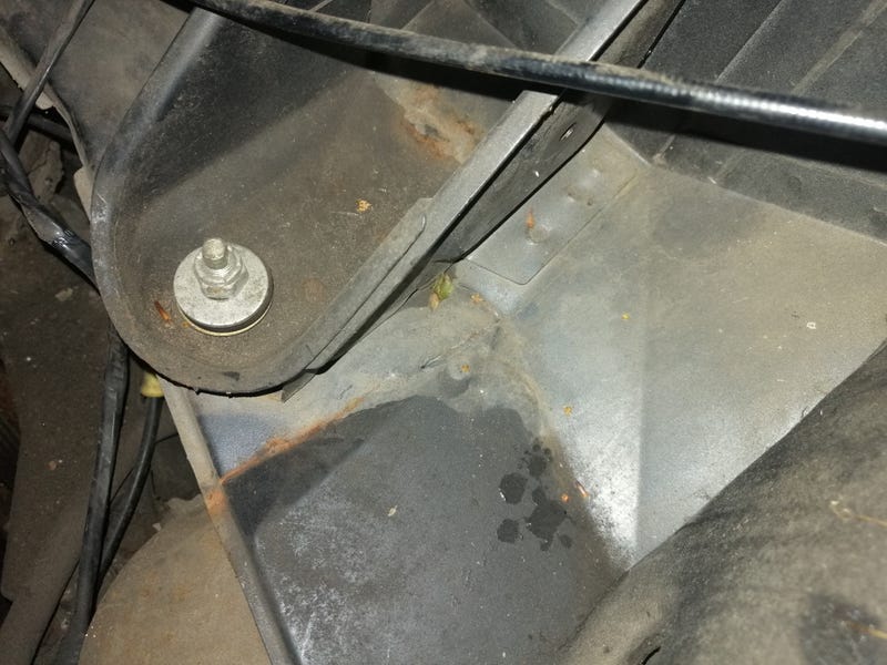 I'd bought a strengthening kit from Mike Satur which mirrors the Cup cars' setup, but looking at it I'm not sure it'll fix my particular problem.  Judging by where mine had cracked, I reckon what happens is the forces fatigue the bit where the standard rear brace meets the bodyshell, and because it's not braced across the two it can do that relatively independently. Once that's gone, then it just works it's way more and more loose along the top and down at the base. The Mike Satur kit would prevent this by bracing the two together so they don't flex independently of one another. Unfortunately, because mine's already gone it's probably likely to just punch the now-stiffened bracing clean through the weaker bits I've repaired around it :S What we need is something to spread the load out a bit. Something a bit like this: 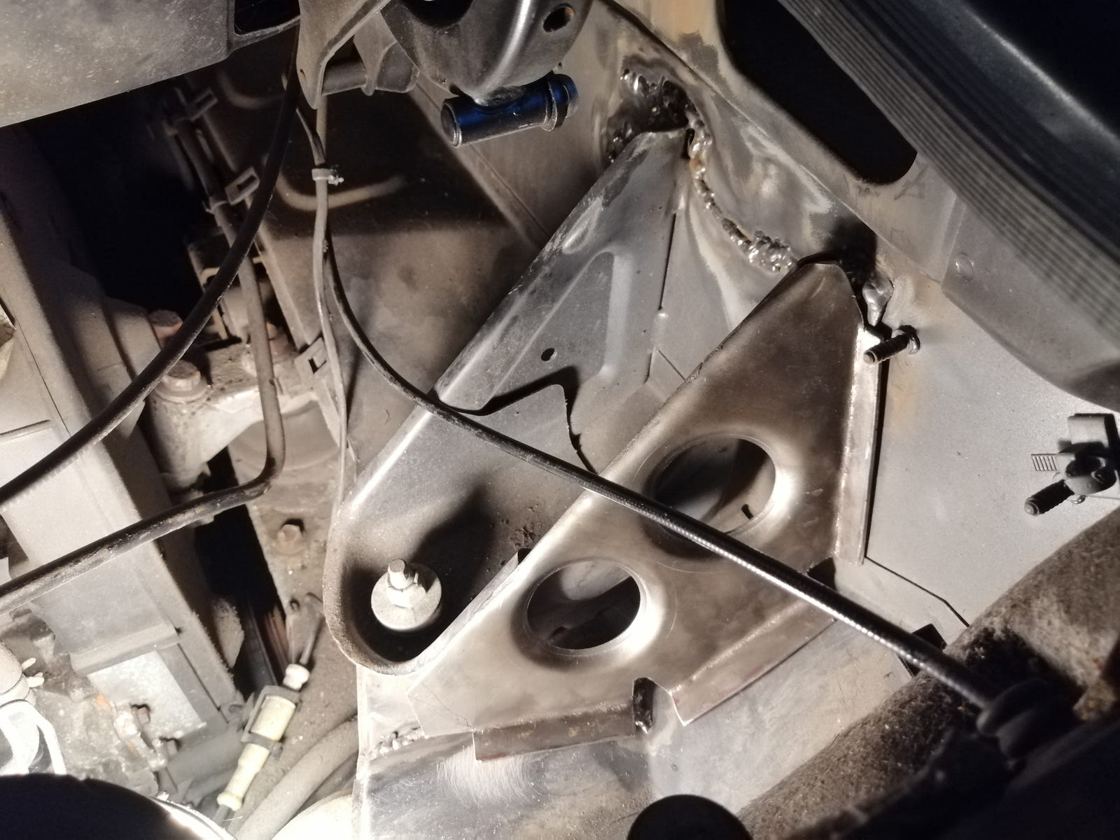 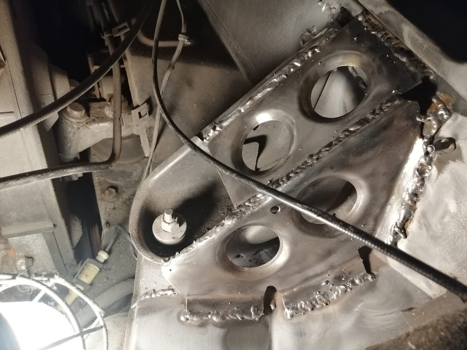 That should do it ok  Adds additional points where it's connected to the bodyshell that are outside the fatigued areas. It's also usefully lighter than the Mike Satur one (understandable, given the latter needs to be batch produced). 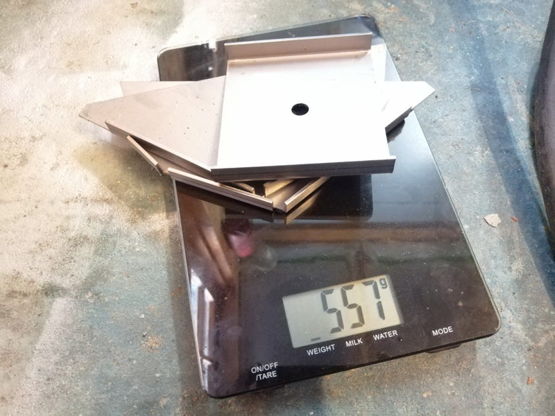  Oh, and there's nothing like swaged holes to make something look proper. It's like parsley. Take a regular tomato soup and it's just plain, but add a sprig of parsley to the top and suddenly you look like a bit of a chef. Same thing with swaged holes  |
| |
|
|
Darkspeed
Club Retro Rides Member
Posts: 4,884
Club RR Member Number: 39
|
|
|
|
|
Yes - Strengthening the bracket when the bracket has not failed will certainly not do anything for your particular failure - Has it happened the other side? Looks like the failure path is in the material strengths that the bracket is attached to. If that's a damper connection it could be that damper rebound is a bit firmer on that side as it looks like a failure ability to retain rebound forces rather than bump.
|
| |
|
|
|
|
|
|
|
Yeah I didn't think it would help! Interesting about the rebound not being strong enough. Didn't think of that, but it certainly fits with how it's fatigued and where it sat at rest (bracket pulled inwards). Not overly surprised it's failed really, given that the horizontal panel is simply one layer of stamped 1.6mm steel, and I expect the vertical is not much better. Hopefully spreading the load out a little, and a little closer to the joins between other planes and changes in plane will stop it cracking again. Honestly, I'm quite enjoying getting back to fabricating. All this visualising load paths is fascinating  |
| |
|
|
|
|
|
|
|
|
I have quite a bit of experience with body failures like this, it looks to me like the flanges are being pulled away from the vertical face (vertical in the photos) as the flanges are in the middle of a flat panel the flat panel will flex and fatigue cracking in the way you have seen.
the new top reinforcement will take the load in the the perpendicular face this will be much stiffer and better at resisting the flex and consequent fatigue, if you want to make it even stronger make the reinforcement wider so it has a longer connection and spreads the load over a greater distance at the top.
|
| |
|
|
|
|
|
|
|
|
|
Oh, and there's nothing like swaged holes to make something look proper. It's like parsley. Take a regular tomato soup and it's just plain, but add a sprig of parsley to the top and suddenly you look like a bit of a chef. Same thing with swaged holes  Going by that analogy, jonomisfit has just made a giant salad? |
| |
|
|
jonomisfit
Club Retro Rides Member
Posts: 1,790
Club RR Member Number: 49
|
|
|
|
|
More of a colander 😁
|
| |
|
|
|
|
|
Oct 11, 2019 15:47:34 GMT
|
Haha 'colander' did make me chuckle  pretty good descriptor too!  kevins kevins Glad I'm on the right track reinforcing it. Well aware that I'm largely eyeballing my chassis reinforcements without any recourse or experience with CAD or element modelling. Only really 'headphysics modelling' to try and work out which way the forces should go. Fiat updateSo, not much further forward with the Fiat. Leakdown tester's arrived but not got round to using it yet (read a forum thread with someone with dodgy compression that turned out to be a cracked exhaust valve so still some hope yet!). Spit updateAfter watching an episode of Project Binky where they made some very good points about not painting their car before they've done a full dry fit of components to avoid damaging a good paintjob I've decided they might have a point. Besides, I'm tired of sanding paintwork! So, a bit of musical chairs and the Spitfire's back where she belongs. 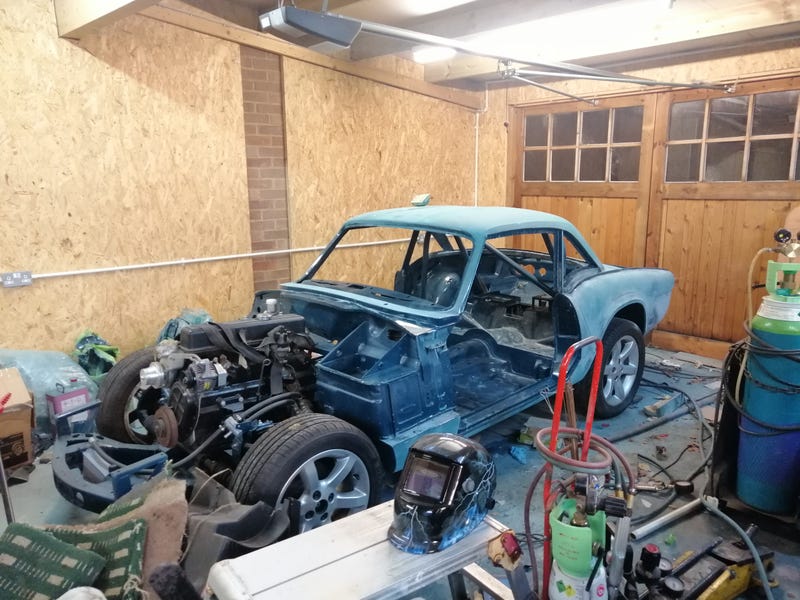 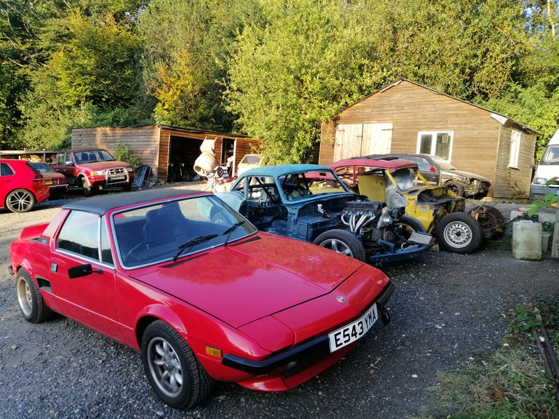 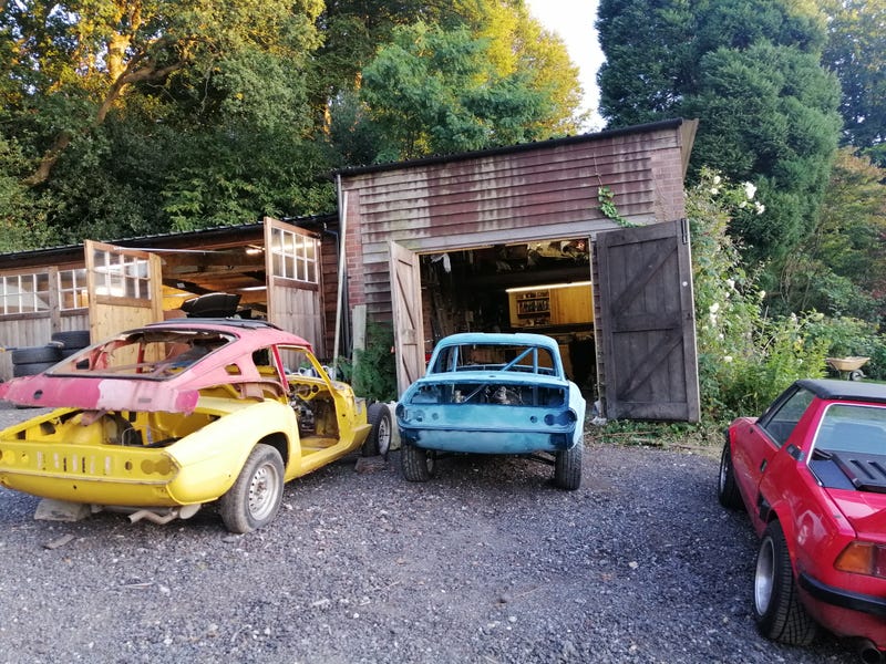  First order of business is relocating the fuel tank. Before I'd read up on the IVA requirements I'd plumped for a GT6 fuel tank in the boot and used the space where the old tank was for better rollbar locations, space for the battery and space for the fuel pumps and swirl pot. Unfortunately, I doubt the IVA people will like the fuel tank being in a place with such little crash protection so it's got to move. There are positives to this. I get my boot space back. Although the weight distribution will be shifted forwards, it'll help a lot with polar moment of inertia. Oh, and less chance of a fiery death of course (drove past a burnt out new MINI today which reminded me to take this stuff seriously!). I thought about putting the battery and fuel pumps in the boot, but the crash protection and polar moment of inertia arguments came up again so they're going on the parcel shelf behind the seats.  My thinking is battery on the left to balance the weight of the driver, and making up a fibreglass box of some sort to isolate the electrics from the cabin. I seem to remember IVA liking a metal bulkhead of some sort between fuel setups and the cabin so would welcome some input for that. Would a fabricated and sealed metal box to go over the fuel pumps be enough, or does it need to be completely separate from the cabin? If it's the latter I might see if I can position them underneath the floor of the car itself (might work better that way anyway...). While that thought's rattling around I figured I'd sort the battery. Fits quite snugly in its space already, but a decent tab on the front to hold it there... 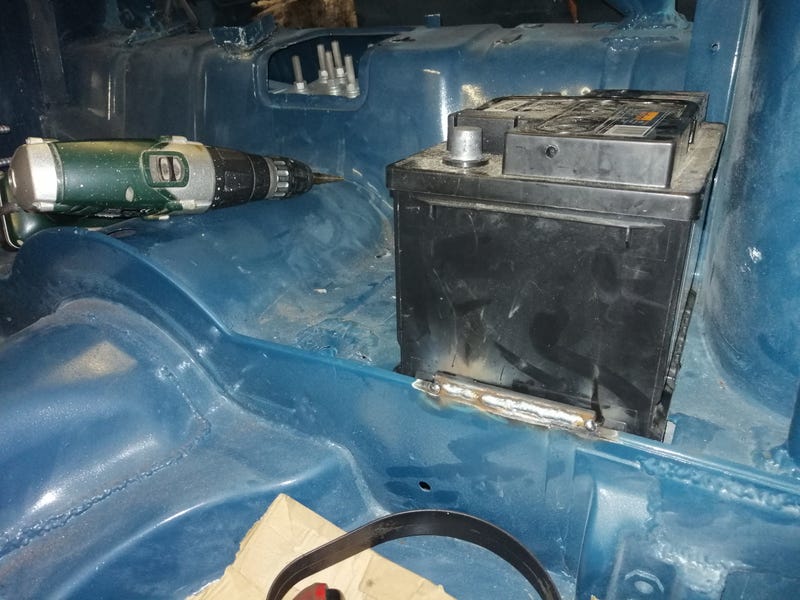 ...and a beefy bolt-on clamp at the back should keep it in place. 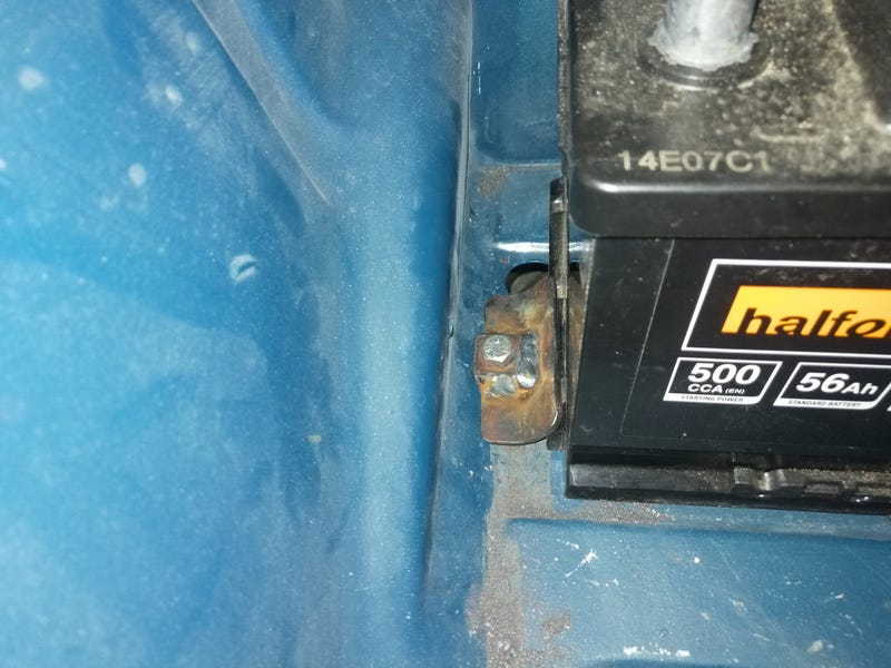 I've also added a spreader plate underneath the body so it doesn't just pull through the floor in the event of a crash. Will also add some verticals to the clamp itself to stop it bending upwards and letting the battery go as well. Feels nice to be working on this thing again  |
| |
|
|
Darkspeed
Club Retro Rides Member
Posts: 4,884
Club RR Member Number: 39
|
|
Oct 11, 2019 21:18:53 GMT
|
IVA has no say in the location of the tank re crash protection - All that is required is a physical barrier between it and the passenger compartment and that its not good form to have a row of spikes on the chassis that would puncture the tank in a minor bump. Pumps fuel lines or anything like that through the passenger compartment is a complete non no for quite obvious reasons. The Fury/Westfield/Caterham/Gemini etc. etc. only have a flimsy bit of Alloy / Glassfibe between the tank and the external forces. It just needs a physical barrier between it and the occupants so reduce the chance of the occupants being doused in fuel in the event of an impact. Batteries should not really be in the passenger compartment - It's a bad idea as not only will just rip themselves free in a crash but they also produce an explosive gas called Hydrogen - if in a passenger compartment they should be in a sealed container vented externally. A battery is just a semi stout plastic case holding a  load of lead and acid - holding it down to the floor by the edge of that case will do very little in an impact. Speaking to an IVA man he said here's a simple rule - "If you don't find it done that way in a modern car your mum would drive everyday then chances are it wont pass." And that pretty well holds true. |
| |
|
|
|
|
|
Oct 14, 2019 10:43:30 GMT
|
|
Huh, interesting on the tank location. Remember reading in the guidance about crash protection for the tank, but I suppose there's a lot of interpretation as to what that means in practice. Either way, relocating it further away from a crash area would be a good idea.
Gotcha on the fuel stuff in the passenger compartment. I was thinking of making up a metal box that goes over it with an access panel somewhere, but if they can fit under the floor then that's much better. If not then maybe in the boot would be good as I've got some space to spare now.
I know about the batteries outgassing. It's something a lot of battery-in-boot installs don't do properly either. Not only can it let off hydrogen into the cabin, but they leach a little acid as well which can rust things out pretty quickly. That's usually the reason the battery boxes in the back of E36s are rotten through. There's an existing hole in the floor which I'll put vent tubes through, and it'll be sealed in its own battery box.
Hmmm, you're right about the battery. I'd copied the setup on my MGF which just has a little clamp on the plastic bits (my Alfa does too), but I suppose they're not in the cabin. I'll see what I can do about making a second clamp setup and probably a stouter box around it than I was planning previously so that if it does break free it's still contained away from the passengers.
|
| |
|
|
|
|
|
Oct 22, 2019 15:58:04 GMT
|
Battery tray sorted  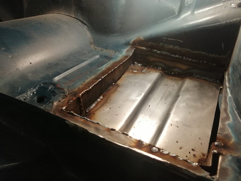 I've dropped it down about an inch or so into the bodyshell so one rear corner is resting on the chassis, and the other is welded to the flange on the underside of the wheelarch. Should mean I have space above to make a proper clamp that goes above the battery, and it's a bit better secured at the base anyway. 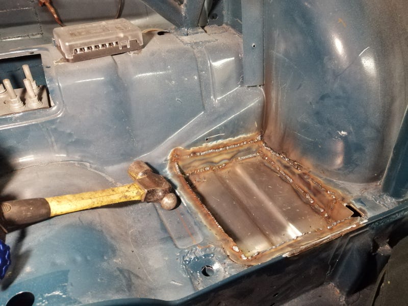 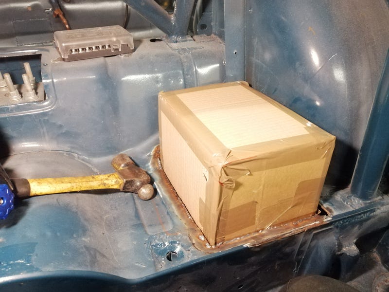 Next up is the fuel pump setup. I've mocked everything up underneath the bodyshell and decided there really isn't enough space for a lift pump, swirl pot, high pressure pump and filter all under there. So, I think I'll do away with the lift pump and have it as a gravity-fed sump below the level of the tank. If I'm smart with multiple feed lines from the main tank and plumbing the return line back into the sump rather than the main tank I should be able to avoid fuel starvation in corners. I will need to fabricate a sump that fits closely to the bodywork though, otherwise it'll be either too small to be useful or poke out beneath the bottom of the car and be vulnerable to stray twigs and the like. What do people think? |
| |
|
|
|
|
|
Oct 25, 2019 10:23:31 GMT
|
Mocked up a CAD model of the sump, and have a question for people...   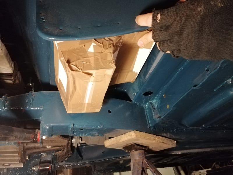 There's definitely not enough space to fit the lift pump down there too, but if I scallop the body I should be able to fit both the high pressure pump and filter down there. At ~1.4l it's also a little bigger than I thought which is nice. My question is about whether the design is sound. So, plan A is to run a fat fuel hose down from the tank to the highest point in the sump which feeds the HP pump. I'd then have the return from the fuel rail come back to the sump so the only demand from the feed hose is whatever fuel the engine consumes. Hopefully any overpressure from the pump return or air bubbles would bleed back up the feed hose so I'd only need 3 connections. I think I've worked out that if I have a 15mm feed hose then at ~0.03 bar pressure from gravity I should have ~258l/hr of flow, which is a little over the ~240l/hr I can get from the 8mm high pressure fuel line at 3 bar for the rest of the system so even at the most extreme it hopefully shouldn't be able to empty the sump. At a very rough estimate (200bhp x 2.64l/hr) my engine should use about 75l/hr of fuel so it should definitely be able to keep up with that. Considering all that, do you reckon I'd need still need a lift pump? Plan B would be to try and find somewhere between there and the fuel tank to place the low pressure pump. Only real issue is a redtop-style pump is a bit bulky to fit anywhere so if anyone knows of any more compact inline low pressure fuel pumps that would be great! Main reasons I want to avoid a second pump are space, more complicated fuel lines and wiring, and redtops weigh about 700g so if I can cut that out then I'm a fair bit lighter  |
| |
|
|
scimjim
Club Retro Rides Member
Posts: 1,503
Club RR Member Number: 8
|
|
Oct 25, 2019 12:50:41 GMT
|
What tank are you using? Can you access the top face and fit an in-tank pump and sump from a modern? I bought a complete Nissan micra tank and chopped out the plastic securing ring and raised thread to graft into a stainless tank.  also, what about foam filling? I hillclimb a car with a zetec fitted and don’t have a lift pump or swirl pot, just a feed from the bottom of the foam filled tank. |
| |
|
|
|
|
|
Oct 25, 2019 13:08:54 GMT
|
Nice idea  I was planning on using either the standard Spitfire tank or more likely a steel tank of my own construction that fits roughly in the same place. The main reason I was keen for an external pump setup is I'll have to chop into the stock tank quite significantly to fit it around the roll bar backstays. It's only 33 litres from standard which isn't the biggest tank to begin with, and I'll probably cut a good 5 litres out of that so I'd like to keep as much capacity for fuel as I can! I'll probably be able to gain some back by making my own tank as the stock tank has quite a big lip around the edge, and the sump being 1.4l helps too. I'd like something closer to 40l but we'll see! Same goes for foam, although it is a neat solution. |
| |
|
|
goldnrust
West Midlands
Minimalist
Posts: 1,889
|
|
Oct 25, 2019 15:49:58 GMT
|
|
If you're thinking of making up a custom tank, and you're not scared to cut bits out of the shell, could you make a drop down sump as part of the tank? Similar to the set-up they've made for Project Binky? (https://www.youtube.com/watch?v=I_ajcKhHLjU)
|
| |
Last Edit: Oct 25, 2019 15:50:41 GMT by goldnrust
|
|
|
|




 load of lead and acid - holding it down to the floor by the edge of that case will do very little in an impact.


