|
|
|
|
|
|
However, this is well before being proudly badged SOLID STATE.
Thermionics are fun. Slightly less pleasant to touch accidentally ground-to-B+ than equivalent transistor circuits, but they age gracefully. They sound better when turned to maximum, also.
Phil
|
| |
|
|
|
|
|
|
|
|
|
|
Understanding and repairing that is SERIOUSLY impressive to me. John
|
| |
|
|
|
|
|
|
|
It's all just squiggly-Amps. eBay has lightened my wallet again, this time to the tune of a 1956 Delco radio, Buick fitment (same as this but inverted). 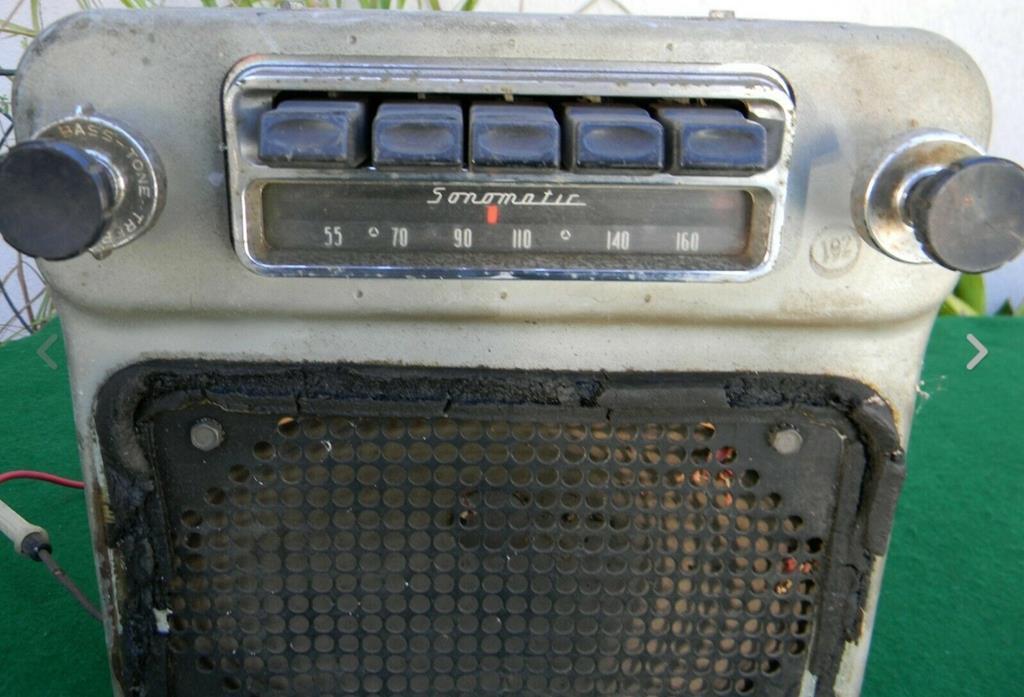 I'm hoping to make one good set from the two, correctly converted to 12V. Phil |
| |
Last Edit: Apr 9, 2019 12:51:00 GMT by PhilA
|
|
|
|
|
Apr 10, 2019 23:20:56 GMT
|
Tonight we revisit the oily bits. 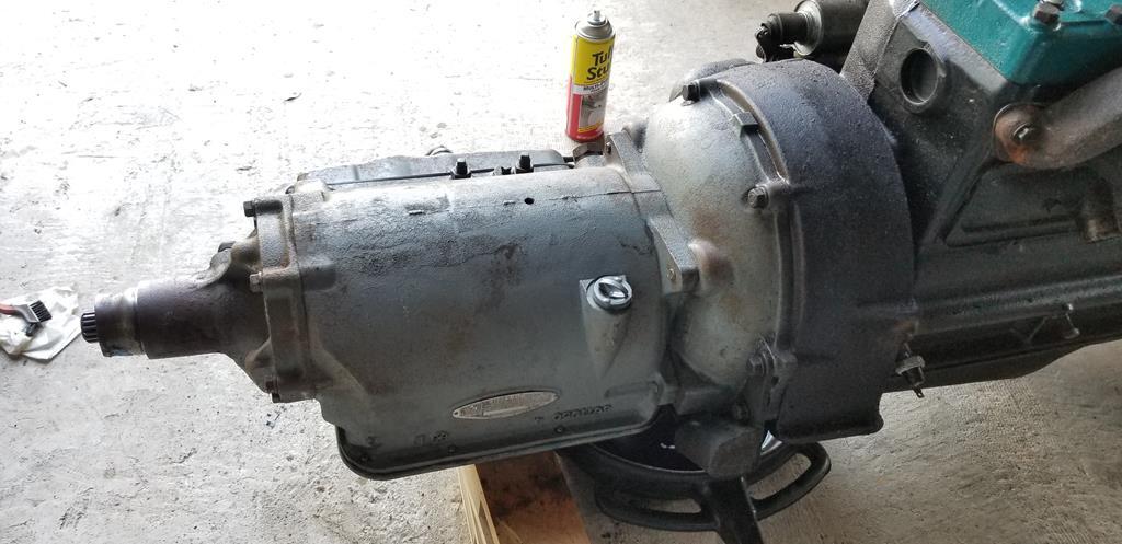 Or, rather, the much less oily bits. Manual states everything must be scrupulously clean before disassembly. Need some proper engine degreaser really. Carpet shampoo does a good job but has trouble with the thick gungy stuff. Phil |
| |
|
|
|
|
|
|
|
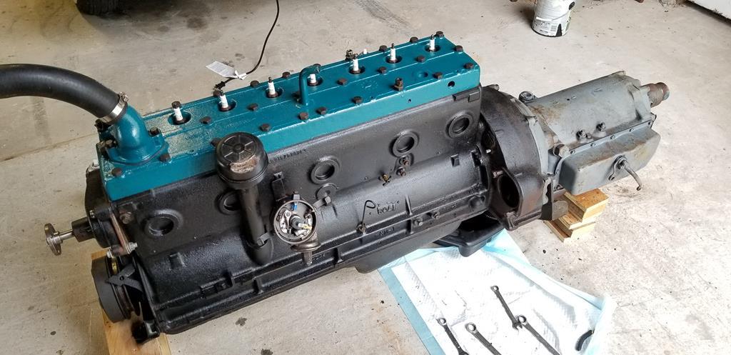 Stripped the ancillaries off the engine. 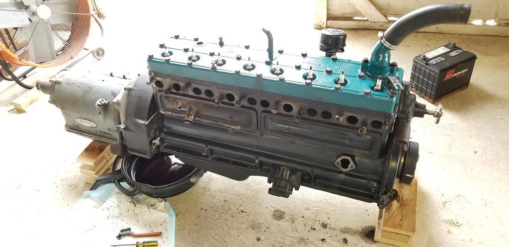 Started to clean all the grime. Other side next, then it'll be time to drain and split the gearbox. Phil |
| |
|
|
|
|
|
Apr 13, 2019 14:59:10 GMT
|
|
FedEx had a sudden bout of efficiency and moved Monday's delivery up to today.
Typically the day I have to go out to go shopping.
Phil
|
| |
|
|
fer4l
Posted a lot
   Testing
Posts: 1,497
Club RR Member Number: 73
|
1951 Pontiac Chieftainfer4l
@fer4l
Club Retro Rides Member 73
|
Apr 13, 2019 16:16:19 GMT
|
FedEx had a sudden bout of efficiency and moved Monday's delivery up to today. Typically the day I have to go out to go shopping. Phil Better than the other way around... |
| |
|
|
|
|
|
Apr 14, 2019 12:22:10 GMT
|
 A box arrived! Labeled fragile, that's the way to get something fragile broken, in my experience. 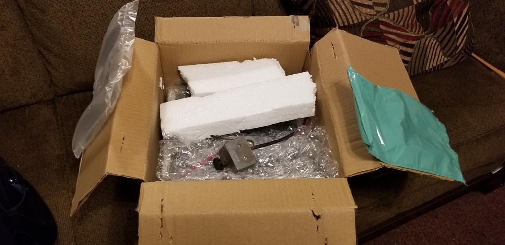 Cut through the tape and opened it up. 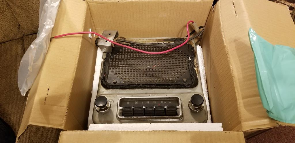 Contents: One radio. 1956 Buick, again made by Delco. 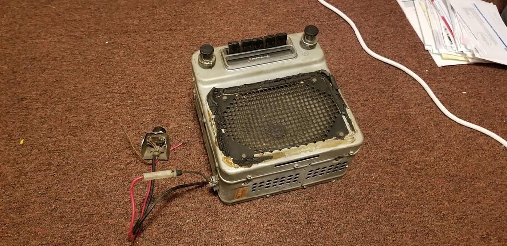 It's in really very good shape, apparently having lived its whole life in California. 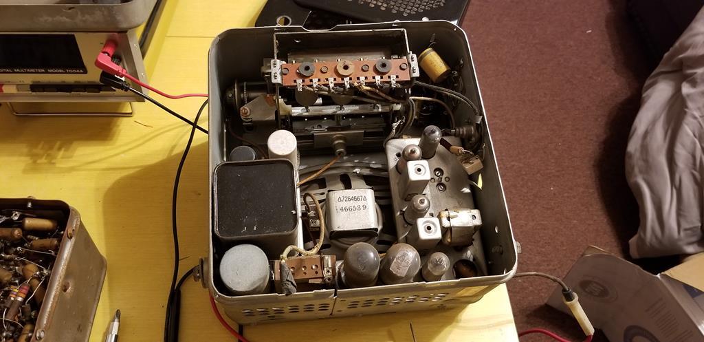 Popped the back off. Looks to be ok, apart from one thing; 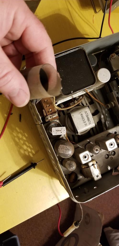 Well, that bit there is definitely meant to be attached to something. 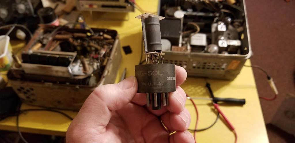 Yup, it's meant to be attached to this. Remember that fragile sticker? Heh. It's a Tung-Sol 12V6 power beam pentode. Part of the audio output circuit. 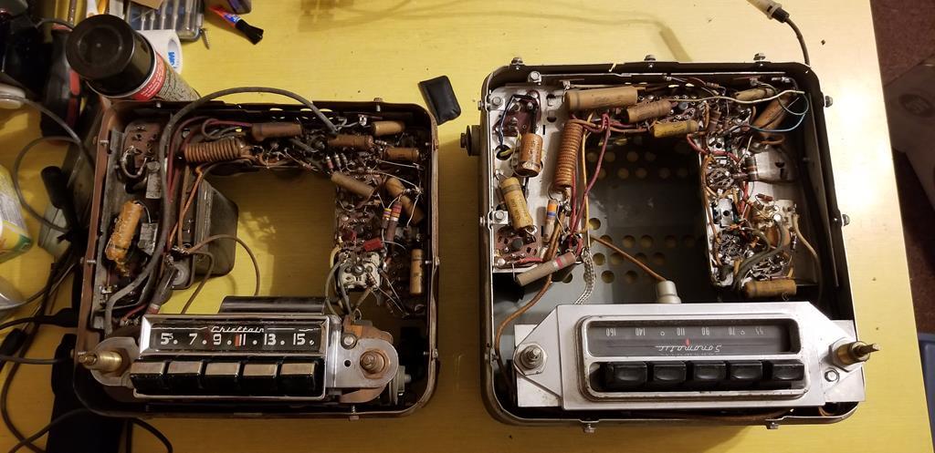 Side by side against the 1951 radio- oddly the '51 design is better (but more complex). Definitely some cost-cutting going on by '56. 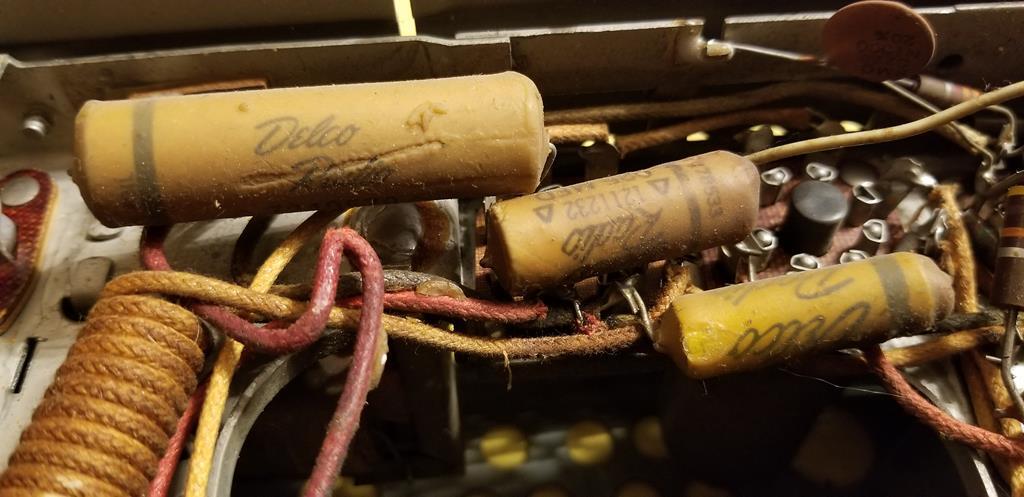 It looks like that radio went in to a shop for service (there is a handwritten pencil note on the top "pops on and off", so it had problems) and never left, having had no work done on it. That one broken tube aside it appears to have never been touched (Delco tubes were original, Tung-Sol not so). It looks like it should be perfect to convert my radio correctly to 12V. Phil |
| |
|
|
|
|
|
Apr 14, 2019 16:41:27 GMT
|
|
scary stuff....and i thought circuit boards looked complicated!!
|
| |
'80 s1 924 turbo..hibernating
'80 golf gli cabriolet...doing impression of a skip
'97 pug 106 commuter...continuing cheapness making me smile!
firm believer in the k.i.s.s and f.i.s.h principles.
|
|
|
|
|
Apr 14, 2019 23:28:01 GMT
|
|
Parts radio works. Class B single ended output there because we're only on a single output tube, but that's not bad for being switched on and asked to work for the first time in probably 40 years.
Phil
|
| |
|
|
|
|
|
|
|
|
Yup. I was quite surprised that it worked at all...
Still, it does prove one thing- it's a good donor for the parts I need to make the other radio run.
Phil
|
| |
|
|
|
|
|
|
|
Radio scrapyard begins. 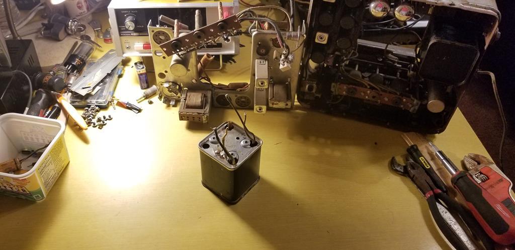 That big old tin of spam contains the 12V power transformer (6V one still mounted in the other radio there). It also contains a big old paper capacitor that, in that position in the circuit is well known for going up in smoke. It's tempting to use a can opener to get into it... The two chassis look about the same size, they may even be interchangeable in the frames. I'm resisting putting the simpler 12V chassis in just because it's easier to work on. I need to buy some gas for my torch so I can un-solder the ground strap and pull the 6V chassis out to work on. Phil |
| |
Last Edit: Apr 15, 2019 4:19:11 GMT by PhilA
|
|
|
|
|
|
|
Loving this  |
| |
|
|
Frankenhealey
Club Retro Rides Member
And I looked, and behold, a pale horse! And its rider's name was Death
Posts: 3,888
Club RR Member Number: 15
|
1951 Pontiac ChieftainFrankenhealey
@frankenhealey
Club Retro Rides Member 15
|
Apr 15, 2019 10:26:58 GMT
|
Loving this  What he said plus I get the feeling that when the Apocalypse comes you will be one of the survivors. |
| |
Tales of the Volcano Lair hereFrankenBug - Vulcan Power hereThe Frankenhealey here |
|
|
|
|
Apr 15, 2019 12:40:45 GMT
|
|
Well, I was doing a little reading and research between circuit phase inversion and transformer phase inversion.
Seems there's two schools of thought going on here. Some people prefer a transformer design, claiming superiority because it has a very low input impedance and means you can run in class AB2 ("grid current") mode and make the very most of the capabilities of the power output tubes.
Using a circuit to do the same is a cheaper alternative because it uses a few electronic components. It however recreates a more honest representation of the original signal with less distortion, class AB1.
Blah blah blah electronics. The '56 radio is louder and uses a more reliable method of phase inversion.
Phase whatnow?
I am going to make the assumption most of you know how a loudspeaker recreates sounds from an electrical current. Connect a battery across a speaker and it pushes out, turn it around and it pulls down the opposite way, right? Okay good.
So the principle of the audio output stage is the same. A single tube (or indeed transistor) can only push the speaker in one direction, much like connecting a battery one way can make the speaker push out and then return under the spring of its suspension to it's resting position.
While this works (single-ended operation) it is far from hi-fi audio. A lot of cheap transistor radios use this design (see: cheap) because it's simple and doesn't require many electronic components.
So, what's done is to take the audio signal, split it into two paths, and by some mechanism turn the signal on one path "upside down"- that is, alter it's phase by 180 degrees.
That is then fed into two tubes (or transistors) and that means then that the circuit can both push AND pull on the loudspeaker, meaning that instead of the speaker cone having to bounce back under it's suspension when it's in a negative position, it's actually being put there by an electrical current (push-pull configuration).
Okay, right. Uhm.
Imagine a swing in a park. You stand on one side and give it a push. It swings away from you, then back again. At the point where it comes back to you is the only time you can push it and control how high it swings.
Now add someone on the other side- you push to them, they push to you. Between you, there is much greater control over the swing's position. That's open-ended versus push-pull operation.
The person on the other side needs to be doing exactly the opposite to you (push when you would be pulling) and the way to do that is what's being decided on here.
Got it? Good.
Phil
|
| |
|
|
|
|
|
Apr 15, 2019 13:09:56 GMT
|
Totally with you so far.  But what the hell, learning, right? |
| |
Last Edit: Apr 15, 2019 13:10:39 GMT by georgeb
|
|
|
|
|
Apr 15, 2019 13:22:11 GMT
|
|
Well, I'm going of in a tangent with the radio because I can't afford the gearbox rebuild set right now. Couple radios though? Yeah, cheap enough to get on with. Plus, electronics are fun.
Phil
|
| |
|
|
|
|
|
Apr 15, 2019 13:26:31 GMT
|
I do understand about the swing....yep, even tried one in my youth! But the modial reluctance of the panendermic fam being in direct opposition to the boloid phase retracters is new to me...  forgive my sarcasm, I do enjoy your descriptions and willingness to share how these things work. very nice work! JP |
| |
I know its spelled Norman Luxury Yacht, but its pronounced Throat Wobbler Mangrove!
|
|
|
|
|
Apr 15, 2019 15:06:28 GMT
|
|
Tri-combobulating inter-Rossiters!
|
| |
|
|
|
|
|
Apr 15, 2019 17:26:51 GMT
|
So far so good  |
| |
|
|


