|
|
|
|
|
I've made a start! Lunchtime fun. First thing I want to get running is the VCO so I started with that. Putting these together isn't quite as straightforward as poking the components through the holes and soldering them up. It's mostly like that, but some of the components are open to interpretation, there are a couple of mistakes and quite a few of the components come from different places. So the build needs a combination of watching the build videos, referring back to the circuit diagrams and a bit of fiddling some of the component values based on what I've got in stock. It's going to be a bit piecemeal. This is what the VCO boards look like:  First thing to go on were some precision resistors for the octave selector. I had these old ones in the loft and dug them out this morning:  Then it turned out I had most of the resistors in my stash so I populated the board with what I had. There were 11 2k resistors that I didn't have. Probably got them at home but, referring to the circuit diagram, they are for the LEDs so I swapped them to 1k8. I also had to choose the value for R9 based on the function generator chip I'm going to be using. I had all the capacitors available and IC sockets from the ones I just bought. I didn't have a 24k resistor for R3, which appears to be a resistor inline with a 10k tuning pot for the tuning circuit, so I swapped it with a 22k. I didn't really want to patch a 22k with a 2k2. Hopefully it won't make a difference. That left me with this:  I also had a crack at the Safety Valve distortion module:  That's quite basic and took no time at all: 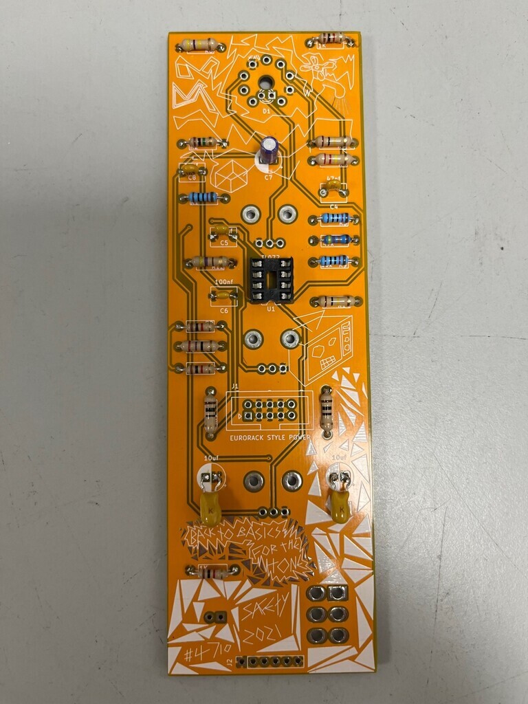 I'll have to modify this one a little bit. It uses an ECC83 dual triode which has two 6.3V heaters; one for each side of the valve. You can either wire them in parallel on a 6.3V supply or in series if you have a 12V supply. On here they're in series because the supply is +/-12V. The 6N2P Soviet version has the heaters in a different configuration and they'll only run on 6.3V as they're internally connected (as I understand it). I thought about just buying another ECC83 for this but they're £15-£20 and I just bought a load of 6N2Ps for this project. What I can do is break the power line and put a 7806 (6V regulator) inline with the heater supply. Now it's just a matter of sitting down and putting together some shopping lists for various places like Rapidonline, eBay and Thonk. |
| |
|
|
|
|
|
|
|
|
|
obviously i checked in the loft to see if i had a 24k resistor and i did and then i spent the whole night awake sweating like i had Covid and then i had no choice but to change that resistor to the 24k  The little LED readout arrived in the post. I was kicking myself about this because I threw a whole load of these out when I consolidated my electronics collection, thinking I'd never use them, but this one is only about 2/3 the size of the ones I had. It goes in here like this: 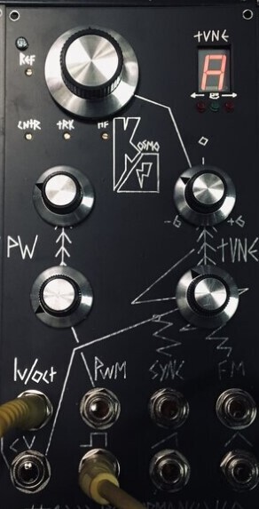 That obviously got me thinking, what if I had another way of doing the readout, one which would be harder to read, would be harder to wire up and cost me more and/or not work properly? Bingo:  Maybe one for later once it's working. |
| |
|
|
|
|
|
|
|
I've been putting off doing this, but I got stuck in at lunchtime and temporarily swapped the transformers over. First, some pics of the existing wiring layout so I don't forget...  Then I could take them off. Size comparison between the two transformers:  And fitted:  So it’s a bit fugly, but it’s just a temporary swap to see what they sound like. I've not played any music through it yet, but the scope says quite a lot more hum gets through. I was irritated by this at first, but actually it's probably to be expected. The bigger transformers will let more low frequency through so of course they will let more residual 50hz hum pass through too. I’m planning a new build for these because I quite like the small format of this amp and want to keep it as it is, so the new one will need a bit more careful thought about hum suppression e.g. wire routing, using the smoothing choke, tying the heater to the HT etc. |
| |
Last Edit: Jul 12, 2023 17:22:46 GMT by Jonny69
|
|
jimi
Club Retro Rides Member
Posts: 1,816  Member is Online
|
|
|
|
Your post above reminded me about these displays that I rediscovered in a box. I bought them years ago for a led rear light project that I abandoned because I went a different route.   Roughly 52mm x 38mm I have 8 of them, if they are of any use to you you can have them. I'll never use them so they are better going to someone who will use them. Apologies for the thread distraction 🤭 |
| |
Black is not a colour ! .... Its the absence of colour
|
|
|
|
|
|
|
|
This is cool. My head doesn't do Electrics very well but I love electronic music and hearing sounds I havnt heard before, so I tend to listen to alot of weird music.looking forward to hearing what this chucks out.
|
| |
Last Edit: Feb 10, 2023 0:08:35 GMT by bmcnut
|
|
|
|
|
|
|
Roughly 52mm x 38mm I have 8 of them, if they are of any use to you you can have them. I'll never use them so they are better going to someone who will use them. Apologies for the thread distraction 🤭 Aahhhh, they’re quite tempting. I’m thinking at some point I’ll have a crack at making a basic octal counter sequencer and these would look cool counting along if there’s 8 of them. Some way off doing that at the moment though! Can you hold onto them? |
| |
|
|
|
|
|
Feb 10, 2023 10:20:00 GMT
|
|
Ran it for about an hour last night. No shortage of bass now. Version 2 is gonna be gooooood.
Interestingly, it runs way cooler. The output transformers don't get hot at all, whereas the little ones cook. And the power transformer doesn't seem to get as hot. Been discussing why this might be with a pal. I'd initially assumed that the heat from the small transformers came from the HT current going through them, but maybe it's not that. I'd wondered if the DC resistance was lower on those than these new bigger ones, despite the same 5k Ohm impedance, and that the heat was coming from the higher HT current. My pal on the other hand thinks it's probably losses in the transformers. This kind of makes sense. I'm actually driving the new transformers with no bass boost and getting more bass out, so I'm putting less in and getting more out from that perspective. I had assumed that the low frequencies simply get blocked, but it might actually be getting absorbed by the transformer cores.
|
| |
|
|
|
|
|
Feb 10, 2023 16:48:41 GMT
|
Small modification needed for the Safety Valve module because I'm using a 6N2P instead of an ECC83. The ECC83 has two separate heaters; one for each triode half. You can wire them independently; they are in series from pins 4 to 5 and the midpoint is on pin 9. So you can run them on 12V if they're in series. On the 6N2P, both heaters are wired in parallel between pins 4 and 5 and pin 9 is just a shield. It can therefore only be run on 6V. The Safety Valve has the ECC83 heaters in series. I plan to put a 6V regulator inline so I can use the 6N2P. Tracing the heater pins back, one side is grounded and the other goes back to the -12V on the power connector, as marked:  My 7806 regulators are +ve regulators, not -ve, so I'll have to switch that to the +12V rail. I'm going to solder wires straight to the pins. This is a convenient place to put the 7806, where it's not in the way of any of the other components yet to go on and the legs are high enough that they won't make contact with those PCB connections:  Up at the top, I need to drill out the hole where the +ve heater pin goes through so it no longer makes contact:  And then add some wires:  Job done. Well not quite. When I tested it the valve did not light. Odd. Tested the voltages and everything was getting through, but then I realised I'd soldered the valve on the wrong side of the board. Balls. And I couldn't get it back out because the board has through-hole solder connections because it's double-sided. I resorted to clipping the legs in the hope that I'd be able to solder onto the stumps, but the valve popped on the second leg. This is why you should always use IC holders and valve holders. Lesson learned. |
| |
|
|
|
|
|
Feb 10, 2023 17:36:01 GMT
|
|
It's always the component with them most legs/ most fragile/ prone to heat damage that you solder in the wrong way...
Nice work though!
|
| |
|
|
jimi
Club Retro Rides Member
Posts: 1,816
Member is Online
|
|
Feb 10, 2023 21:07:46 GMT
|
Aahhhh, they’re quite tempting. I’m thinking at some point I’ll have a crack at making a basic octal counter sequencer and these would look cool counting along if there’s 8 of them. Some way off doing that at the moment though! Can you hold onto them? I don't want anything for them 😉 PM me your address and I'll post them to you  I wasn't going to dump them, but they may disappear back into the black hole that is the abandoned projects box 🤣 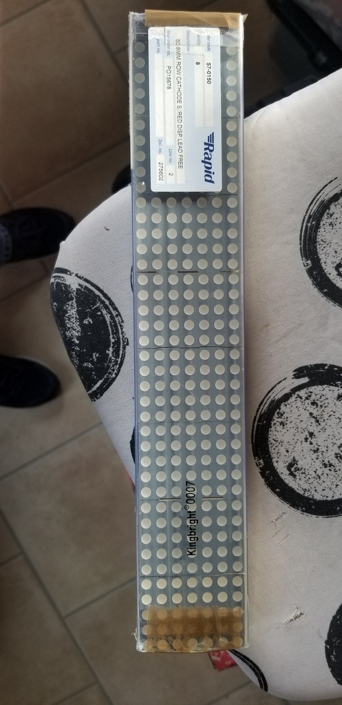 |
| |
Last Edit: Feb 11, 2023 20:25:45 GMT by jimi
Black is not a colour ! .... Its the absence of colour
|
|
|
|
|
|
|
Feb 11, 2023 11:12:57 GMT
|
Great, will drop you a line about those jimi. Brain now in overdrive planning out a sequencer! Delivery from Thonk has arrived. This is potentiometers, jack sockets, power cables and the CEM3340 signal generator for the oscillator. I have almost everything I need to get it running now, bar a holder for the Arduino and a couple of capacitors.  |
| |
|
|
|
|
|
|
|
|
|
| |
Proton Jumbuck-deceased :-(
2005 Kia Sorento the parts hauling heap
V8 Humber Hawk
1948 Standard12 pickup SOLD
1953 Pop build (wifey's BIVA build).
|
|
|
|
|
Feb 12, 2023 18:22:19 GMT
|
That was an interesting read, thanks for that. |
| |
|
|
|
|
|
Feb 13, 2023 15:38:24 GMT
|
Bit more progress at lunchtime. I got the pots and jack sockets soldered on, plus a few last little bits like the display and LEDs. It's just the Arduino holder missing now, I think, so once that's on I can power it up and start to calibrate it. So, first view:  I soldered my display and LEDs flush with the front because I thought it would look better than the display being well below the surface and the LEDs sticking out. Personal preference. Slightly annoyed that I didn't notice my display was white and not black when I ordered it. Oh well.   Will also need to do a bit of cleaning to get all that flux off. I think there's probably almost as much in my lungs. |
| |
|
|
|
|
|
Feb 15, 2023 17:30:45 GMT
|
Got the Arduino coded up yesterday and soldered the final chip holder in so it could mount up. Then, technically it was complete and ready to go. I'd kind-of thought about power but not really thought about power. This uses standard Eurorack power connections which are a 16-pin connector on a bus board going to a 10-pin connector with +12V on one end, 0V in the middle and -12V at the other end:  Pinched that pic from here: division-6.com/learn/eurorack-power/I needed to cobble something up to go on my bench supply so I made up a little board with header pins that the ribbon connector can go on:  That got me power, but no output and the CEM3340 was getting rather hot. Because I'd put it in the wrong way round. That's what chip holders are for. Once corrected, I could see waveforms on the scope. Hooray! Ideally, I also needed some way of connecting up to speakers as well, so I soldered on those purple leads so I could bodge it through a 3.5mm socket. Once I could hear things, I could then tune it up following the video in the build instructions. I did it to C like he did, but just did it by ear and it's close enough for me!  So. There are a couple of things I need to buy and build before I can progress: - I need quite a few 1/4" jack leads (everything connects with these), some bare plugs I can put flying leads in (for testing) and a reducer or two to 3.5mm plugs
- Build a rudimentary case
- Make some kind of output panel
For point 3, I need to reduce the output down to line level so I can plug it into an amp. I could just use a potentiometer, probably/maybe, but I think then connecting the volume control from the amp might make it go screwy, so I'm going to reduce the level with an op amp with a 'gain' of like 0.1 or something. The output looked about 12V with the square wave and a bit lower for the ramp and triangle. If I use an op amp to reduce it, it effectively isolates the input and output and the volume pot on the amp won't interfere with it. Tomorrow: back to school on inverting amplifiers. Where was that random website I used in the other thread? |
| |
Last Edit: Feb 15, 2023 17:33:27 GMT by Jonny69
|
|
16grit
Part of things

Posts: 213
|
|
Feb 15, 2023 18:36:28 GMT
|
|
Onboard for this one.
I have a few boxes of obscure NOS 70s/80s/90 ICs and other bits and bobs so if you are ever after something weird shoot me a number and i'll take a look.
Your thread has reminded me to check in on this guy, he's made some progress before I last took a look...
|
| |
Last Edit: Feb 15, 2023 20:05:53 GMT by 16grit
|
|
|
|
|
|
|
|
^ That guy has done some crazy projects in the past. Way beyond my knowledge of valves!
Cheers for the offer - you just reminded me I haven’t messaged jimi about those LED panels…
|
| |
|
|
|
|
|
Feb 16, 2023 12:03:35 GMT
|
Pretty sure I know what I want to do with the output panel. I reckon a 50mm wide panel sprayed satin black should do the trick. On there will be (top to bottom): -1/4" jack socket input -Volume knob (but do I need this?) -3.5mm socket output -2x RCA outputs That won't take up the full panel and I'm going to deliberately leave the bottom half unpopulated so I can add a high level output to directly attach a speaker to. I'll put a small amp on the back like 2-3W that can run on the main +/-12V supply. For the low level outputs I need to reduce the main synth output from 12V peak-to-peak for the square wave to around 0.5V. That means a 'gain' of 0.5/12 = 0.04 approx. I'd also like to keep the phase the same so that the sawtooth waves stay the same way up. I can't use an op amp in non-inverting mode because of the way the gain works:   (images pinched from that site again) In non-inverting mode the gain has to be higher than 1. In inverting mode however: 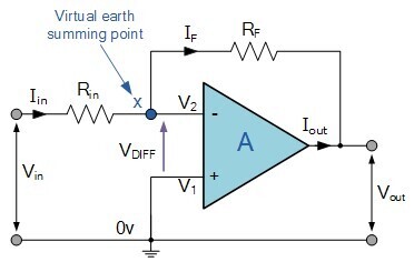  So if Rf is smaller than Rin, it should reduce the voltage by whatever that ratio is. In my case they need to be a ratio of 1:24 approximately so like 10k and 240k or something. It would be quite easy to put a preset pot in series with Rf to add in additional resistance if the 0.5V is too low. The waveform is inverted, since it's an inverting amplifier, so to flip it over the right way I'll run it through a second inverting op amp with again of 1 (where Rf and Rin are equal). All my op amp chips are doubles or quads, so there will be a spare to do this. |
| |
|
|
|
|
|
Feb 16, 2023 18:34:27 GMT
|
Quick proof of concept after work. Treated myself to a quick bit of breadboarding:  With the resistors at 10k and 220k and the inverting input plugged into the +12V rail, I got -0.556V out. Swapped the 10k to 22k and got -1.2V out. So that’s working a treat. Since I’m planning to have a volume control on it, I might just go for that 10:1 reduction and keep the circuit simple. |
| |
|
|
|
|
|
Feb 20, 2023 14:36:49 GMT
|
I made a start on the input/output (IO) panel.  -1/4" jack socket input at top -Volume knob -3.5mm socket output -2x RCA outputs -High level output for direct to a speaker (mono)  Front of the panel will be satin black. On the back is a small Veroboard which will house the op amp voltage reducer. I don't currently have an audio amplifier in mind for the high level output, but that can wait until later (actually, I have some completely random L165 3A power op amps which will probably do the trick for the needs of this. Nothing to lose). |
| |
|
|
|
|


