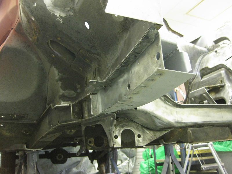
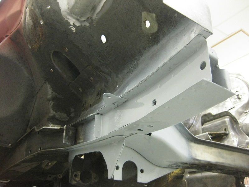
|
|
|
|
|
We´ve got quite a few subjects covered here in the usefull threads department but the most important one is missing ;D How to make panels.... What we need is a metalwork thread where we can all meet up and either help each other out or just ask lots of questions. Now there´s loads of fantastic posts in "Readers rides" and as soon as i find them all again i´ll add them to the thread. Although i feel quite comfy branding an anglegrinder and am more than happy to show anyone how i dodge stuff together there are one or two very talented people on here that are in a different league. After following tonybmw´s masterclass in panelbeating he´s very kindly offered his support for this thread. I´ll copy over some of his posts to get us started but please feel free to add your own wisdom and or questions so that we can get as much information together in one thread as possible. Comments, feedback, questions, alternatives all greatly welcome but lets keep it on subject please METALWORK - & WELDING ONLY PLEASE! ;D |
| |
|
|
|
|
|
|
|
|
|
...and this is where the work starts 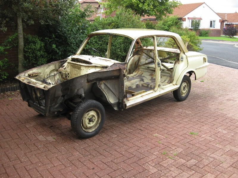 A quick jet wash even took the underseal off the inner wings so that was useful 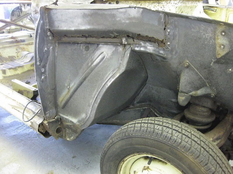 I decided to start with the inner wing repairs first as they looked the most straight forward, after a going over with the twist knot brush this is what we had 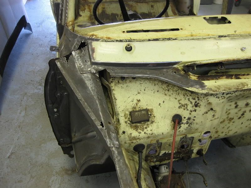 How wrong can you be, once the first layer was cut off it exposed another rotten layer, and then another, all the way back to the bulkhead 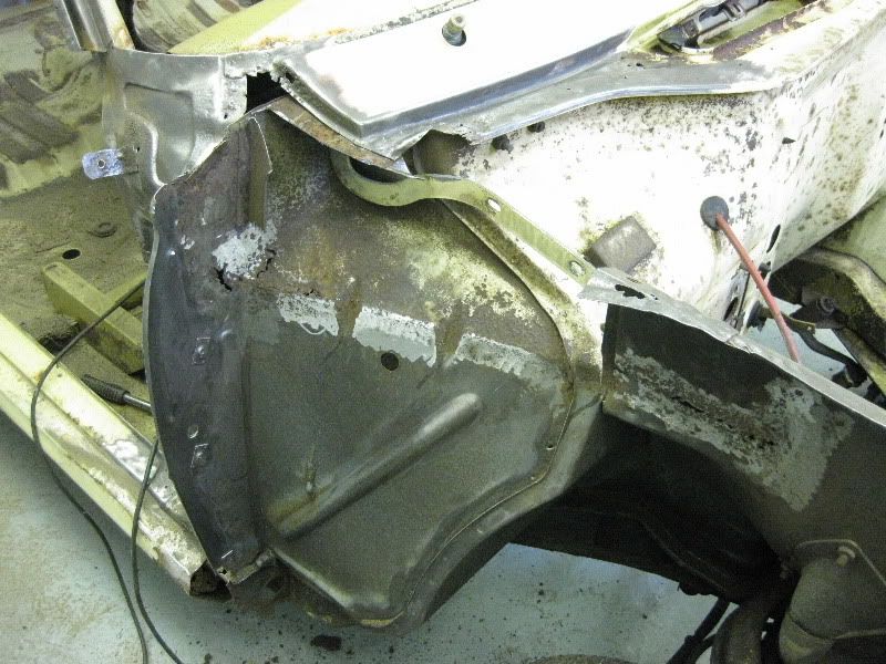 The only way to deal with this properly is to cut it right out 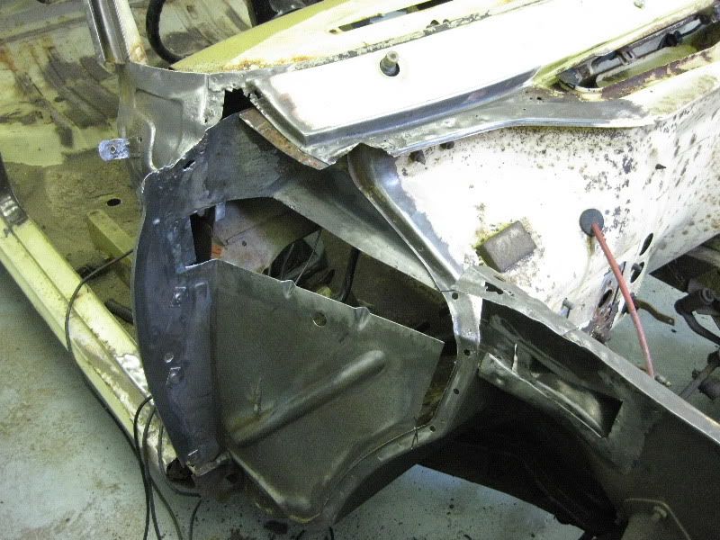 And then the patching commences 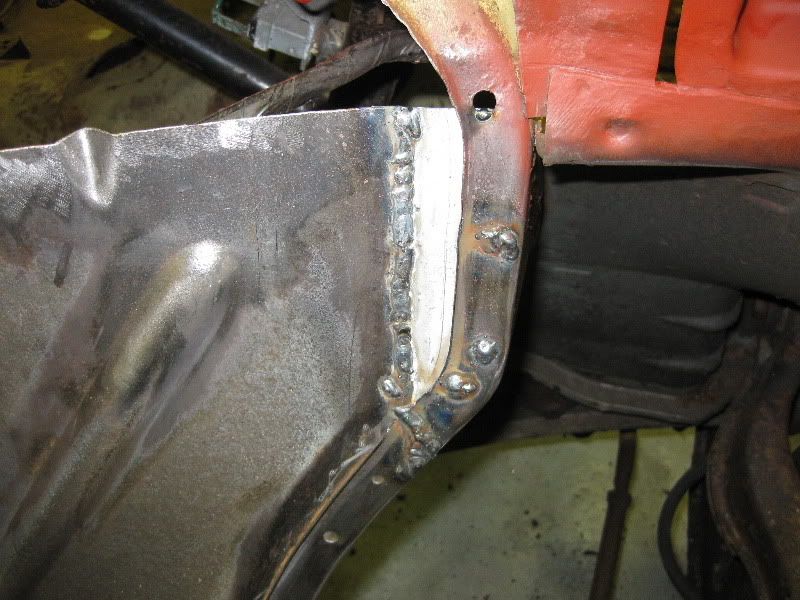 Of course there are very few repair panels available so most parts will have to be made by hand from sheet steel. Panel number 1 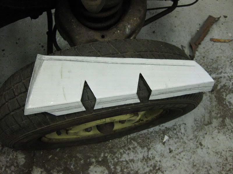 Tacked in 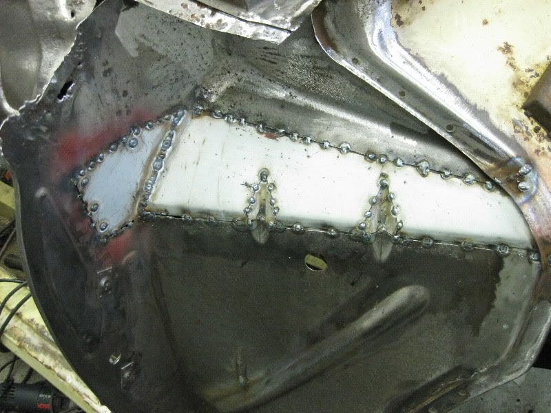 Welded in 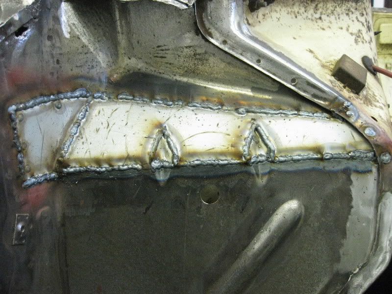 Cleaned off 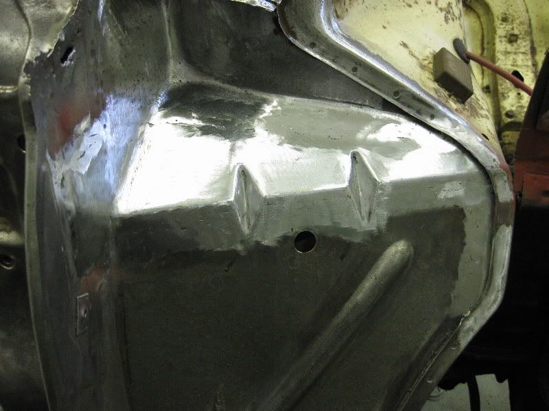 Primered 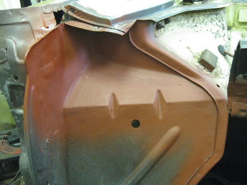 Panel 2 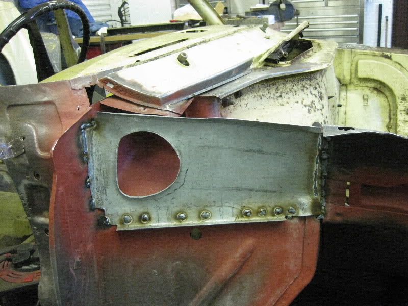 small patch 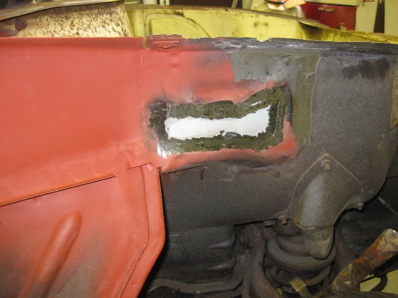 Then on with panel 3, each of these parts took a while to make so this was it for that day 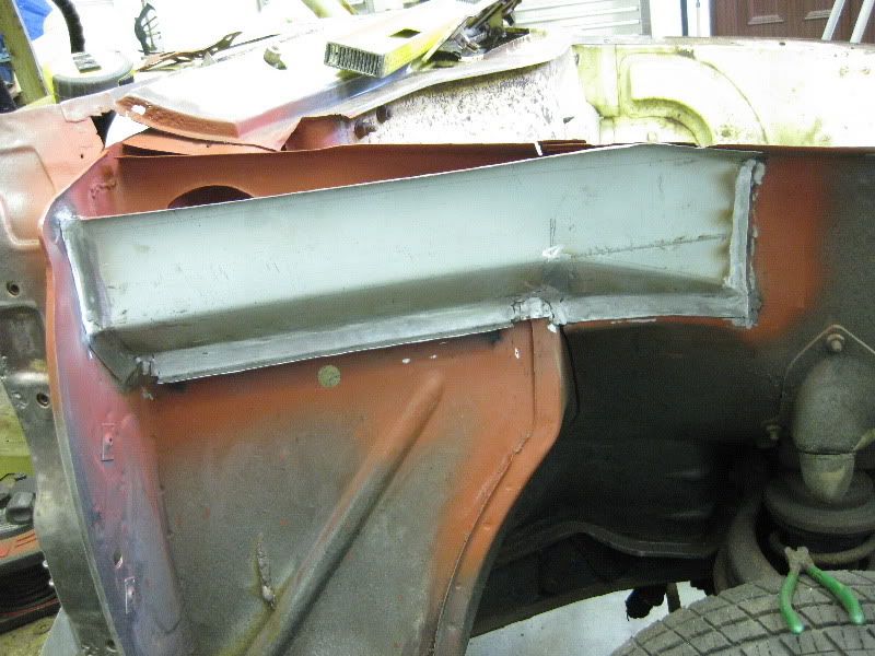 The next day saw me completing that inner wing section 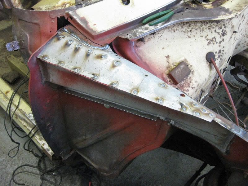 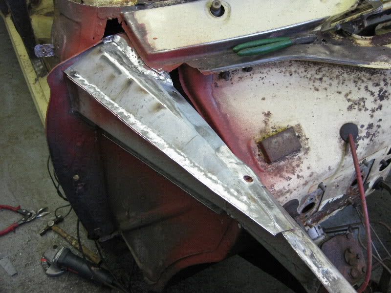 A repair then needed to the windscreen surround and scuttle area 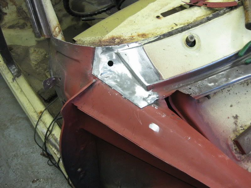 |
| |
|
|
|
|
|
|
|
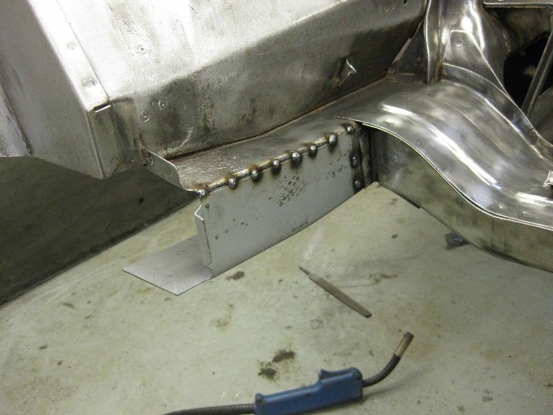
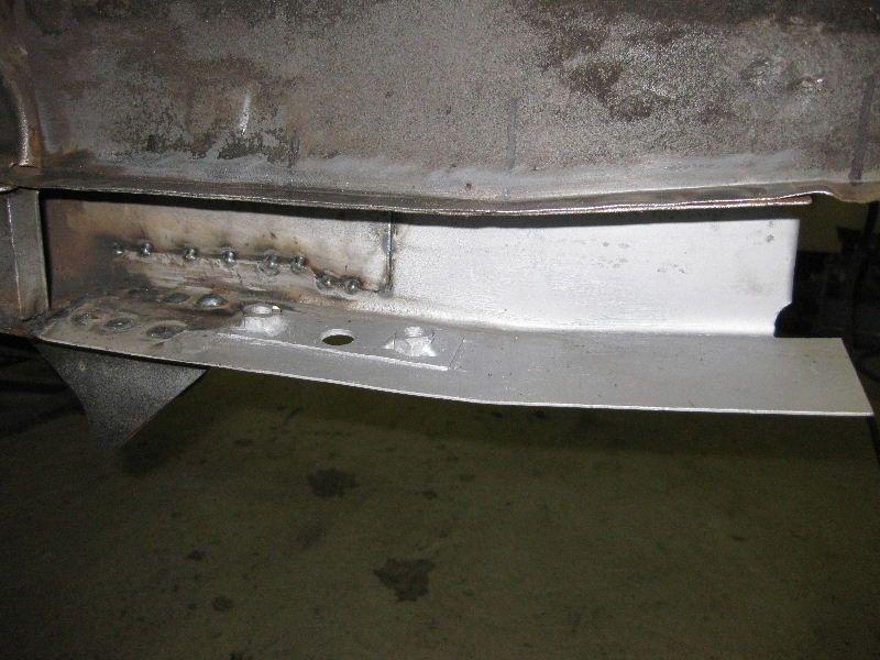
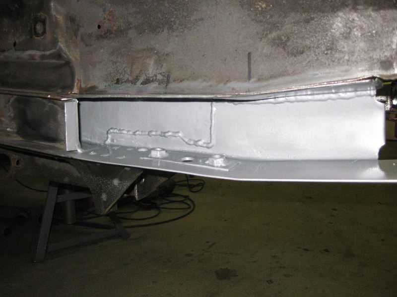
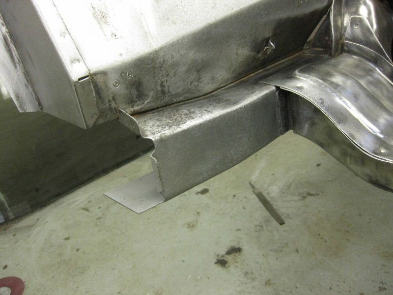
It seemed logical to stick with this side so I moved down to the door pillar and sill area, as it turned out the sills had been repaired before at the front ends, very nicely done with plenty of filler and pop rivets, looked great but not very structural. 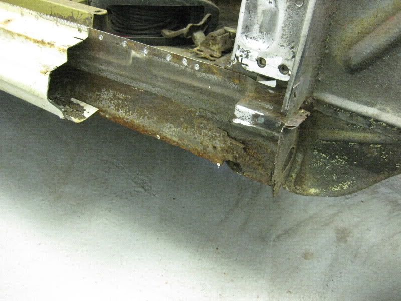 Once the rot was cut back we were left with this, I had to remove the bottom part of the pillar to remove the full sill section, Gordon had been lucky to find a genuine full sill for this side, so I wanted to use as much of it as possible, to try to replicate that factory look 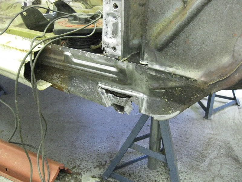 So I made up a patch for the bottom of the closing panel, apologies for not taking more pictures, (note to self : must take more pics when doing the other side) Anyway here is is, welded in cleaned up and primered, concealed wing fixing also swapped over, onto the new panel, also patch fitted by the jacking point 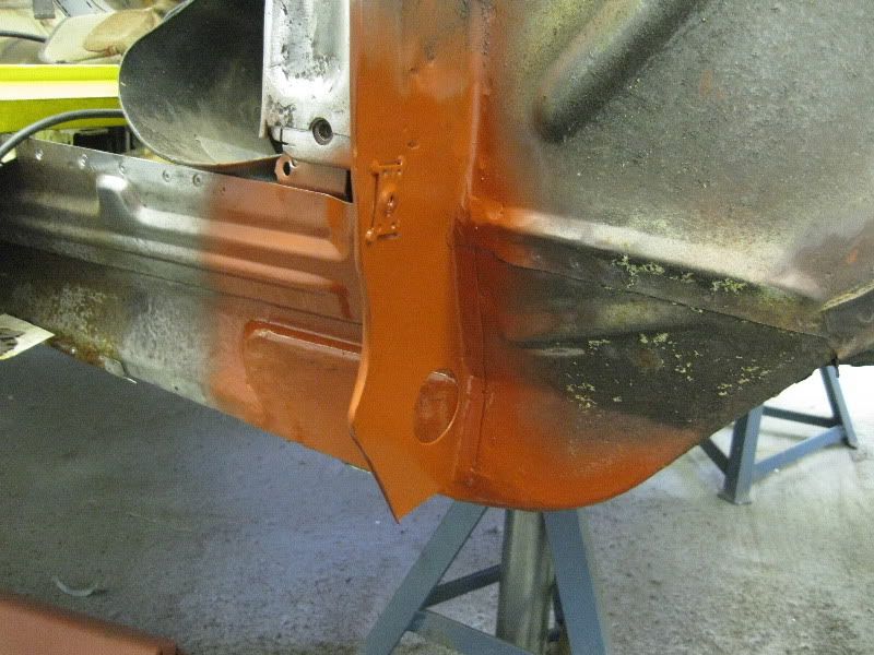 At this point a Really needed to think about getting the sill on to line everything up, so it was off with the old one 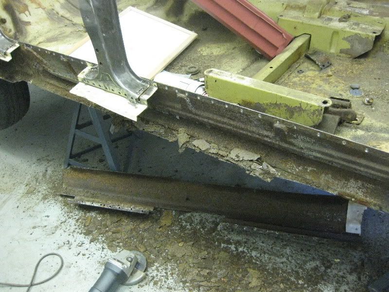 Note spot welds all drilled out, I find that if you rub the area with a piece of sandpaper on a flat block, then it is easier to identify where they are, they all need to be drilled out, to release all of the old sill. 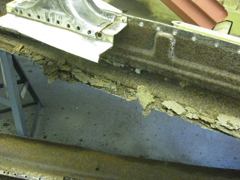 At first I thought that the inner sill was going to be okay, and it would just be a matter of cleaning it up and welding on the new sill, after all it was very clean and solid, when viewed from underneath. 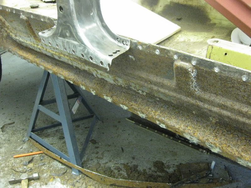 But the fact that this car had been standing so long in damp conditions meant that it was rotting from the inside out, so once I started grinding it clean, it soon became apparent that further repairs would be needed. 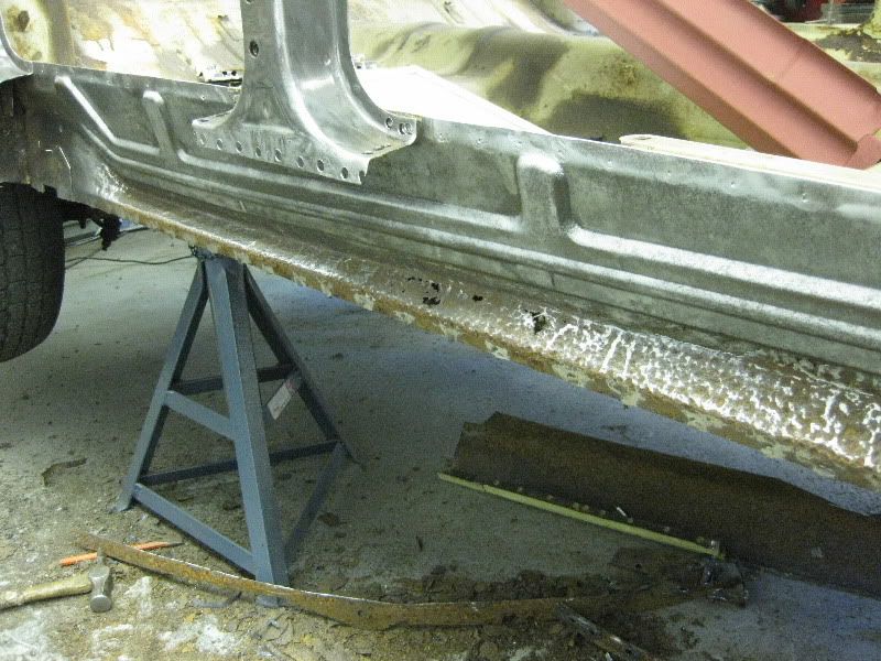 So off with the rot 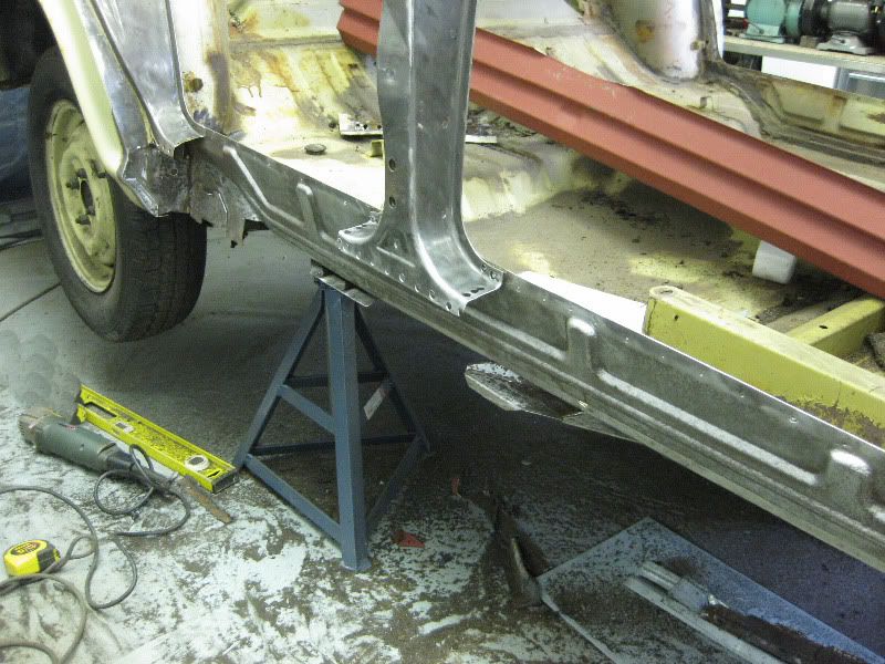 and new panels made 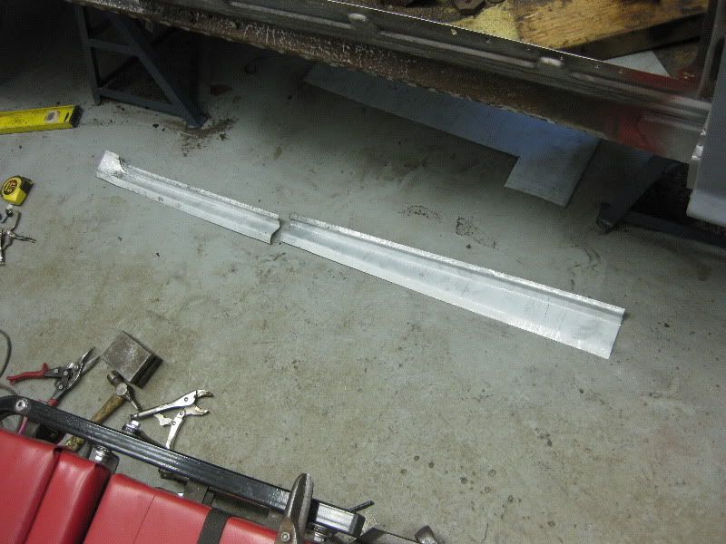 And welded into place, as I could get good access from both sides, I decided to spot weld these on, welding them to the inner sill and the floor pans for maximum strength 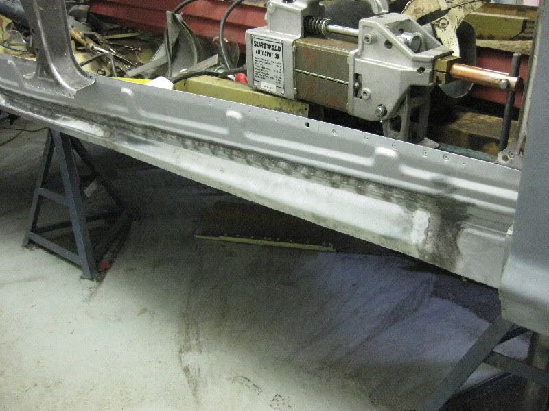 And then trial fit the sill, don't worry pop rivets are only temporary and will be removed later, honest  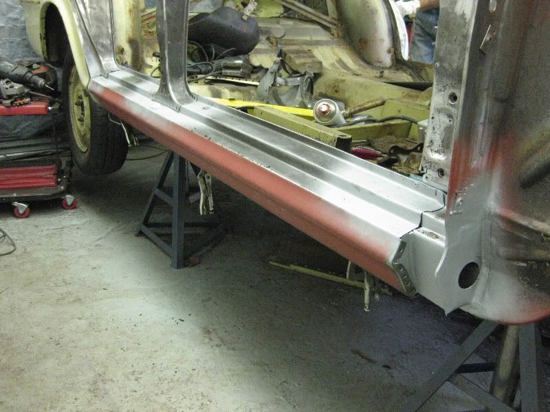 What I have not shown is the doors and wing being fitted, adjusted, adjusted again, taken off, refitted, adjusted, you get the picture. I wanted to be absolutely certain that once these sills were on, they were in the right place, with good equal and even panel gaps. I have seen far too many jobs, where the doors overlap the sills, or scrape against them every time the door opens and closes. And as my old woodwork teacher used to say, amongst other things, was " If a jobs worth doing its worth doing well" |
| |
|
|
|
|
|
|
|
Once I was happy that the sill and door gaps were good, it was time to weld it on. I am trying to replicate the factory look where possible, so the spot welder was used where possible, and the posts were pool welded in place to be cleaned off later You may remember that some of the spot welds had been near the edge of the post, so I had to use a copper block against the edge of the panel, to prevent the weld spreading out over, hence the corner welds are a little lumpy, but once cleaned up it should be fine 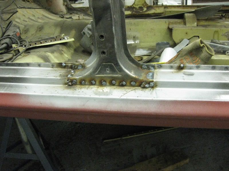 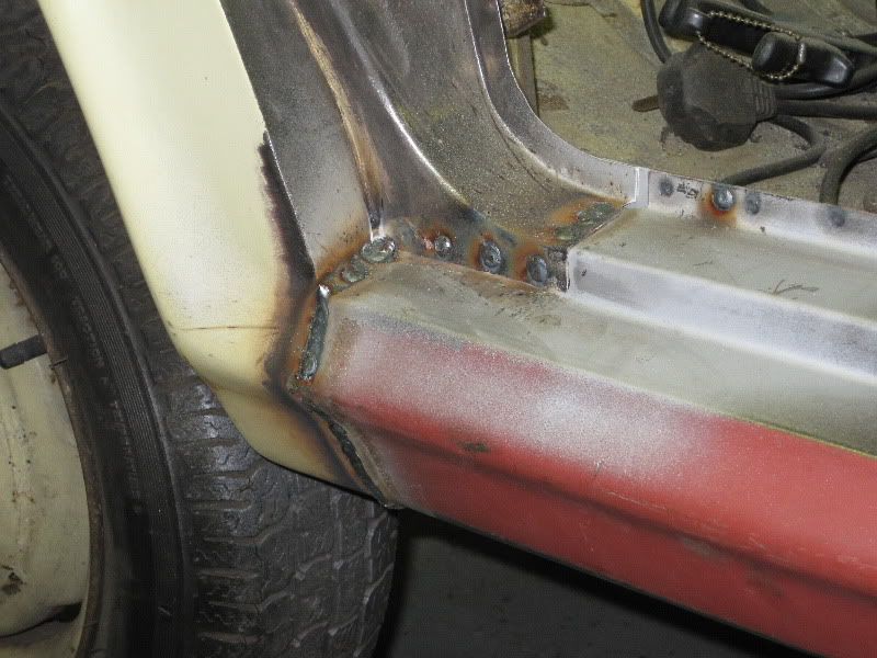 Then they were cleaned off with a 40 grit flap disc, and then a Roloc scotchbrite disc and then finally a DA sander with an 80 grit disc 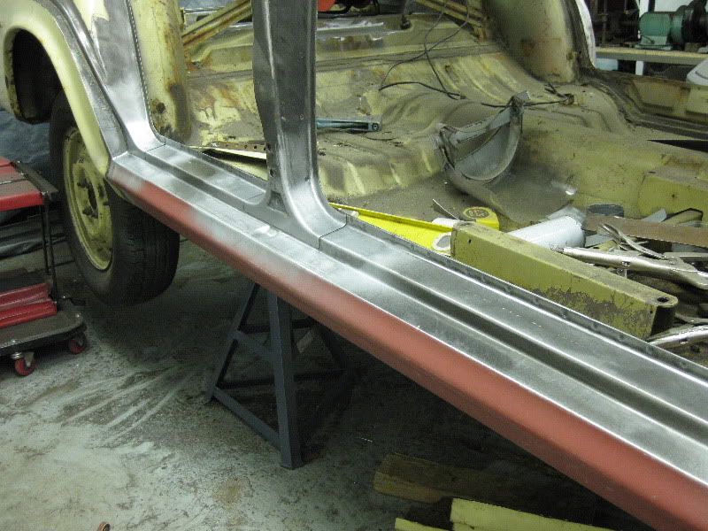 Pretty happy with them I must say 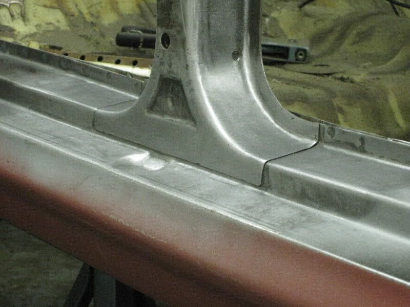 I had to use a Dremmel to get into the corner weld at the rear, if you have never used one of these, then I do recomend that you do, I have to admit that I thought they would be a mickey mouse type of tool, but their not 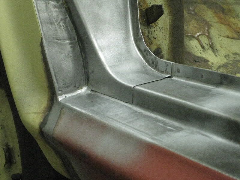 Then a quick coat of etch primer to stop it rusting 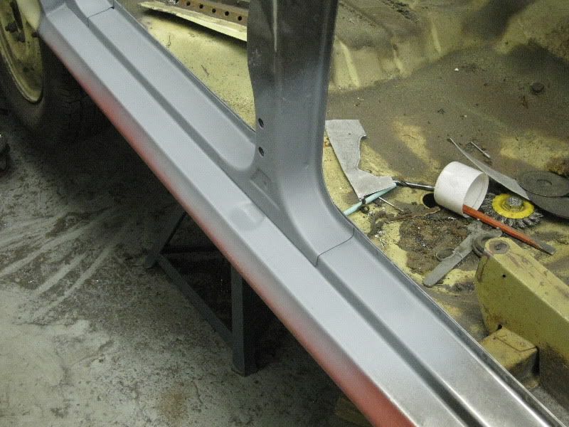 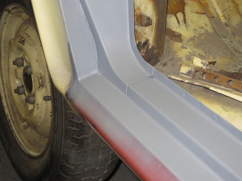 The seams were looking good from underneath too, once seam sealed and painted it should look factory fresh 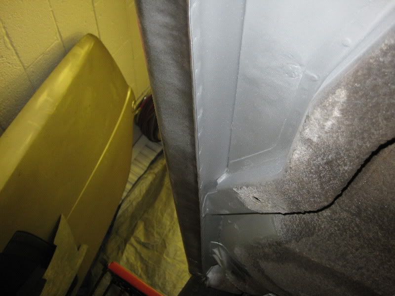 Meanwhile Gordon was busy stripping the paint in the boot, I set him away with a clean and strip disc on a drill 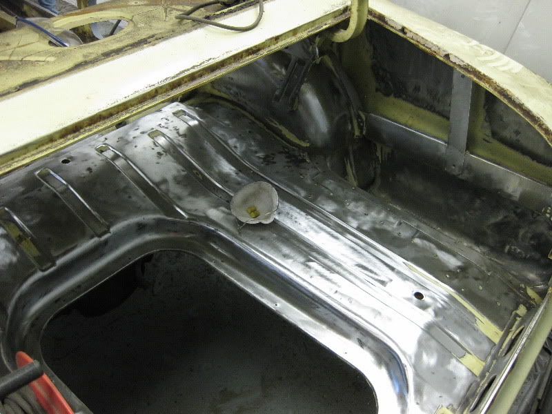 I was just tacking the front pillar back together when I ran out of welding wire, and that now brings us up to date, so progress will be slower now, only the odd night time and weekend 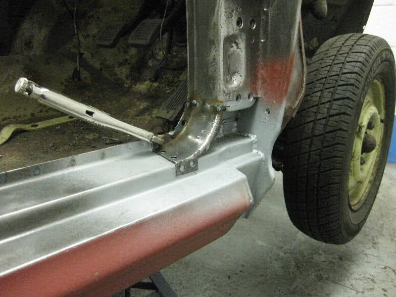 |
| |
|
|
|
|
|
|
|
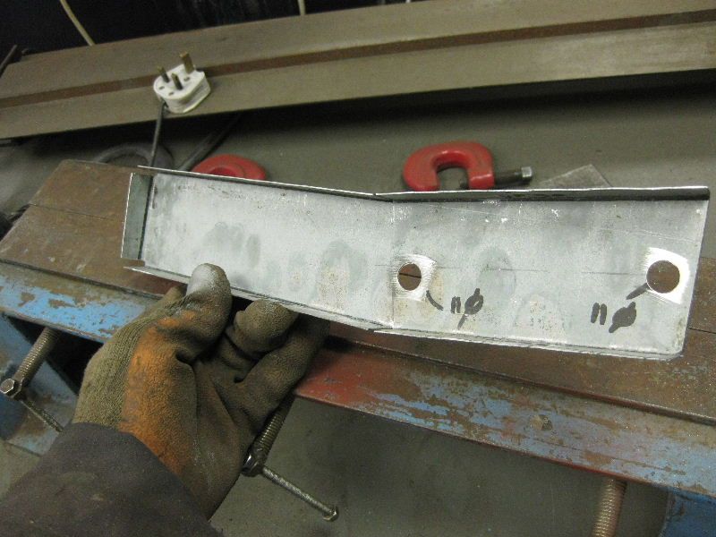
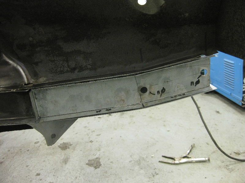
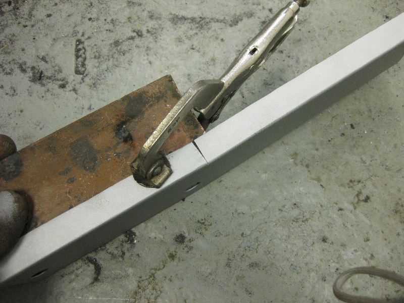
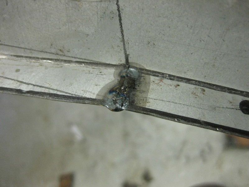
Here goes copying some of the relevant stuff over, I have tried to edit some of it to make it less specific about the Victor project if you are reading this in isolation, but you can always read the Victor rebuild if it helps You need to use a copper plate to stop the weld extending past the joint, which would then make it difficult to blend in 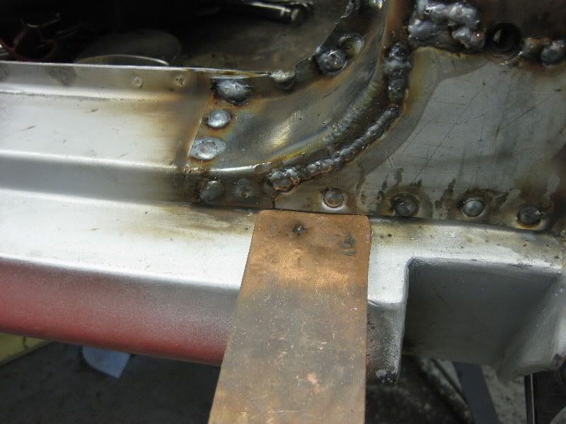 Then weld down to the copper, the steel weld wont stick to the copper 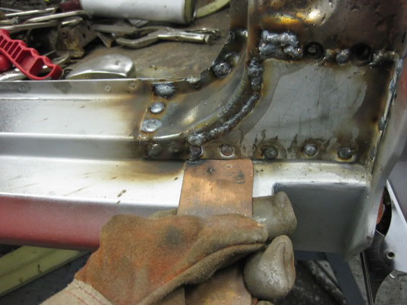 So when you pull it away, the weld has stopped just where you want it 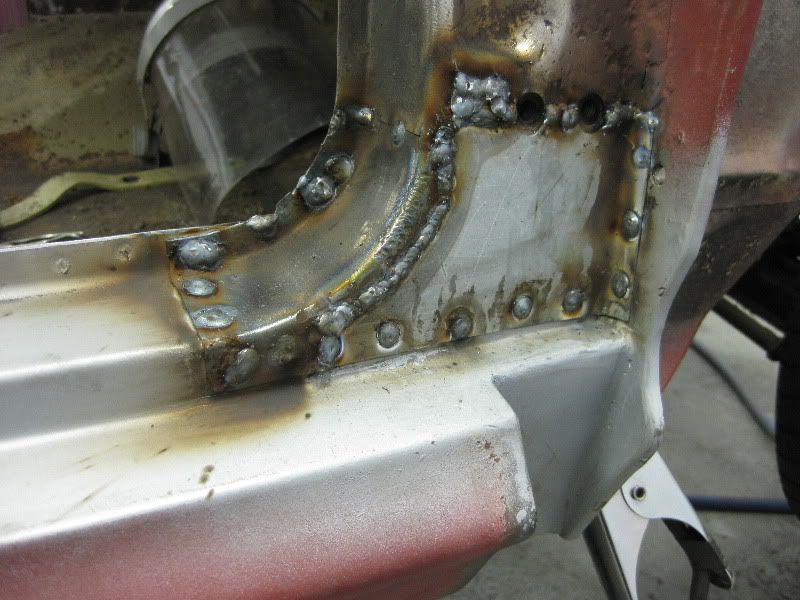 Then clean off, same as before 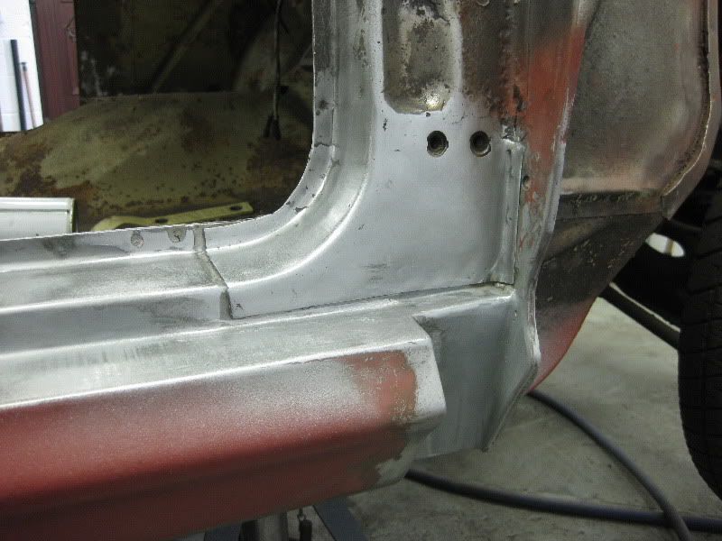 Then a coat of etch primer to finish it off 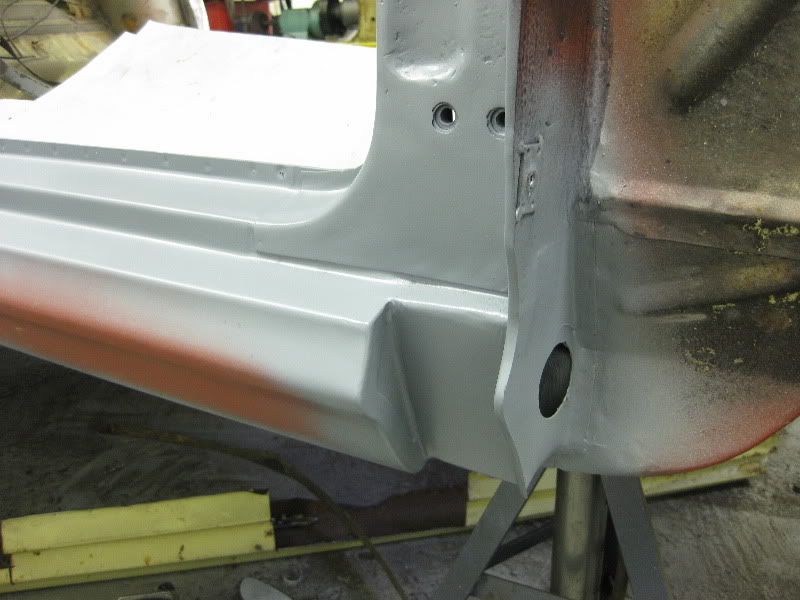 |
| |
Last Edit: Nov 5, 2009 19:46:32 GMT by tonybmw
|
|
|
|
|
|
|
This is what we are trying to make 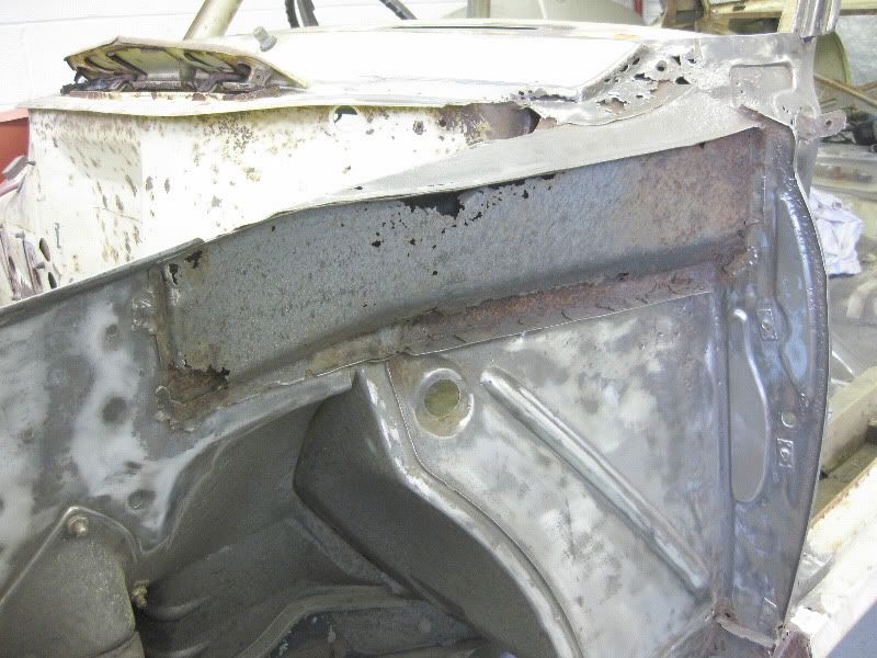 This is what I start with, a peice 1mm Mild steel Zintec sheet. 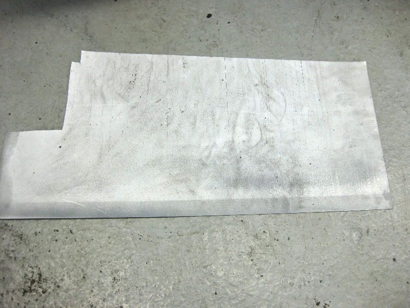 Then measure the panel 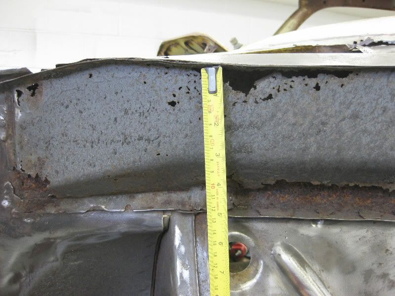 and transfer the sizes to the new steel 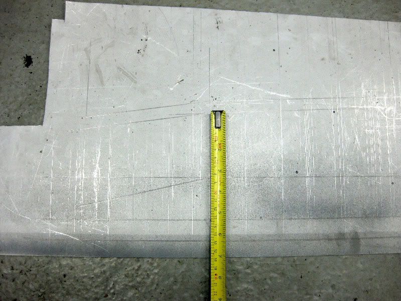 and we get this, bend lines also transfered and marked so I fold it up right later 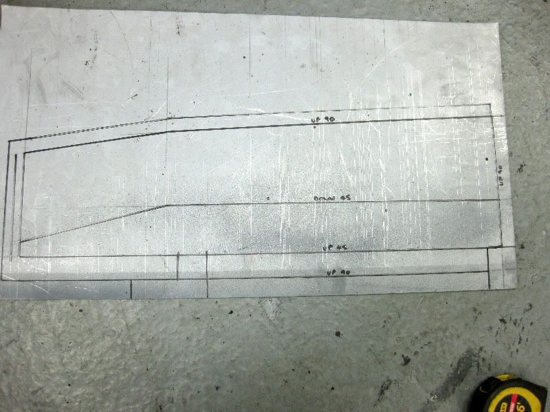 Then cut it out, I generally just use a good quality pair of Gilbow shears for most of my cutting out , although I am hopeing for a nice throatless bench shear for Christmas  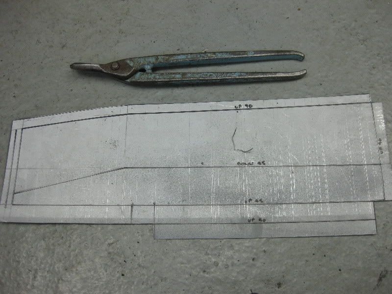 I use 2 types of bender, the first is one I bought from Machine Mart or somewhere like that, it is ok, does not do tight bends, but they are even and fine for these type of repair panels 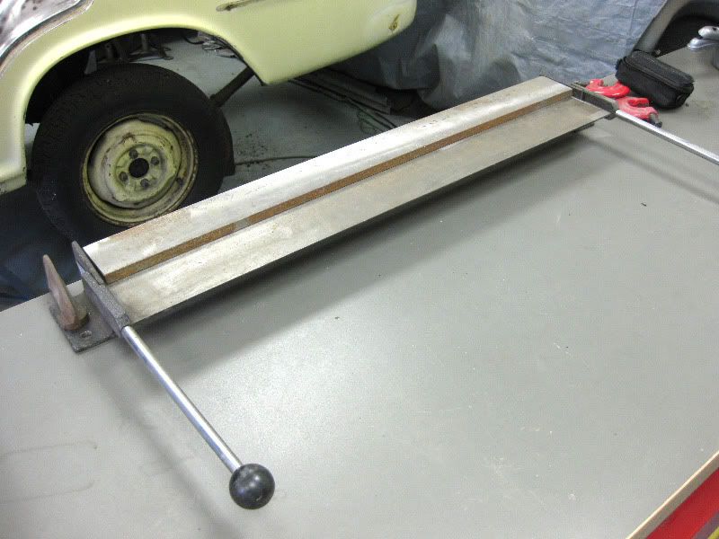 The second is home made, I made this about 20 years ago, and I have used it on every job I have ever done since then, it is a simple design, that basically just clamps 2 peices of angle together, to then allow you to tap it over with a hammer. It also doubles as a small work bench and anvil type thingy. This has been a godsend over the years, and as it is portable it goes to every job with me 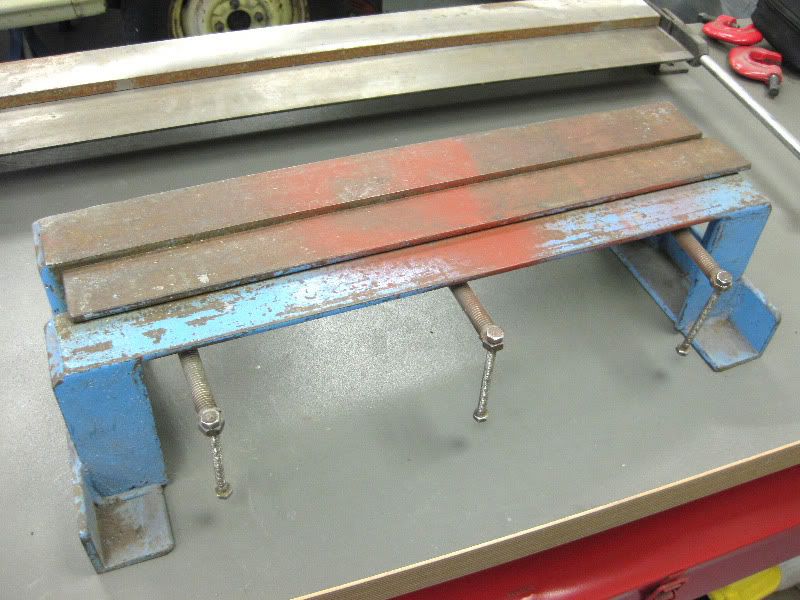 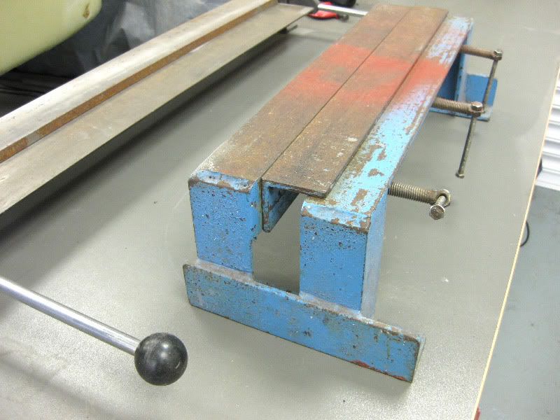 I moved the loose angle in this shot so that you can see how it works 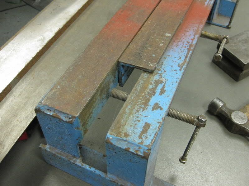 As the bends are straight forward it was into the MM folder, using the fold lines earlier marked to line it up 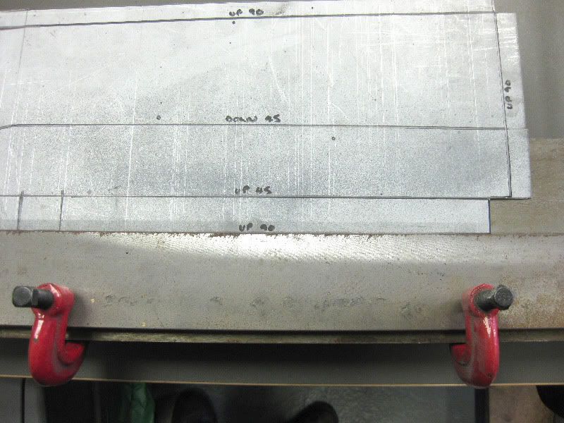 and that gave this 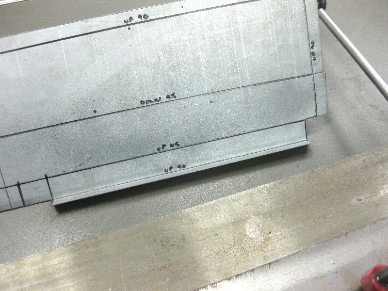 Then spin it round and put it in again, you have to think through the sequence of bends to ensure that you can always access the bend you need to create 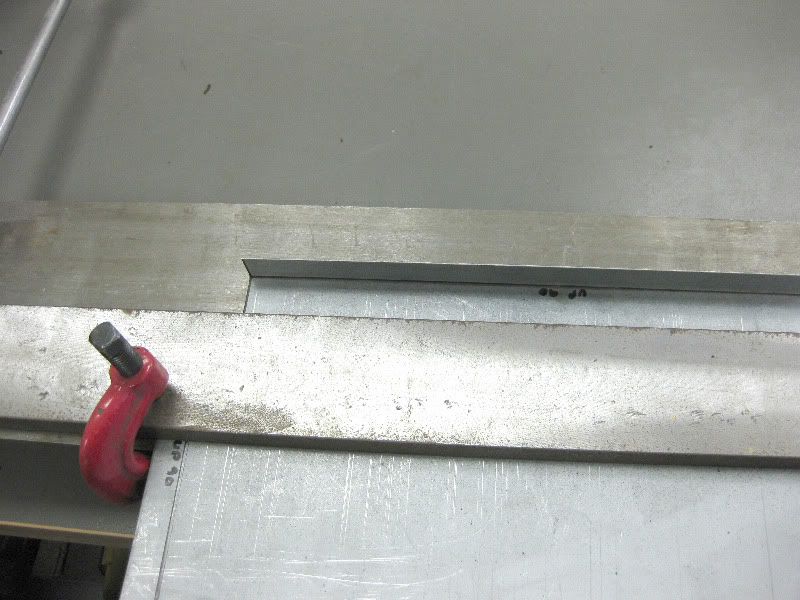 and you get this, up 45 degrees 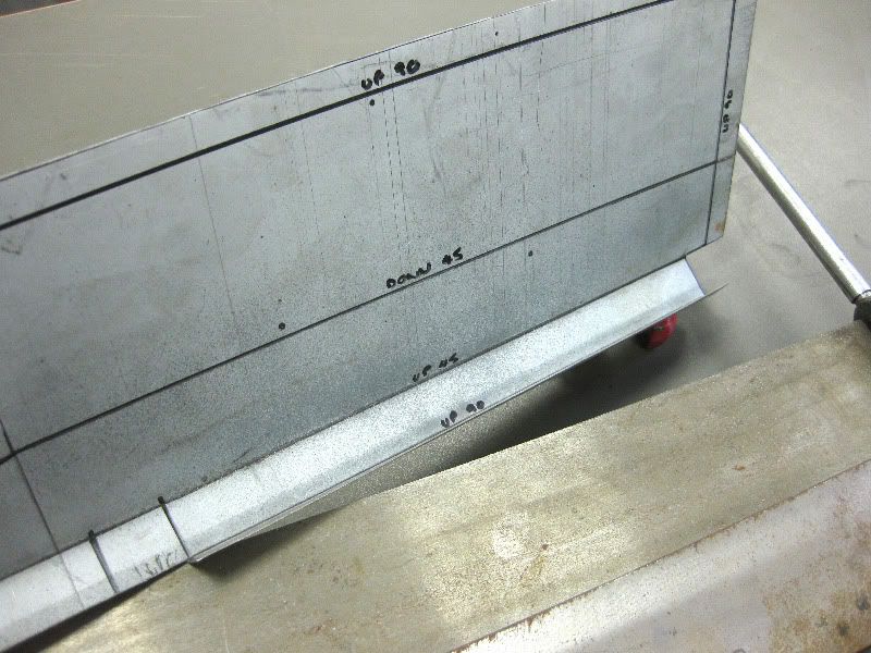 Next bends would not fit into the MM bender so the HM one was used. 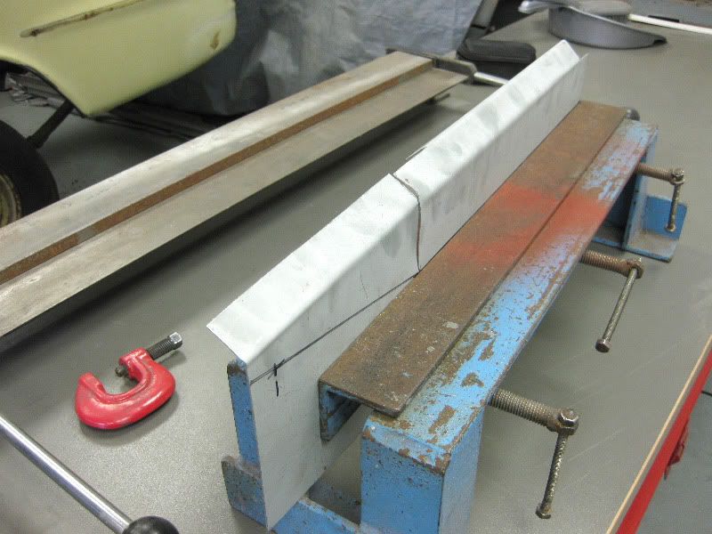 And then folded over, with large peices like this you can normally just push it over with your hands. 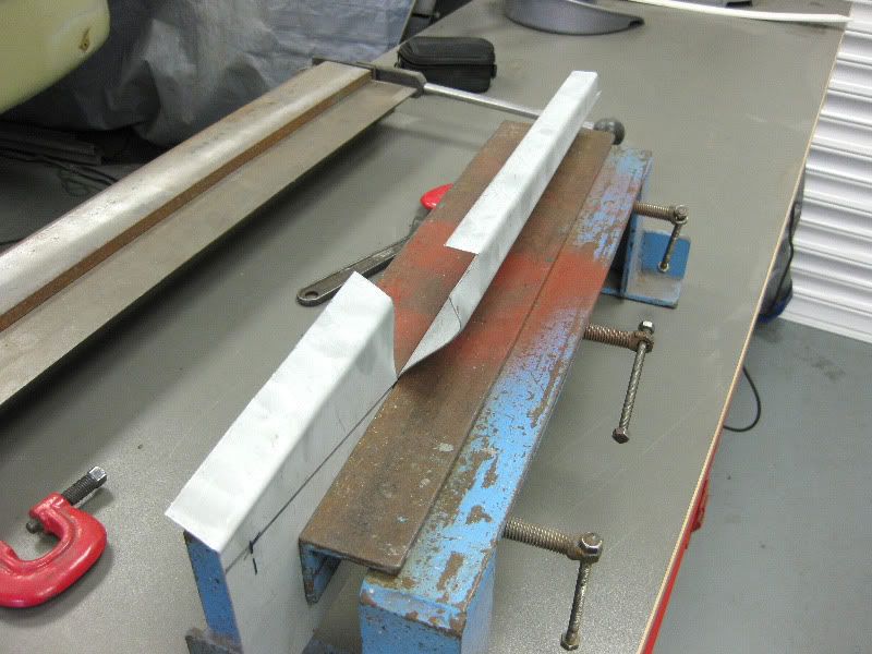 and then rearrange as needed 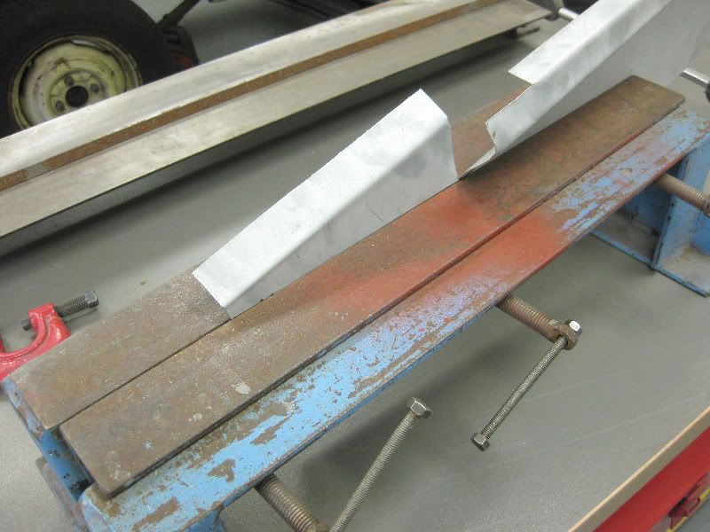 This was a bit tighter at the end so needed dressing over with the hammer. 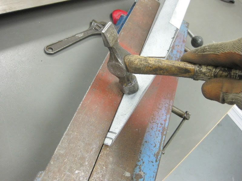 That gives us this 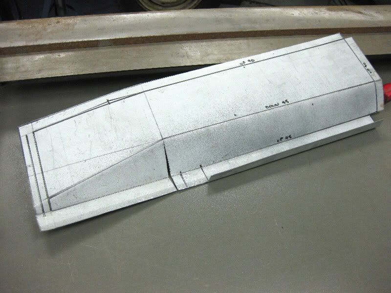 Then back into the bender 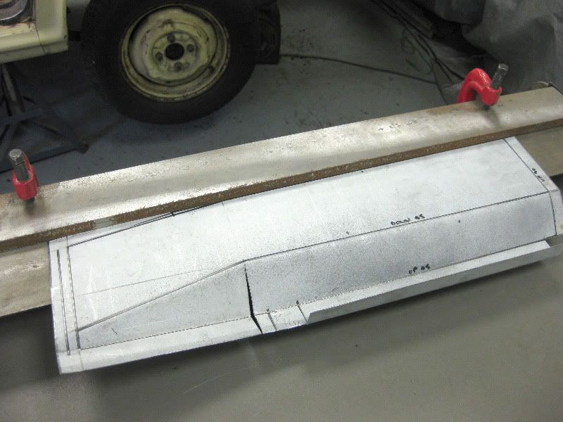 Then up 90 degrees 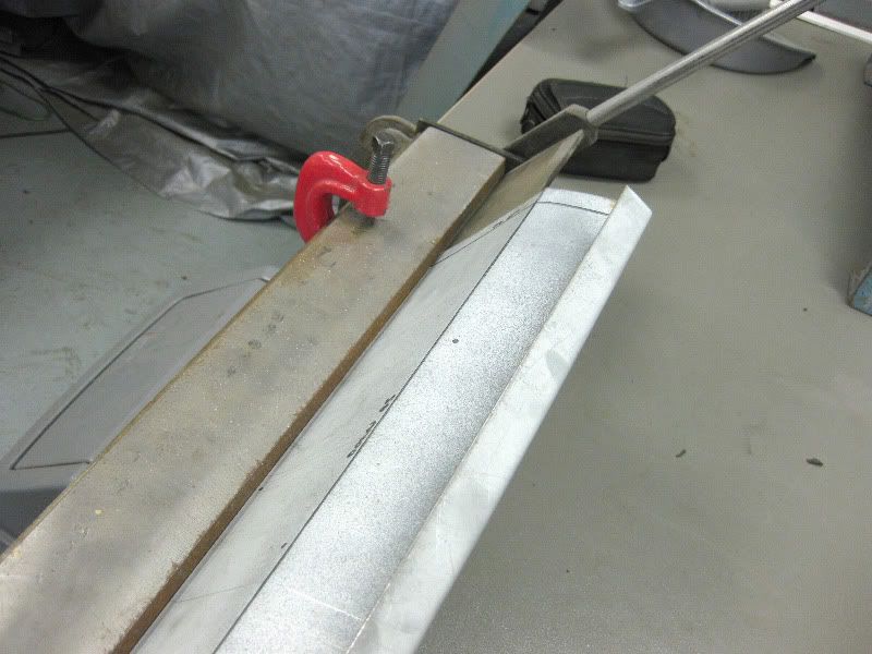 to this 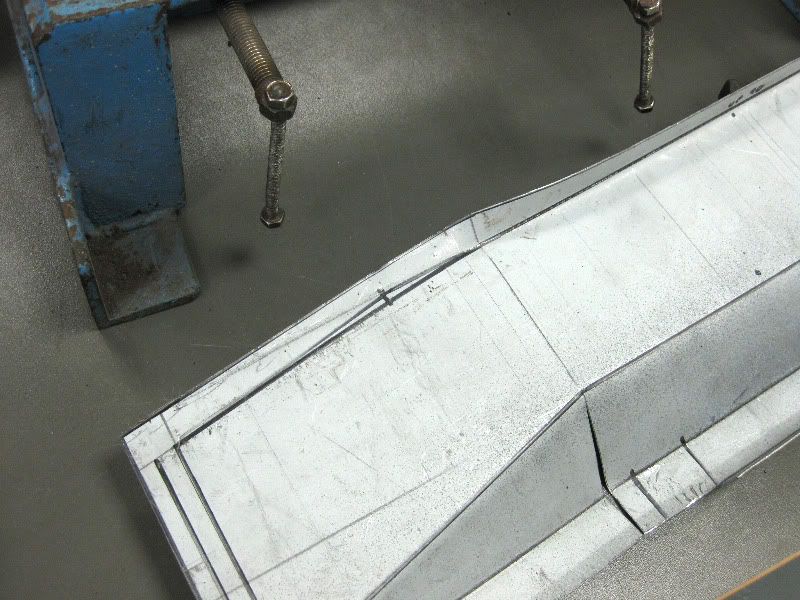 Then into the other bender 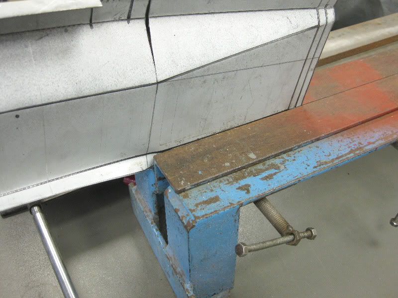 and dress over 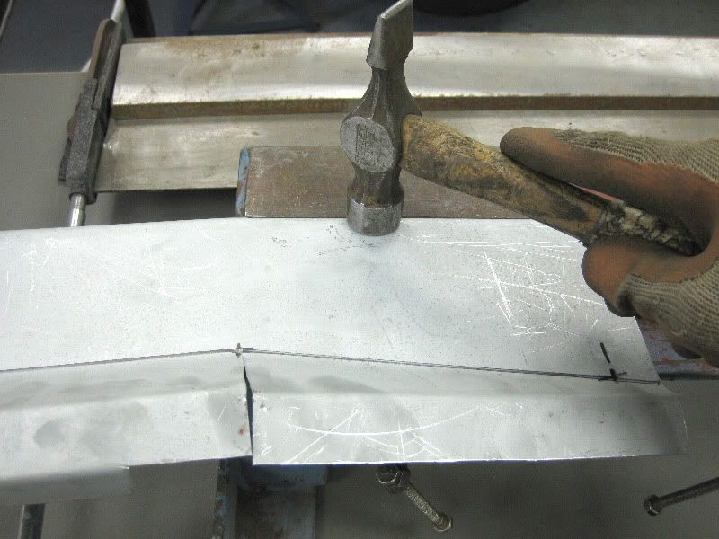 We get this, note the puckered edge, this is to be expected as there is too much metal, I could have cut it and welded it. 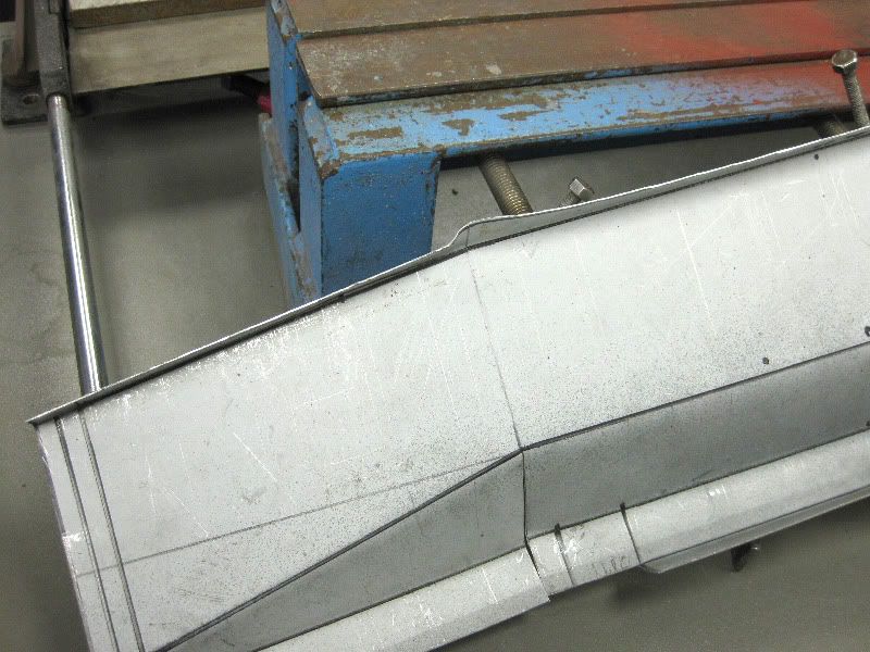 But instead just prefer to dress it over and force the metal into itself 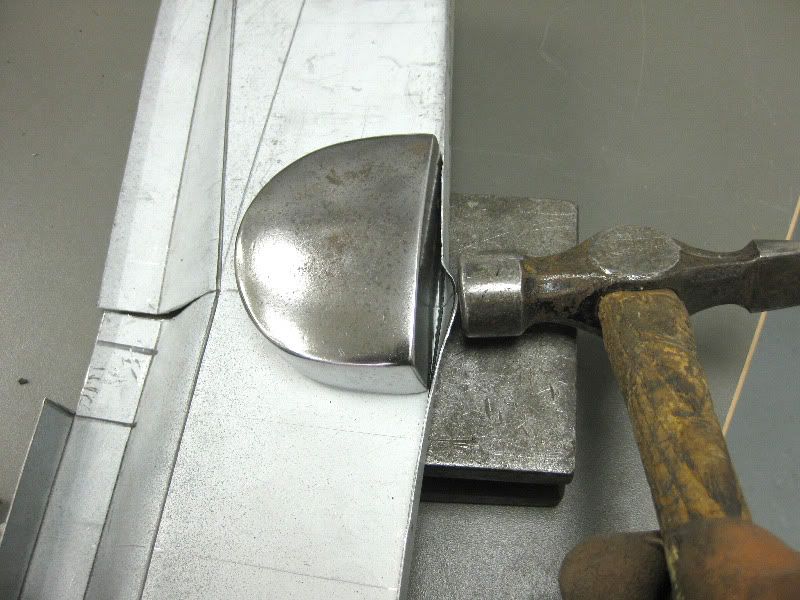 this takes several minutes or careful hammering as you don't want to stretch the metal. But you end up with this 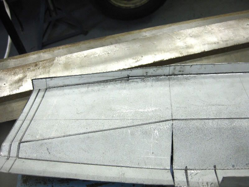 Then the ends need folding, due to the configuration of bends I cannot do these in either of the benders, so these have to be manually dressed up. Going back to my earlier point about thinking of the sequence, if I had done these first I would have really been stuck. So I use a steel block that I have 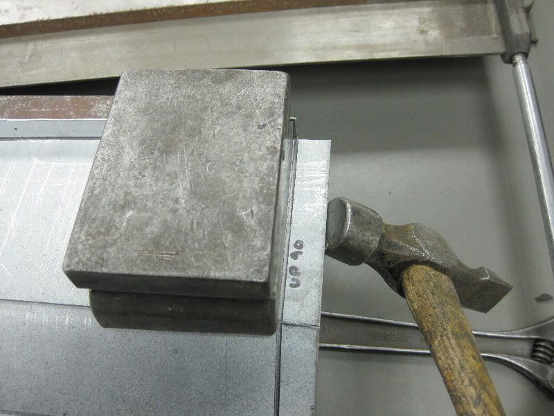 And dress the flange up against it 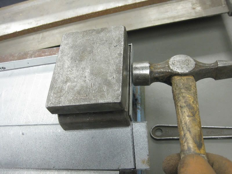 You get this  Then repeat 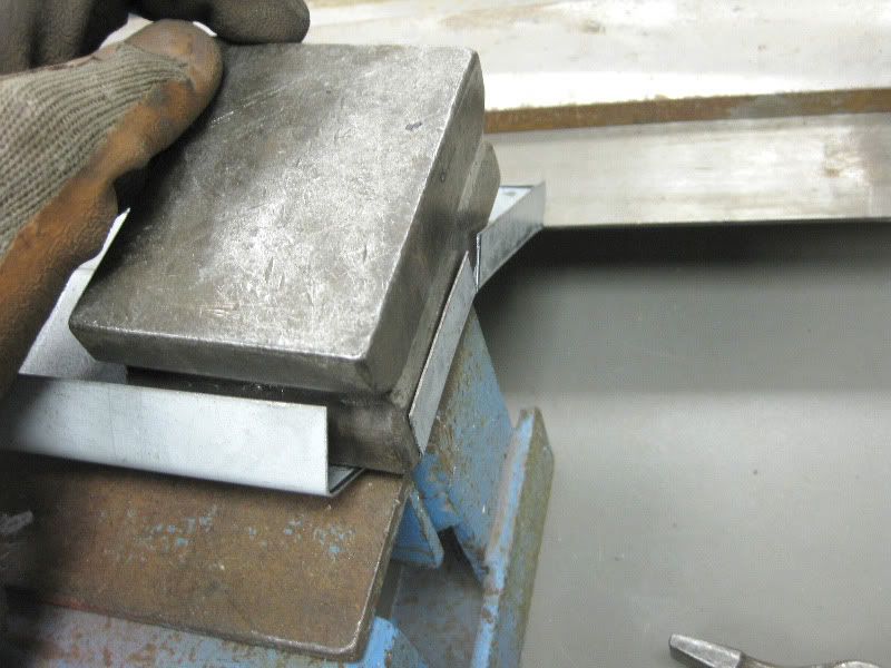 for this 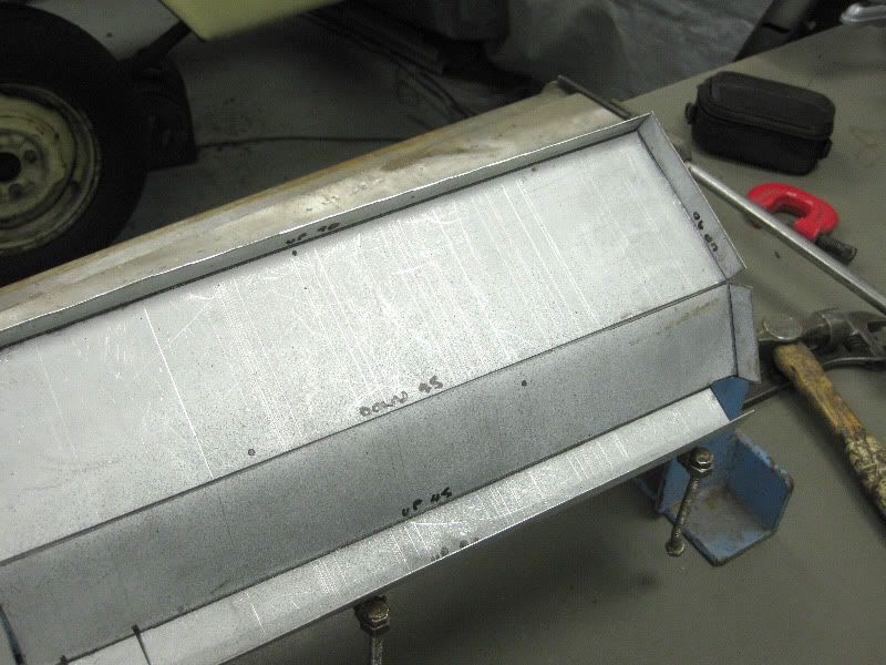 So that is the straight forward bits out of the way, I then need to detail the other end, a small snip is needed, here 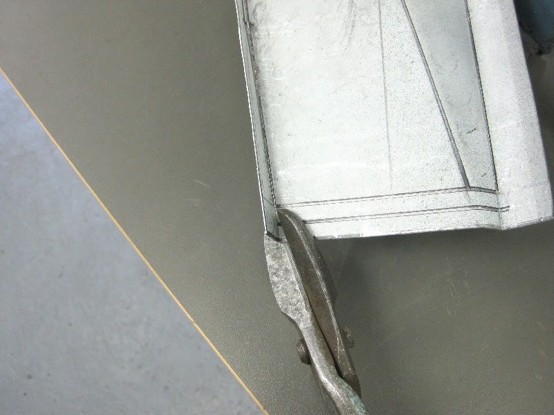 And here 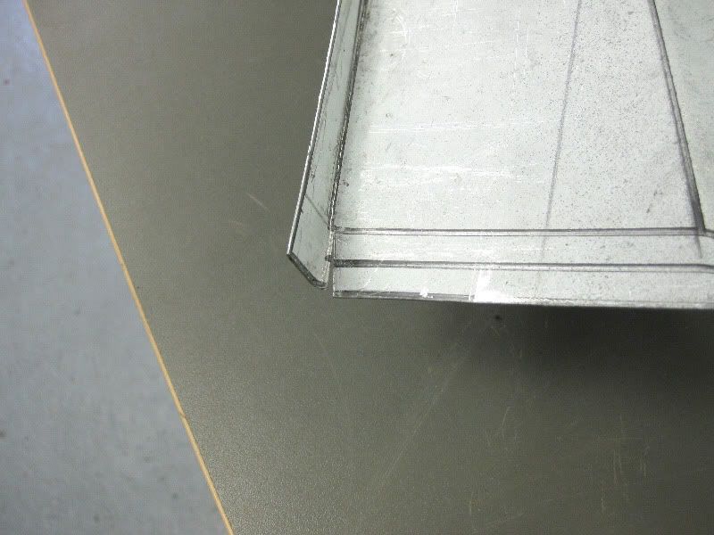 And then start to dress upto the block 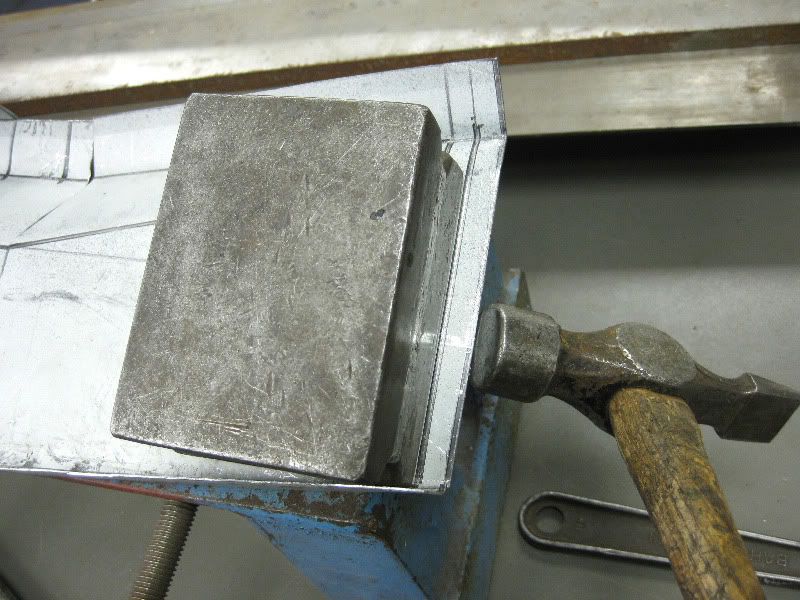 But only 45 degrees 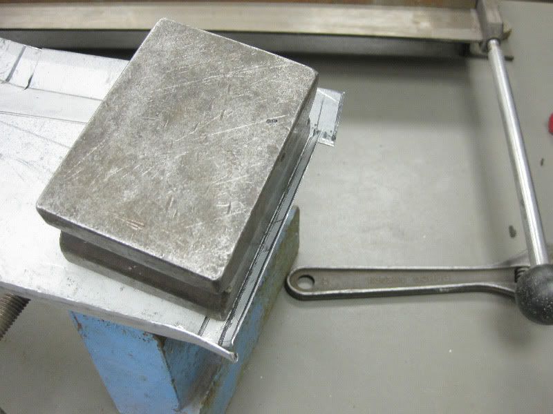 Then turn it over and dress it up again, smaller dolly needed this time, to get in, the bigger one is much better for dressing against as it is heavier. 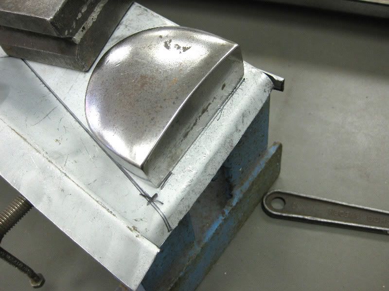 Almost there now 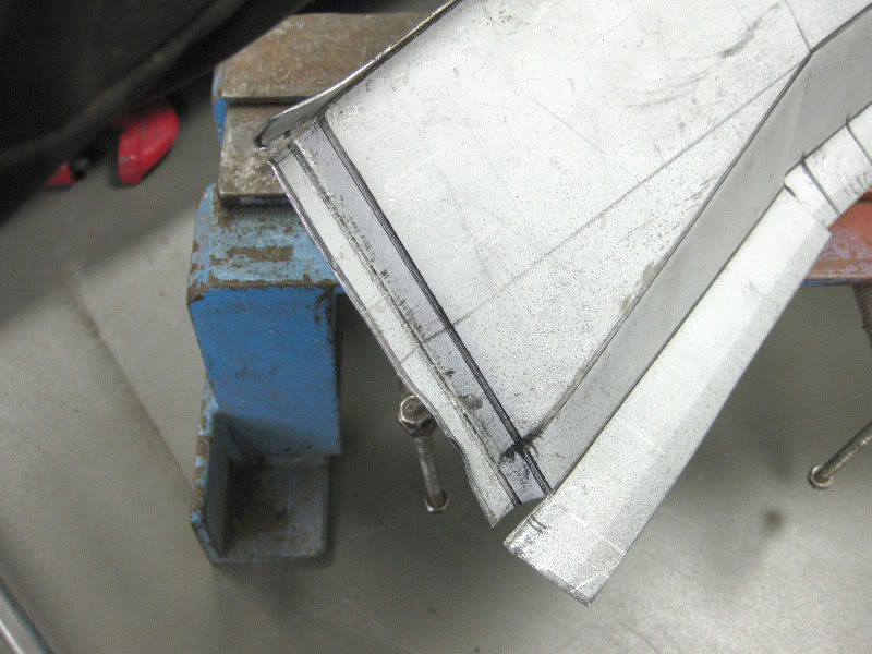 Just needs some tidying up 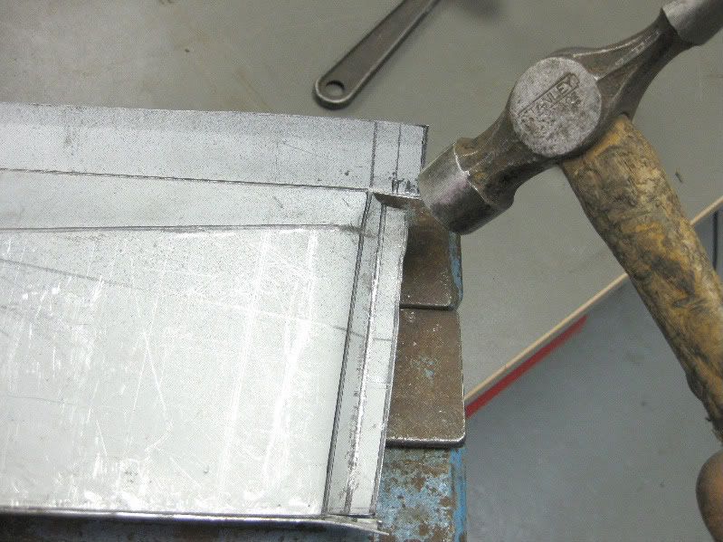 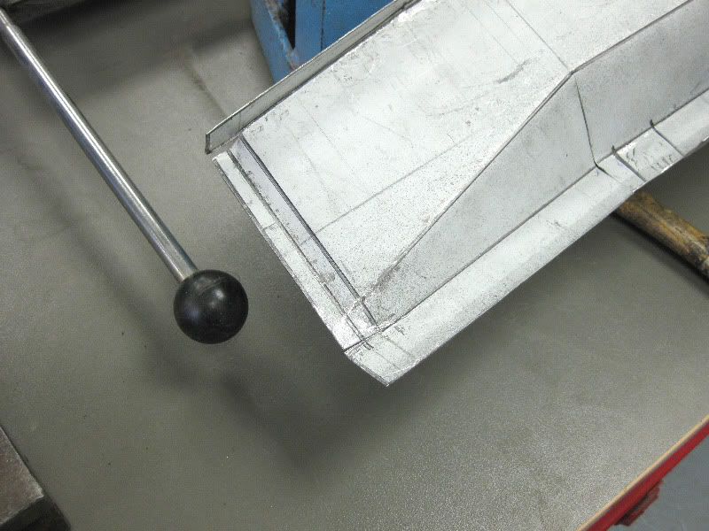 And there you have it, should be okay, and might need a little tweaking during fitting 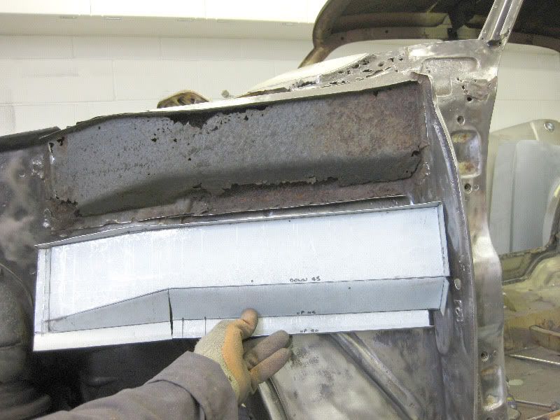 Once you break the panel down into individual bends, it is quite easy to create some fairly complex parts with just basic tools |
| |
|
|
|
|
|
|
|
I want to fabricate the top closing section while I still had something to measure 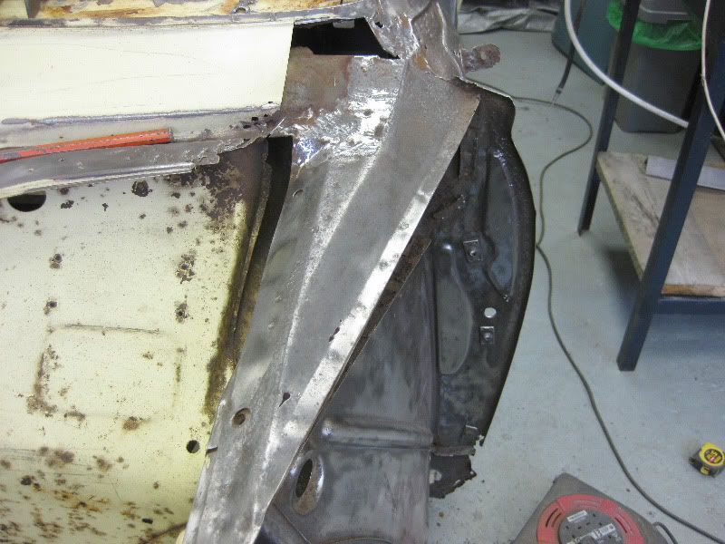 So out with the tape 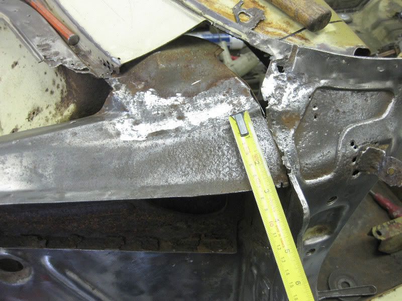 Transfer the dimensions 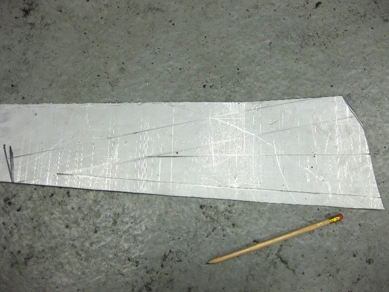 Cut 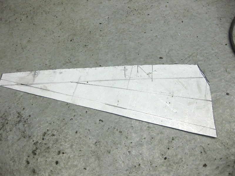 Fold  Fold 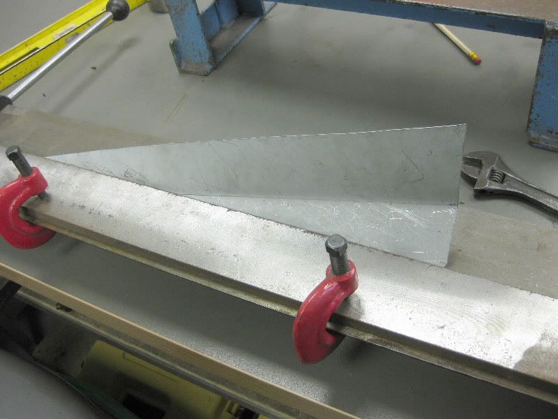 Getting there 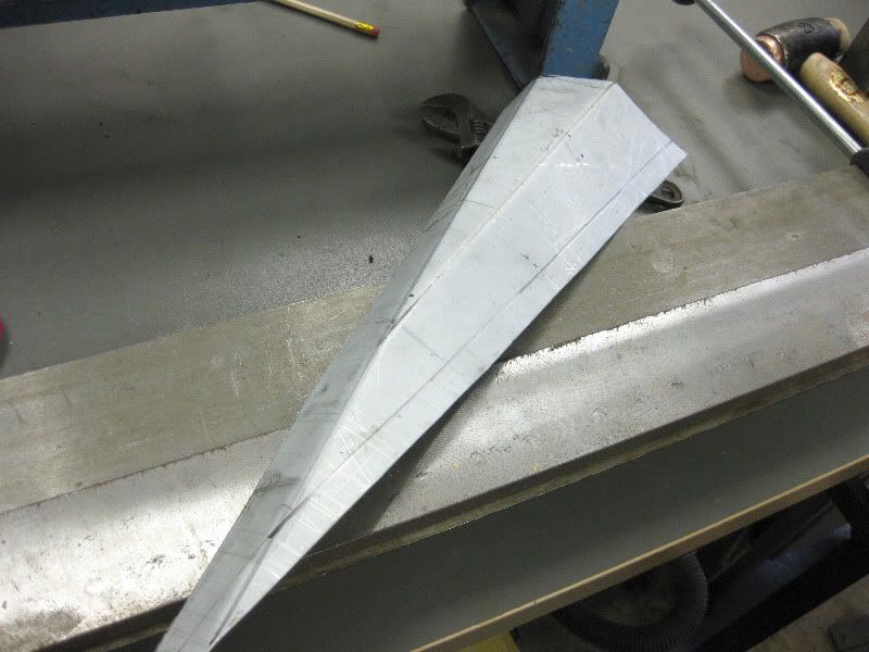 This bender is great for finishing off awkward bends 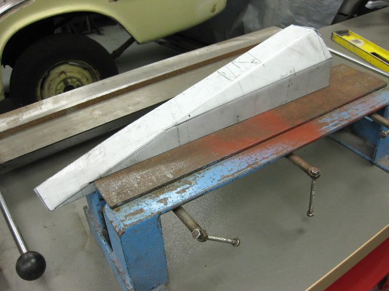 And over she goes 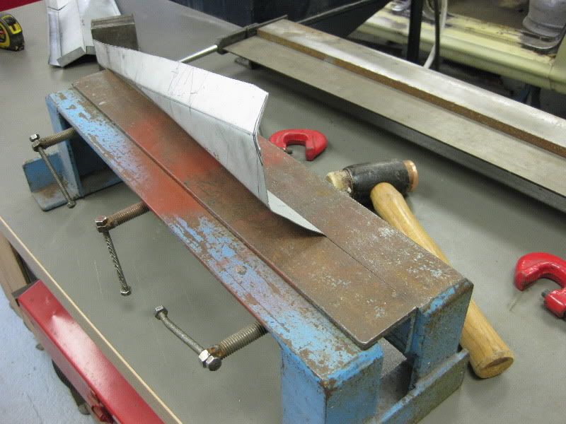 Almost done 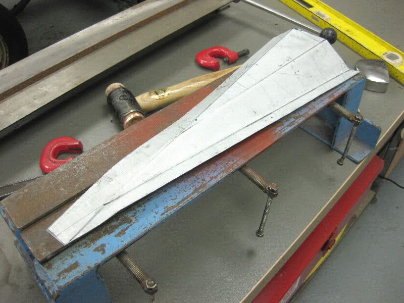 Needs a bit of tweaking here 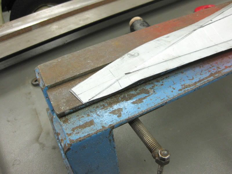 Mark and drill the holes 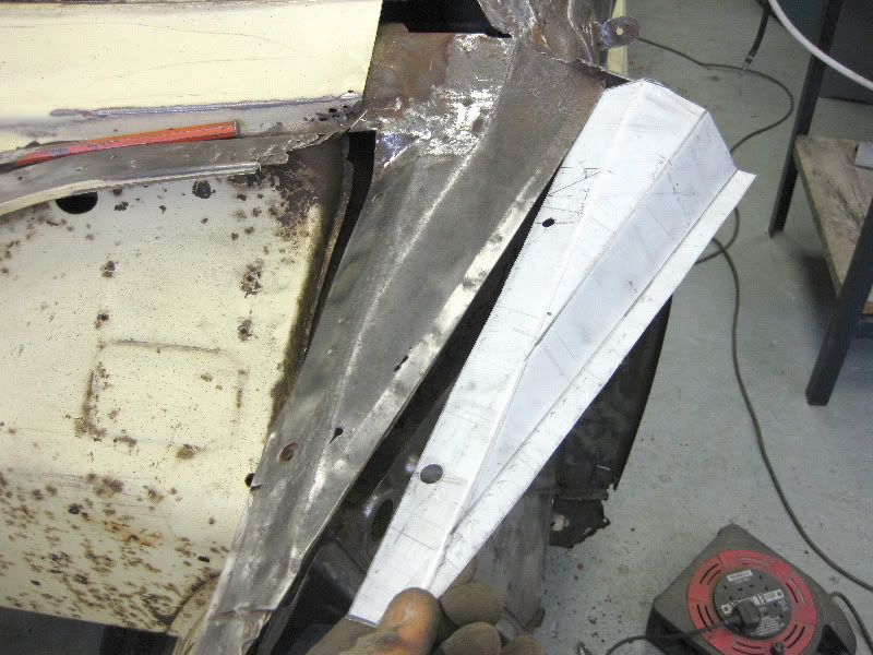 This then leaves this awkward little bit, needs a snip with the Snippers 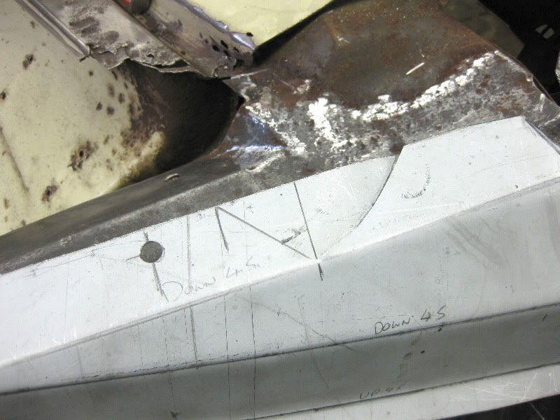 Then on with the mole grips 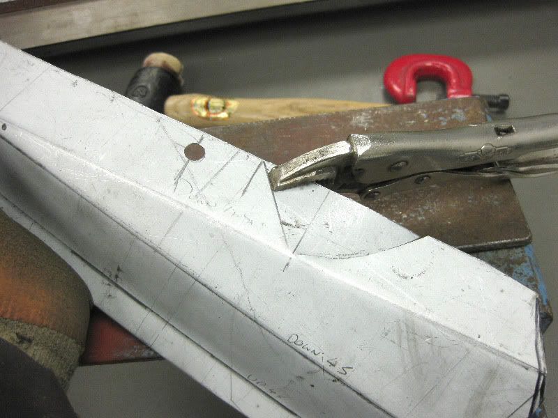 Up 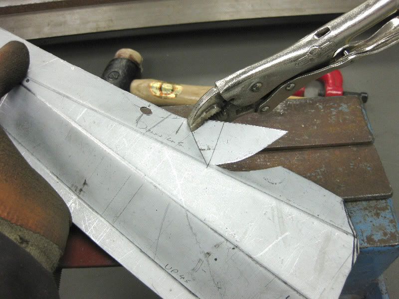 Down 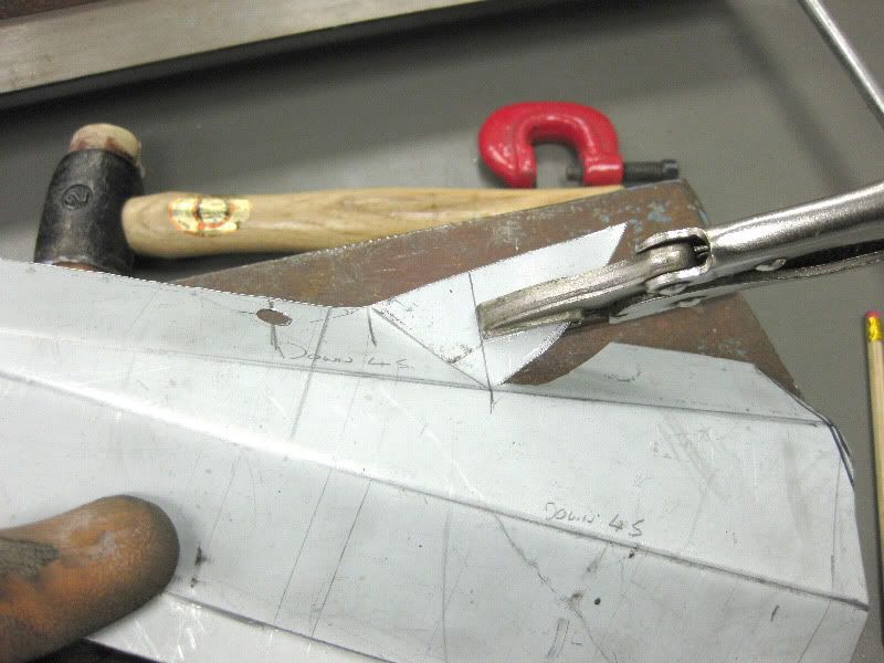 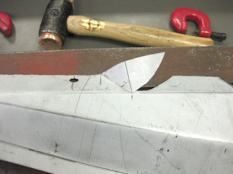 Hammer or should I say Dress, over the vice bed 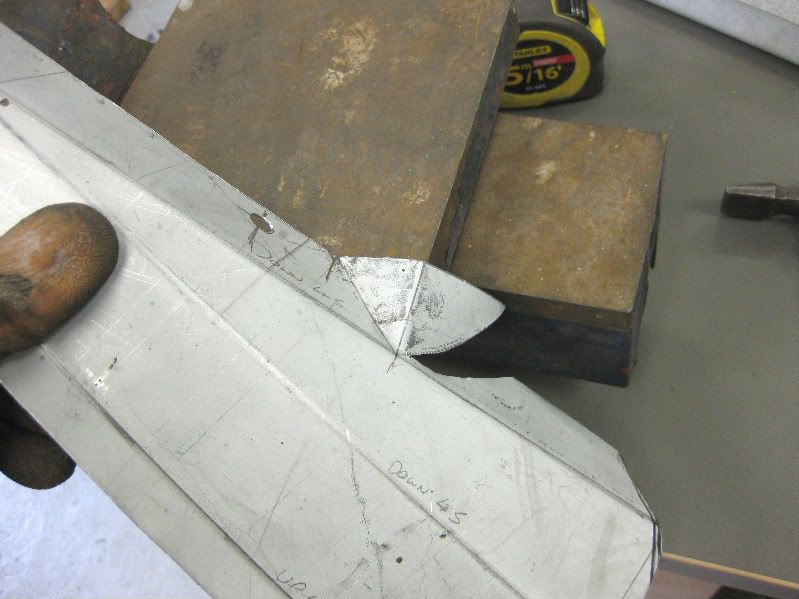 Ta Da 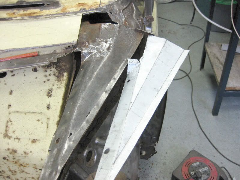 |
| |
|
|
|
|
|
|
|
As predicted once that part was cut off the part underneath was also rotten 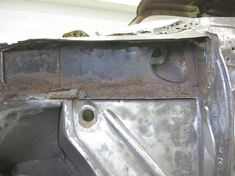 this is it marked up and cut out, cut the hole out using my Jigsaw 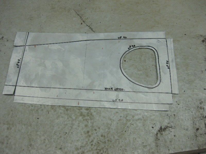 Then start the folds 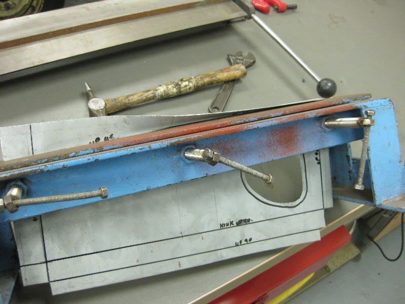 As you can see the folder has no bottom, so when folding tall sections you can just tip it on its side and feed parts through 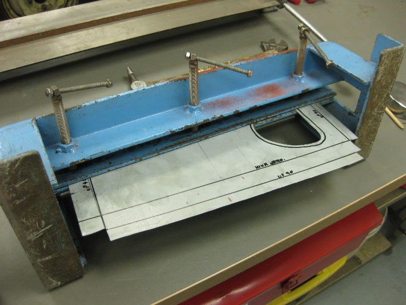 Then over and back in 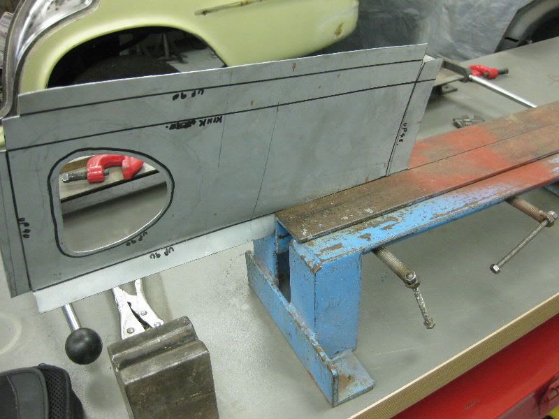 Leaving this 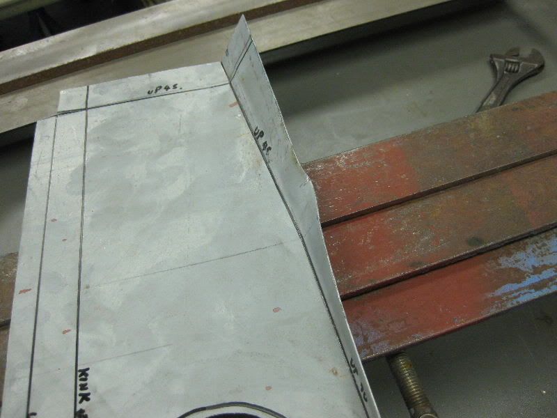 Dressed down to this 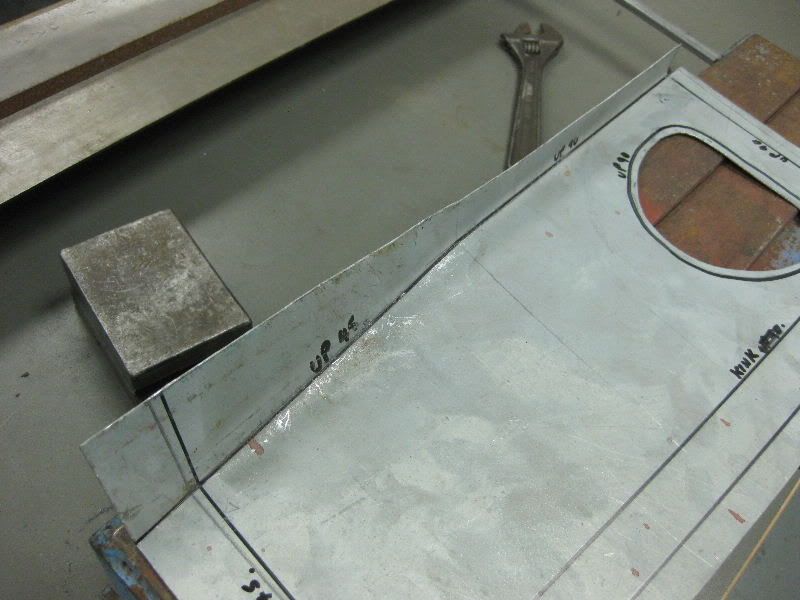 Then fold the other end 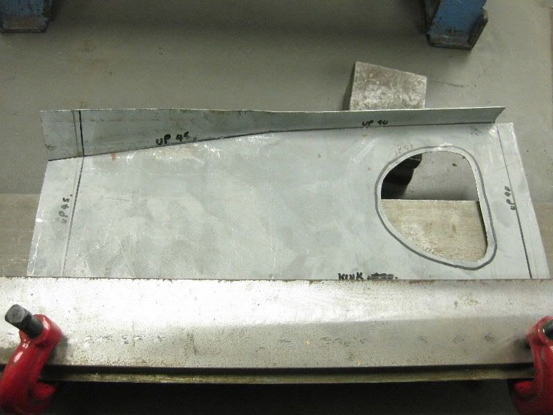 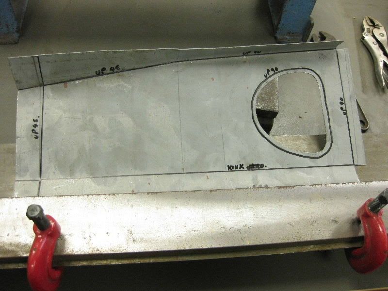 To this 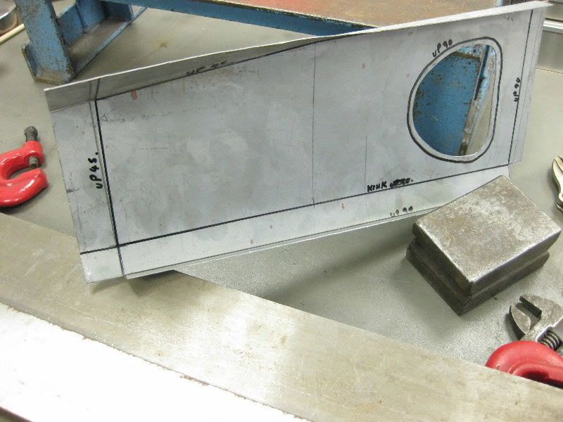 Ends up now 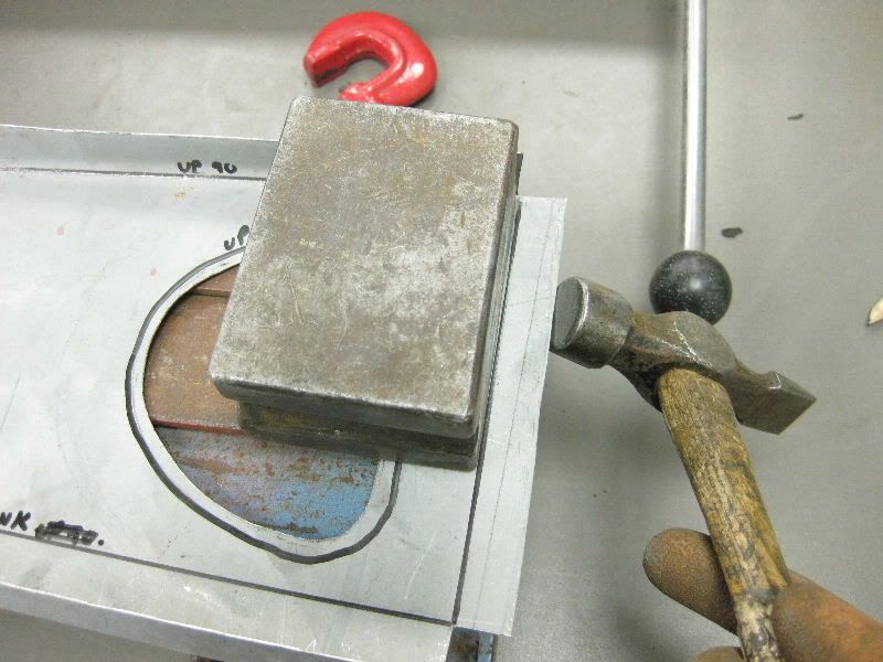 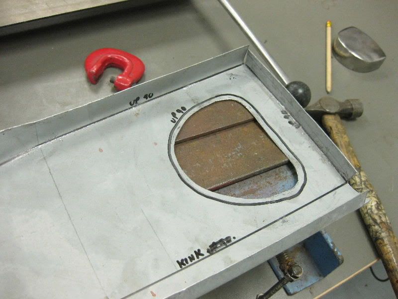 Other end 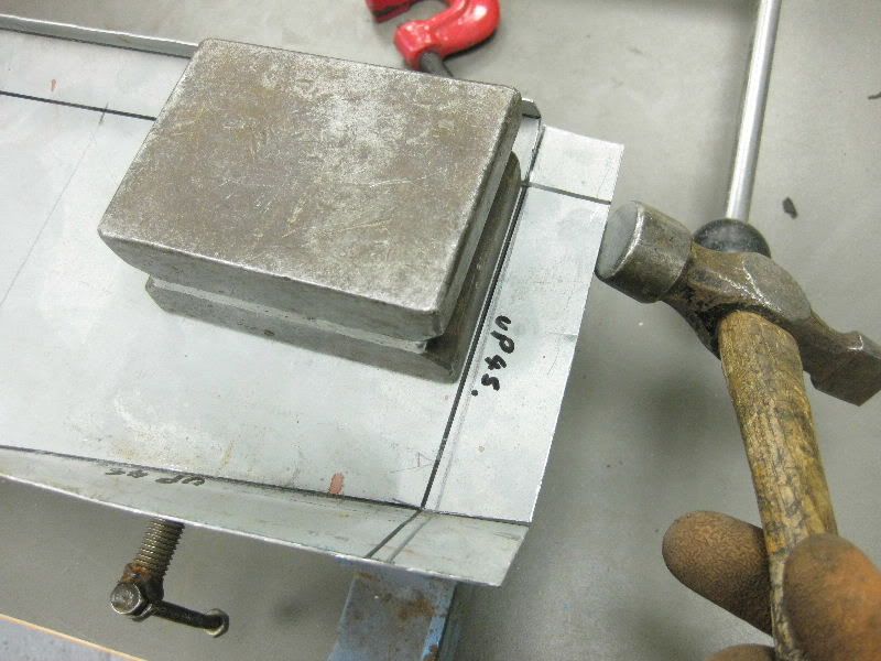 Thats the bulk of it 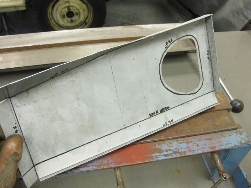 Just the edge around the hole, so start with the mole grips 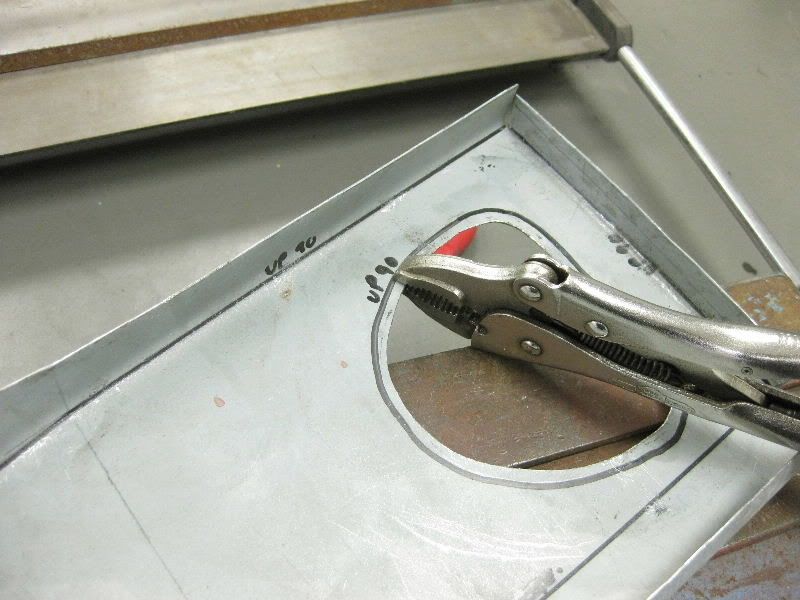 And up we go, a little at a time 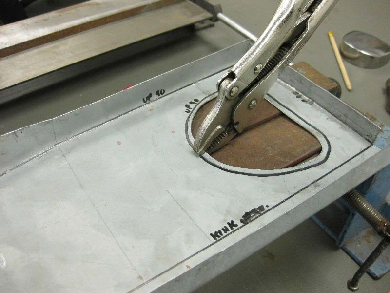 First time around 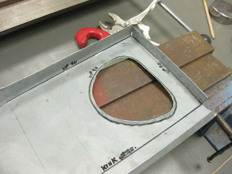 Second 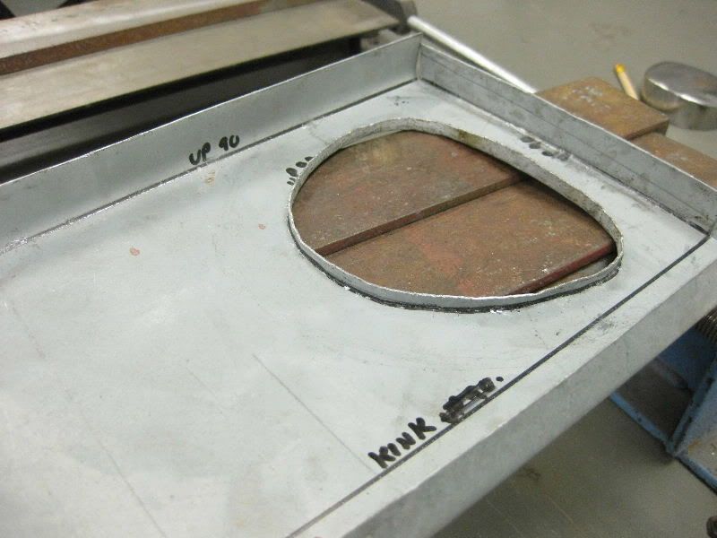 Just needs a little dressing to finish, on this type of bend you need to stretch the metal, so I use the cross pein end of the hammer against a block, as it squares things up, it also squashes the metal, thus stretching it too 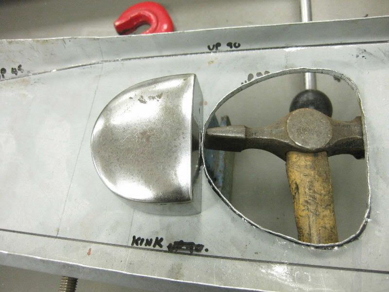 A bit more definition needed 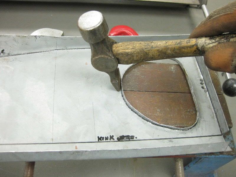 A different block for the tight spots 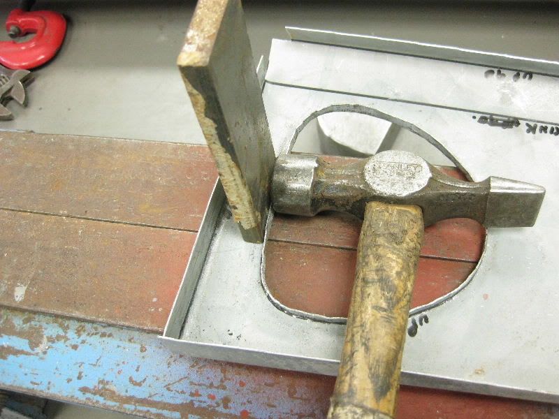 And there you are, just a run over with the file is all that is needed now 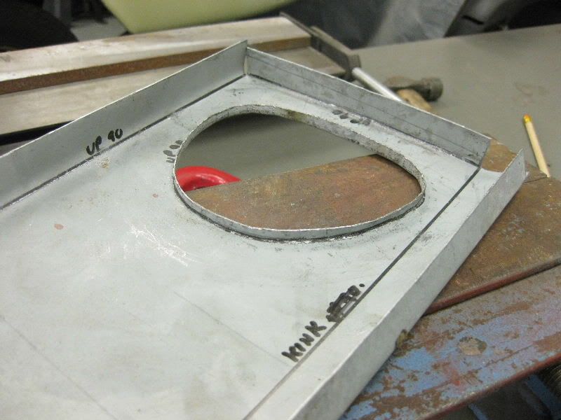 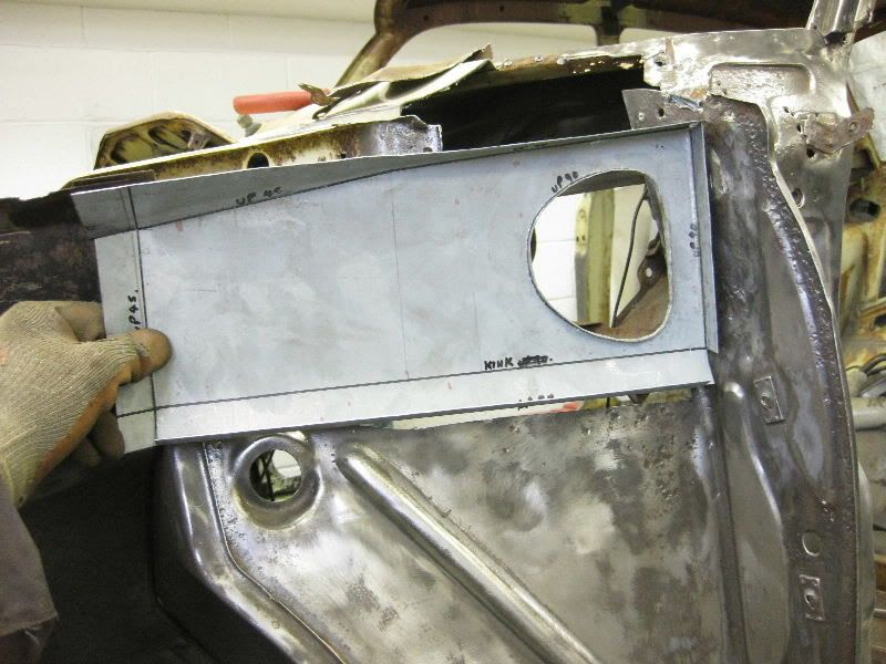 Oops almost forgot the bulge needed to clear the seam and let the water out 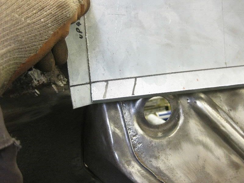 I am going to need this 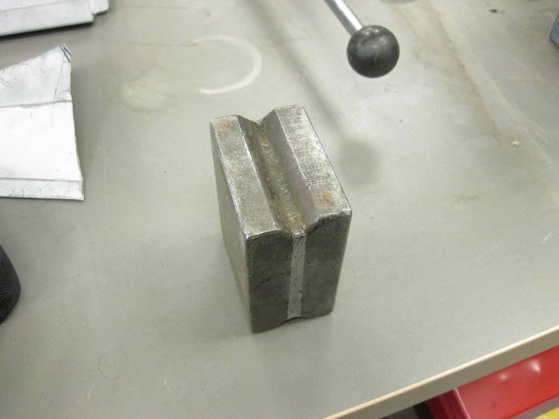 With this 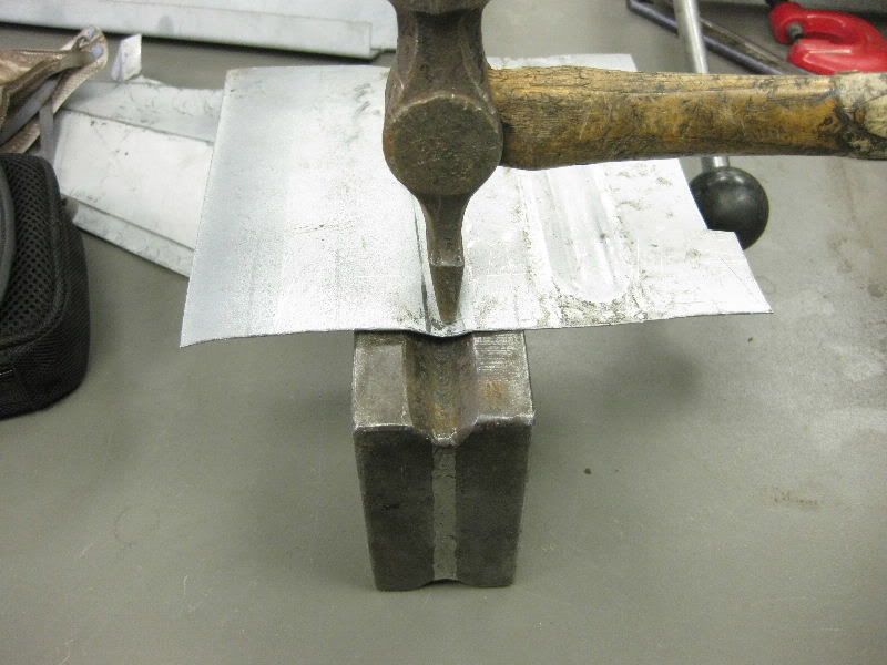 Bash Bash 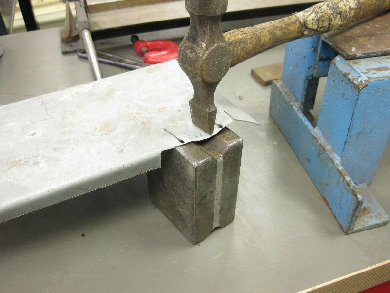 That gets us the rough shape 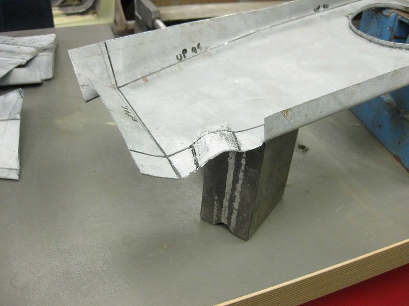 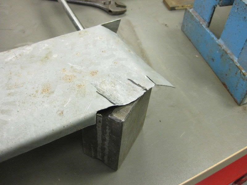 So then I need something round and hard, this will do 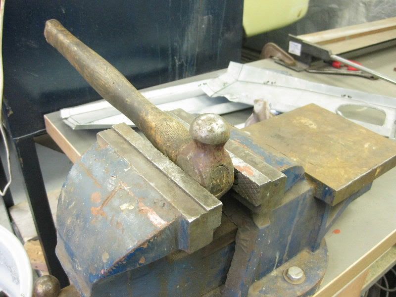 Then dress it as needed 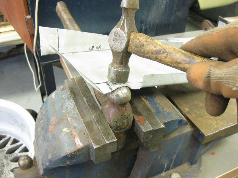  And check for fit 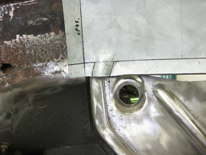 |
| |
|
|
|
|
|
|
|
So off came the next layer 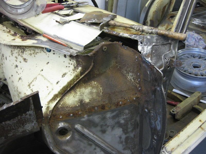 I think we all knew that was coming, so out with the twist knot brush just to check 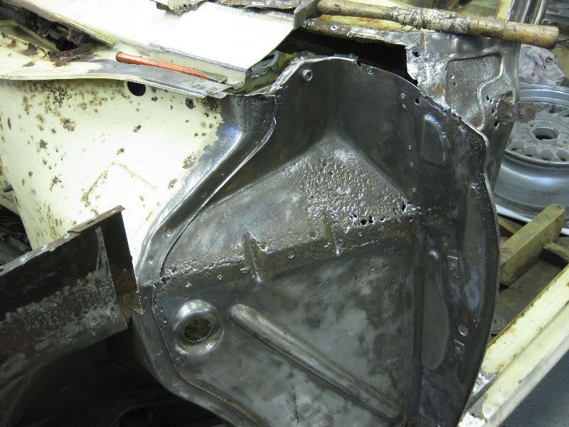 Yep well and truly needs attention it was actually worse than the other side and all needed to come out 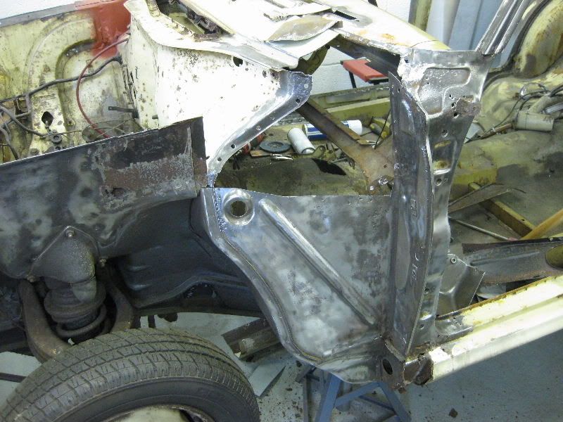 What you could not see was the back, which was inside the car, it was rotten right through. 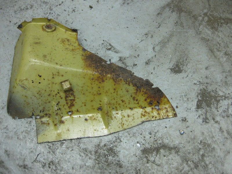 This looks like it might be tricky to make 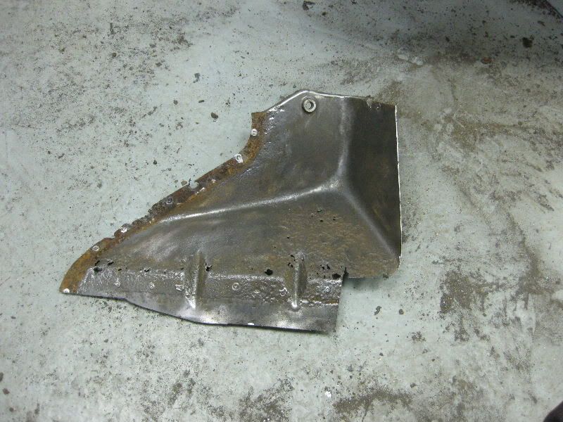 As it looked like I would not simply be able to measure and mark out this part I made a cardboard template and taped it together, this is the flat pattern. 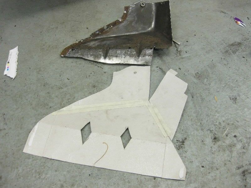 Transfered to the steel 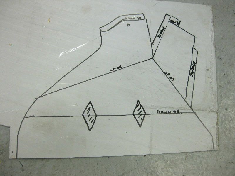 Cut out 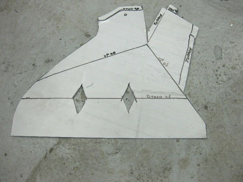 and start to fold, again thinking of my bend sequence 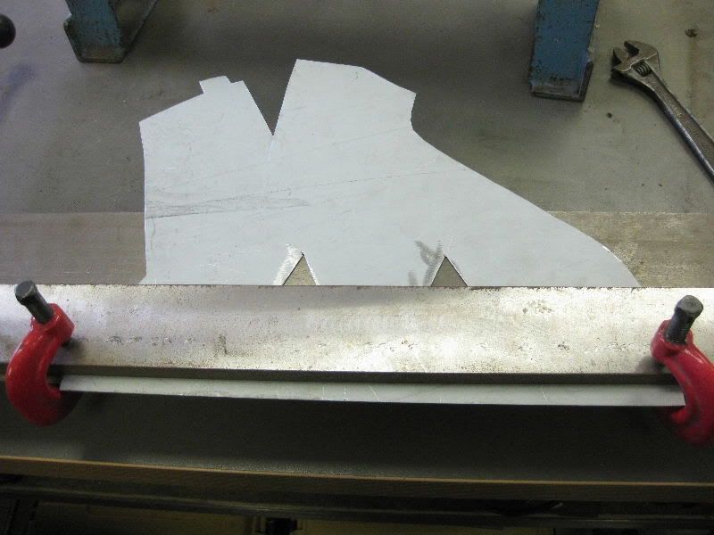 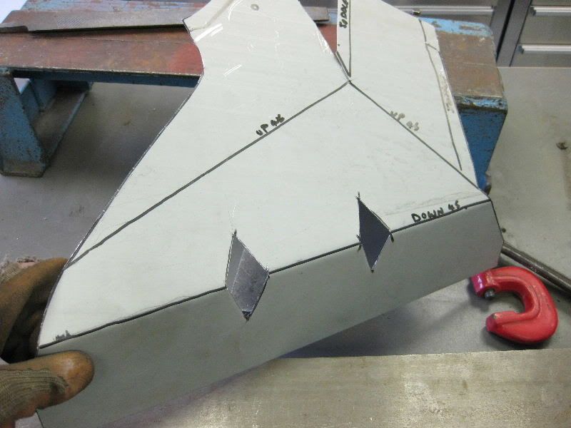 The next bends are radiused so I used a bit of round tube to help in my bender 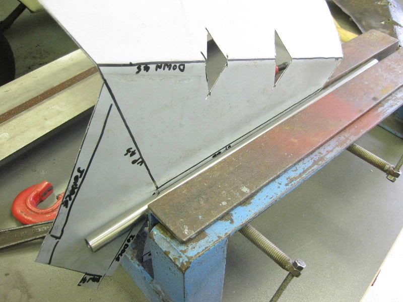 Up she goes 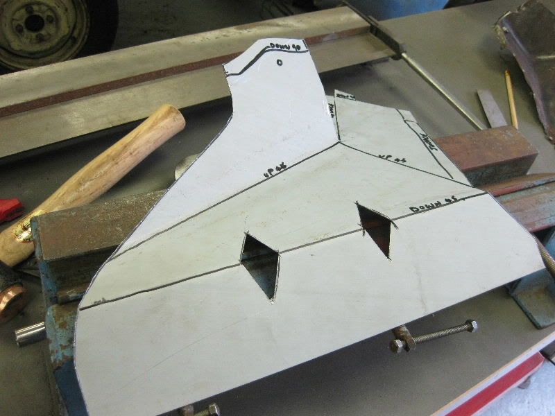 Where possible for strength and ease I prefer to join panels with the Joddler, so this joint will be joddled, this needs to be done before that section is bent up 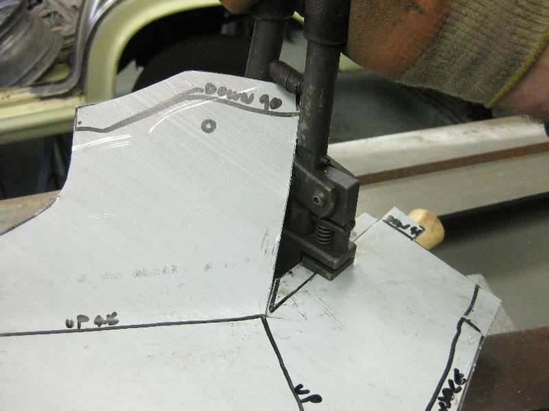 But I also need to part radius this joint as the fold up this seam is also radiused 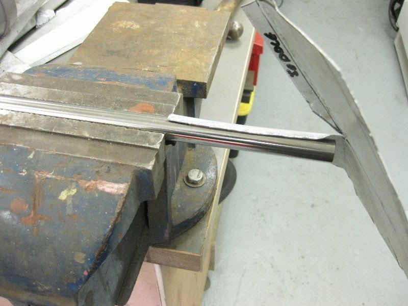 Both sections need doing 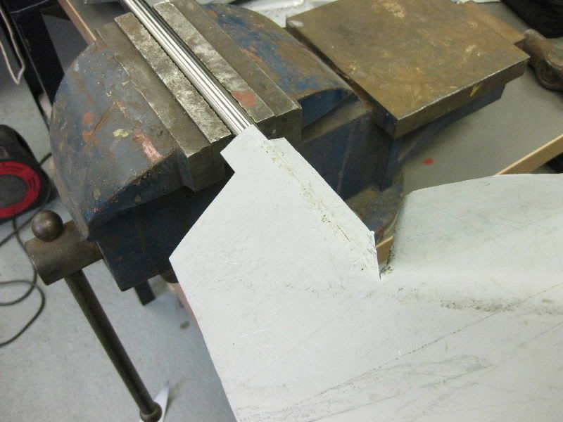 To this 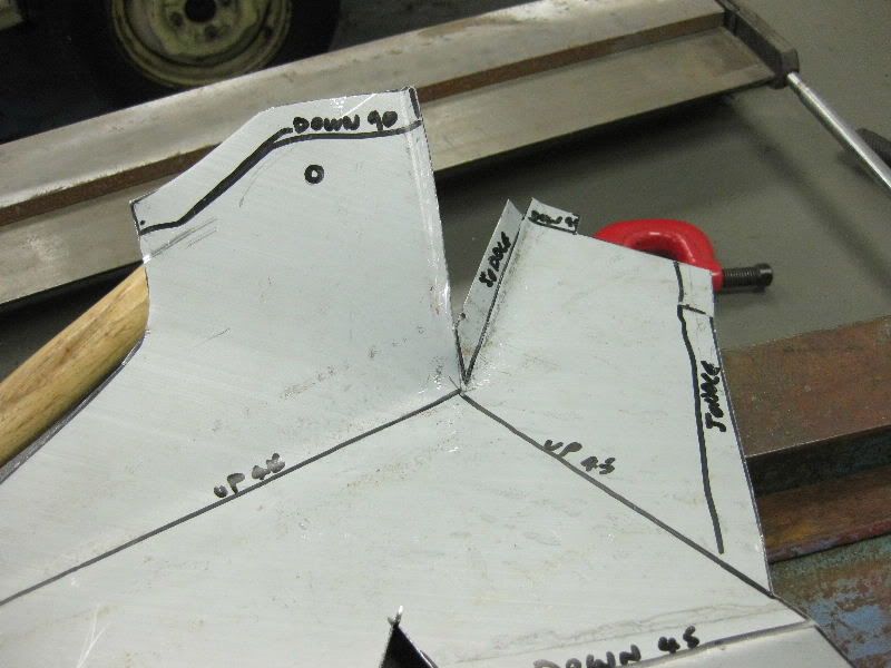 Couldn't get it back in the bender so clamped the tube to it and folded it up by hand 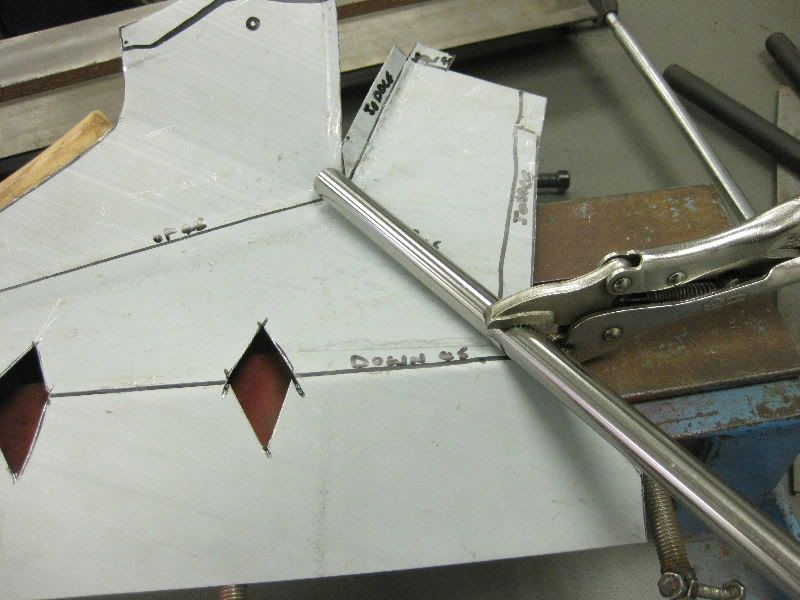 To this 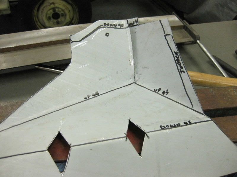 Then need to fully radius the joint where the 3 radii come together, so out some the 2lb hammer again 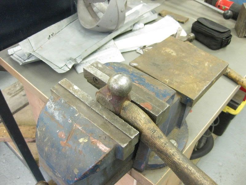 Bash Bash 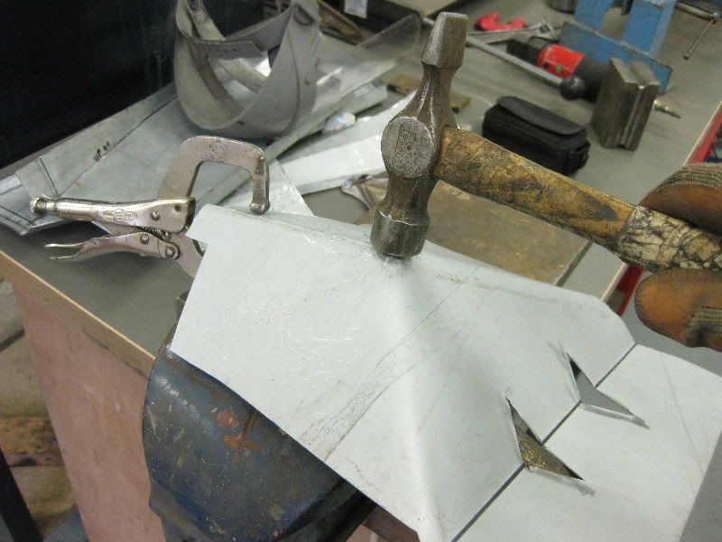 Can you see what it is yet ?? 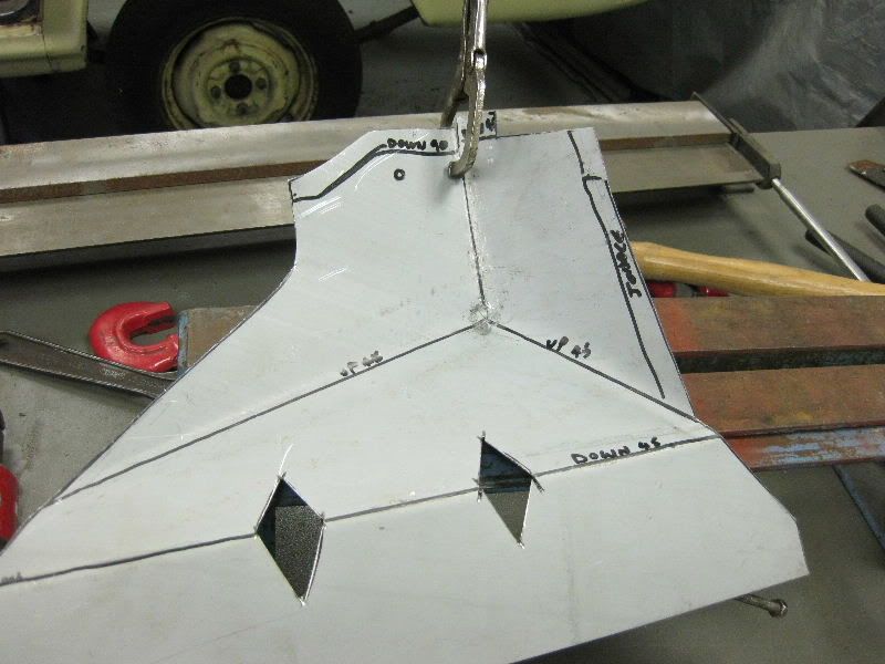 As mig weld is very hard and not easy to hammer, I spot welded the joint first to then allow me to dress it into the right shape 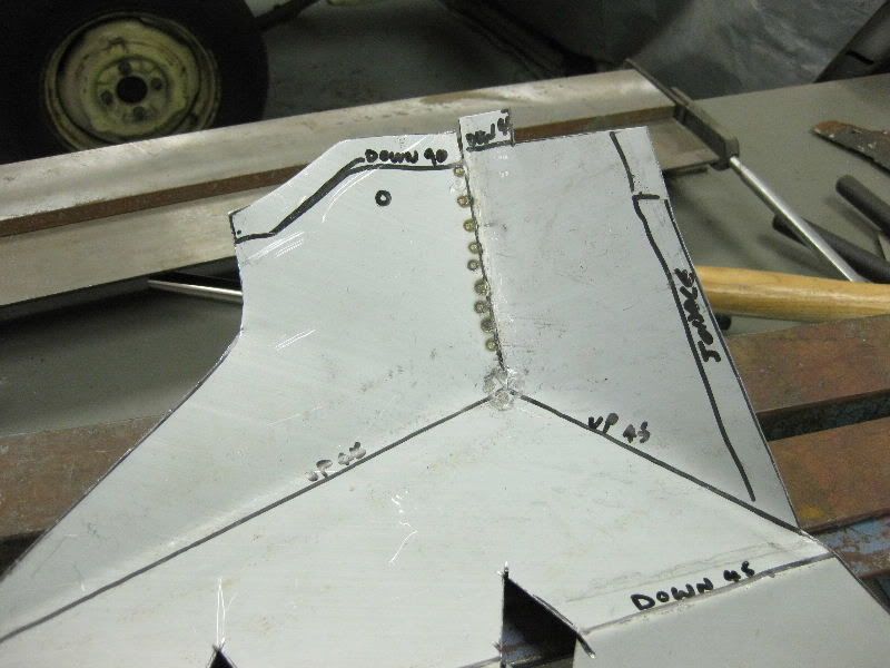 Bash Bash 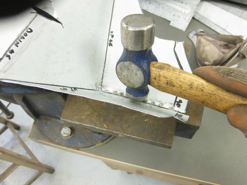 Now nicely formed 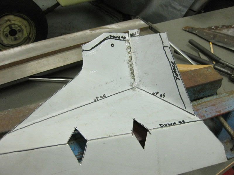 The top flange next 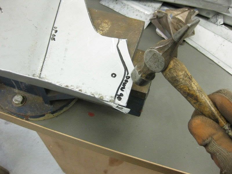 Stretch with this end 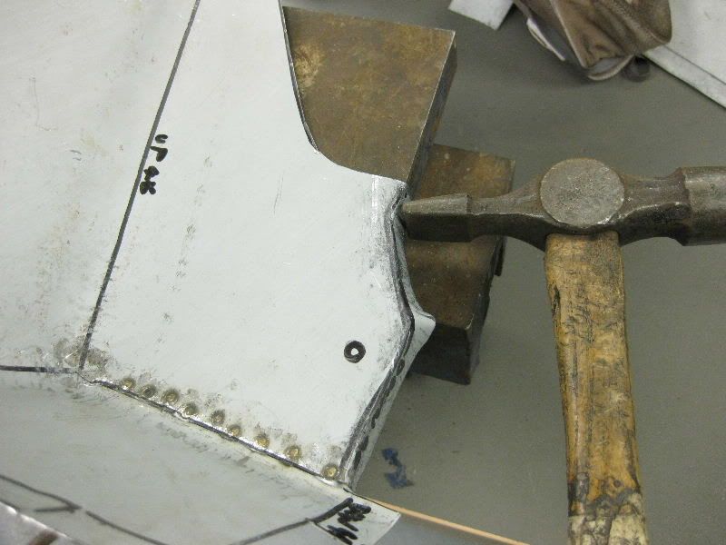 Puckering needs shrinking 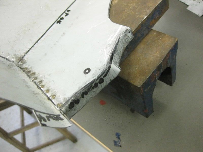 Use Raw Hide mallet to shrink, the raw hide allows the metal to be dressed into itself without stretching it and helps shrink any excess, it is a slow process and needs plenty of practice 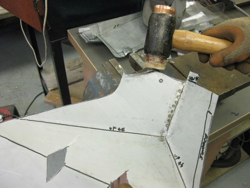 Looking promising 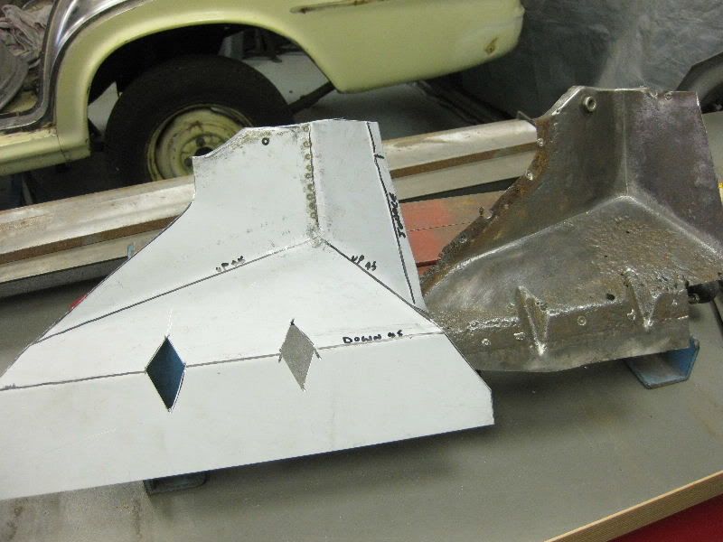 2 offcuts for the flutes 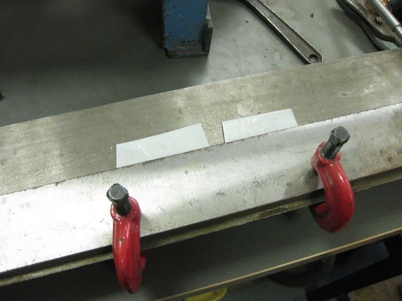 Bent up 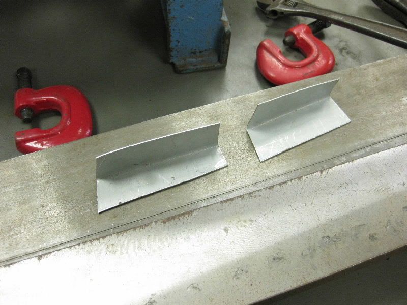 Layed on and Marked 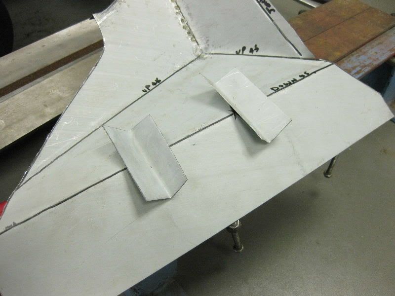 Cut out 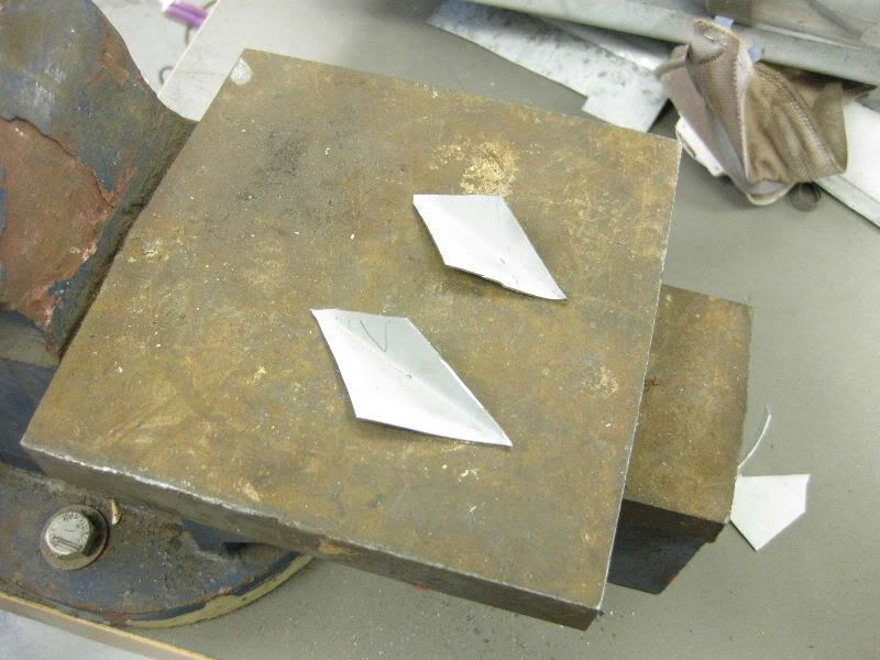 Offered up 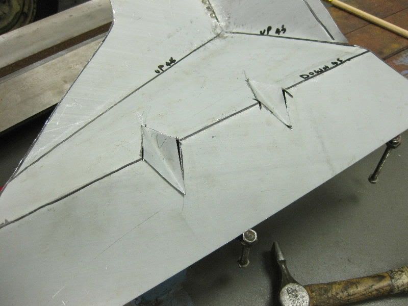 Trimmed and Tacked 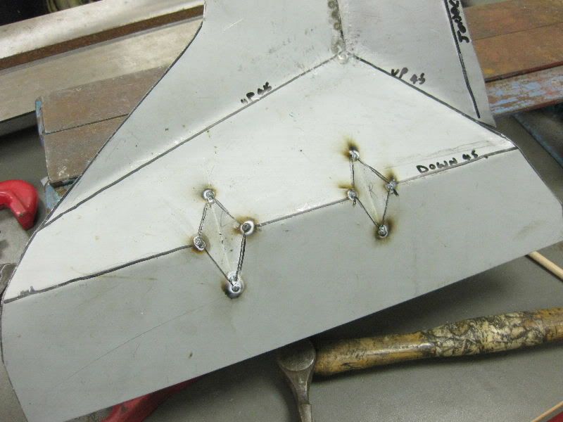 Welded 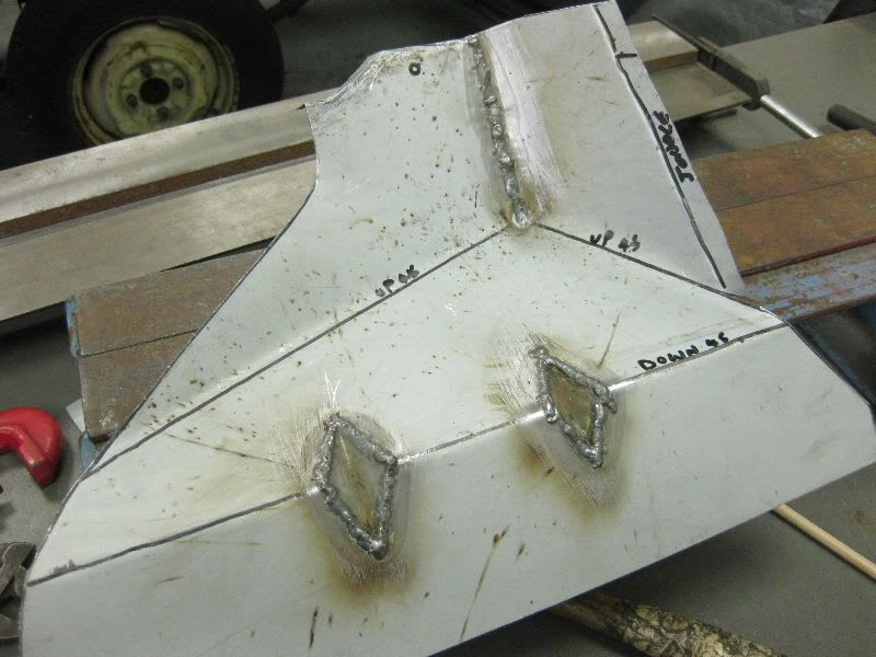 Cleaned off with the 40 grit flap disc on the grinder 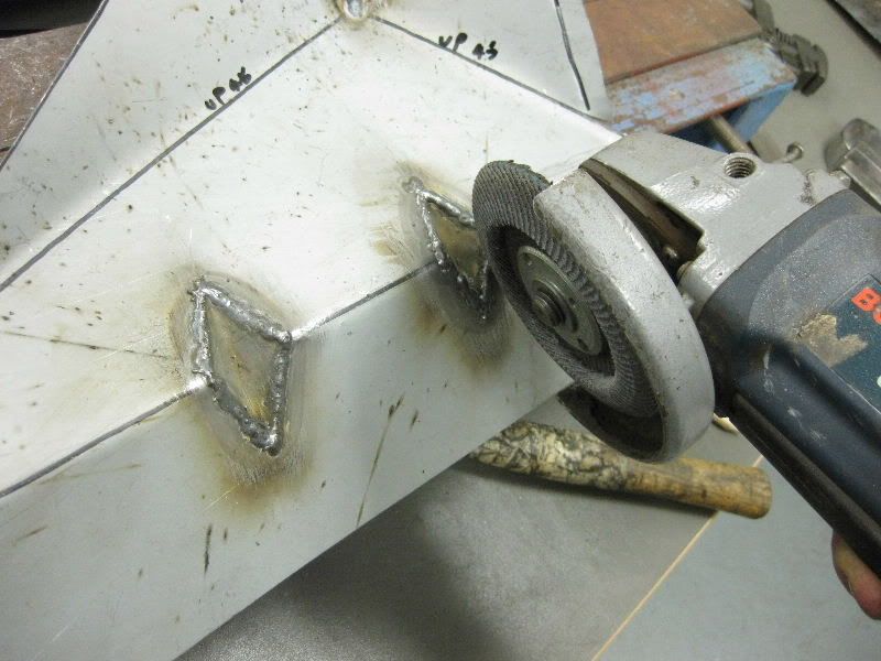 and a 40 grit flap wheel in the die grinder 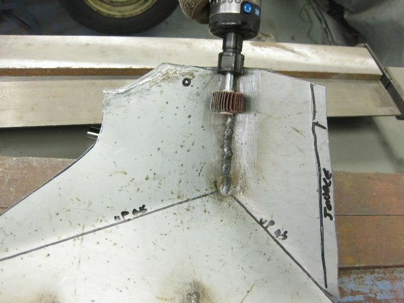 You get this 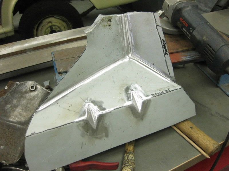 Then over the whole lot with a 40 grit DA disc to remove the flap disc marks and the weld splatter, should really have used anti spatter spray but I did not have any 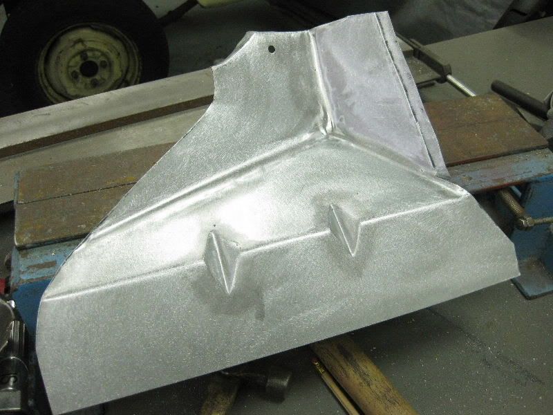 Welded in the bush for the bonnet hinge and tacked it into place 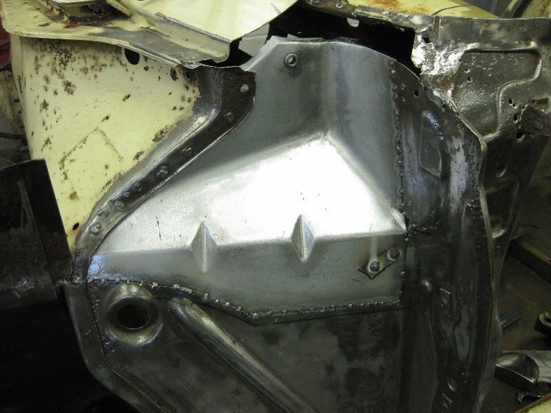 This section also needed some attention 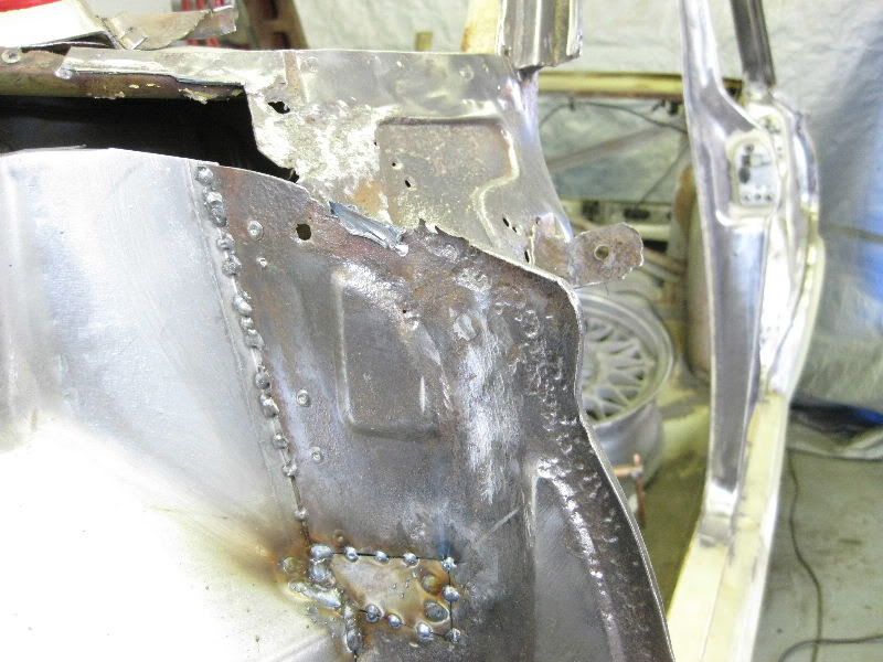 So marked it out, leaving some metal for the flange, and cut it out 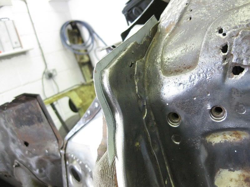 Then dressed the first flange over in the vice 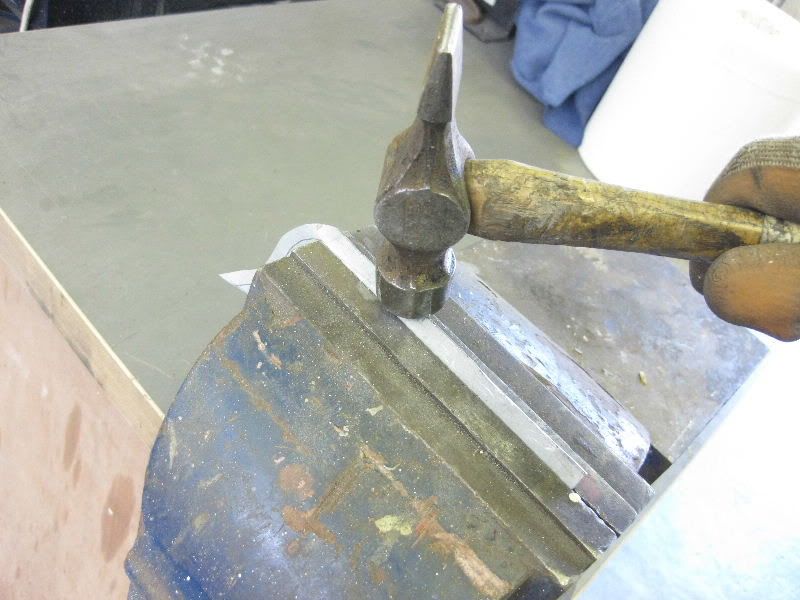 Which gave this 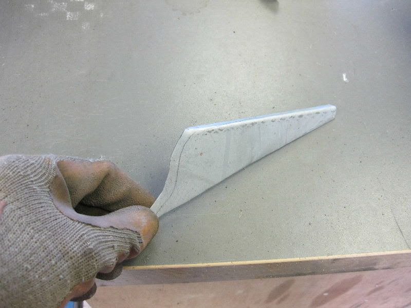 The fiddly bit needs the mole grips 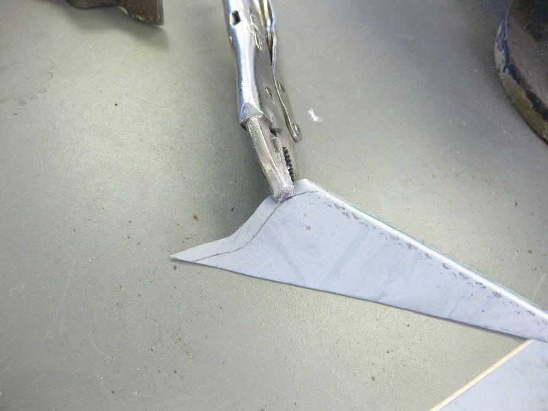 Which leaves this, roughly right but needs more detail 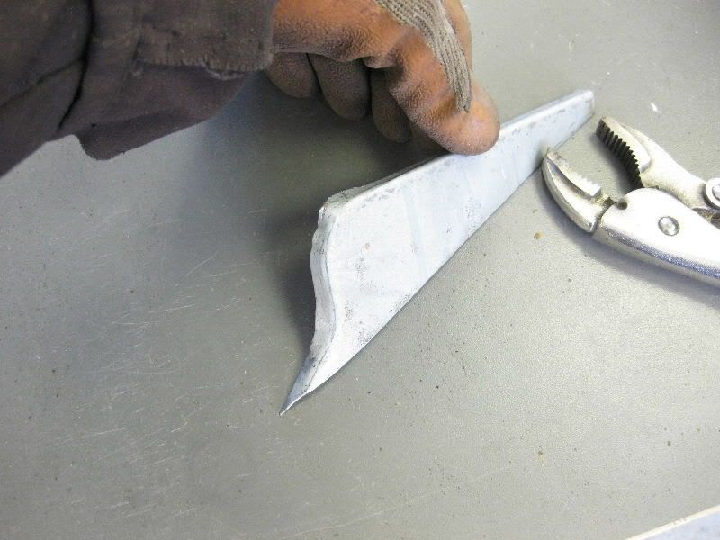 Need a small radius work piece, this will do 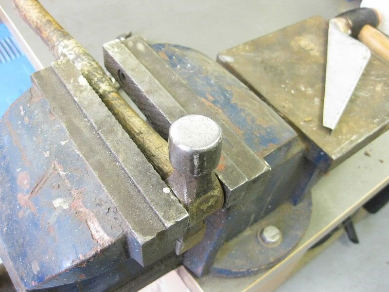 Then as before shrink and stretch where needed 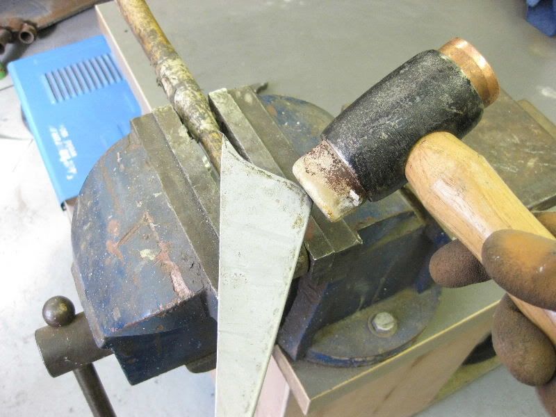 And tack in, copper block used again to stop the edge burning away when welding, the trick is to start welding on the copper block and work inwards, rather than outwards. This would be my top tip for any edge welding like this whether using a copper block or not, start at the edge and weld in, if you work out towards the edge, the heat builds up and the edges can easily be burnt away. 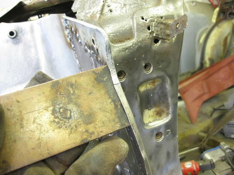 When you pull the copper away you are left with this, weld is sticking past, no burning away, and then just grind the excess down 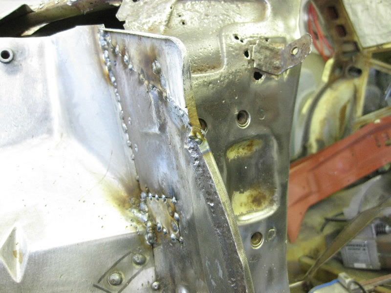 So all bits now tacked in 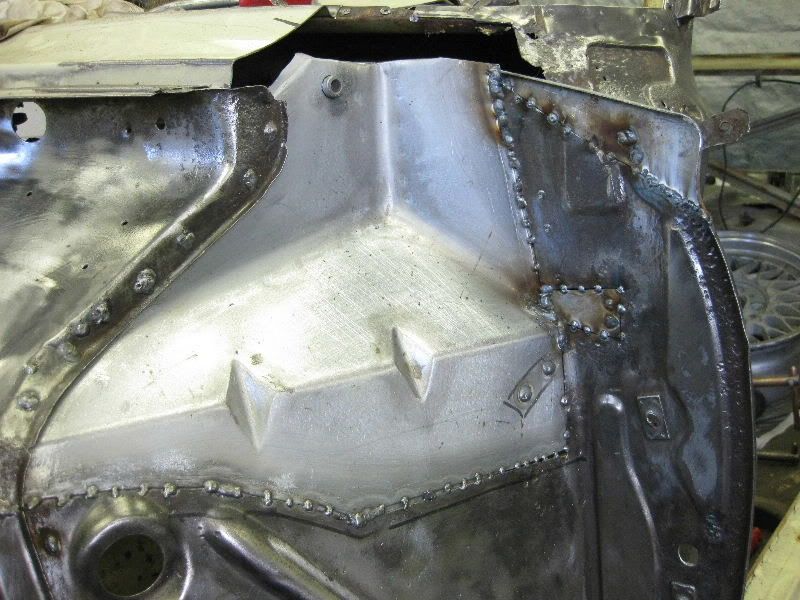 Welded and dressed off 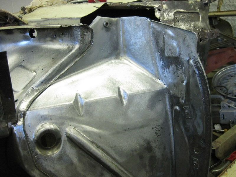 |
| |
|
|
|
|
|
|
|
You will have to visualise a scenario of your own for this, perhaps the bottom of the A post I repaired earlier, or a wheel arch section, anyway this is what we are trying to achieve 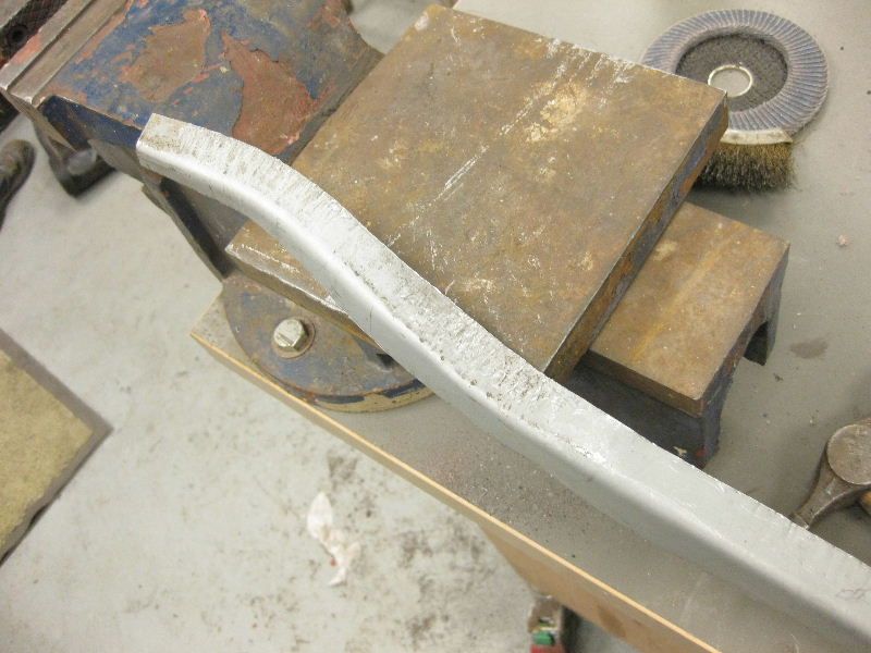 This uses 2 of the basic metal shaping techniques, shrinking and stretching, we have touched on them briefly before, you could just of course go out and buy a Shrinker and Stretcher, and to be fair I have one and use it a lot, but that would not be as entertaining. So start with a scrap of metal, footprint is optional 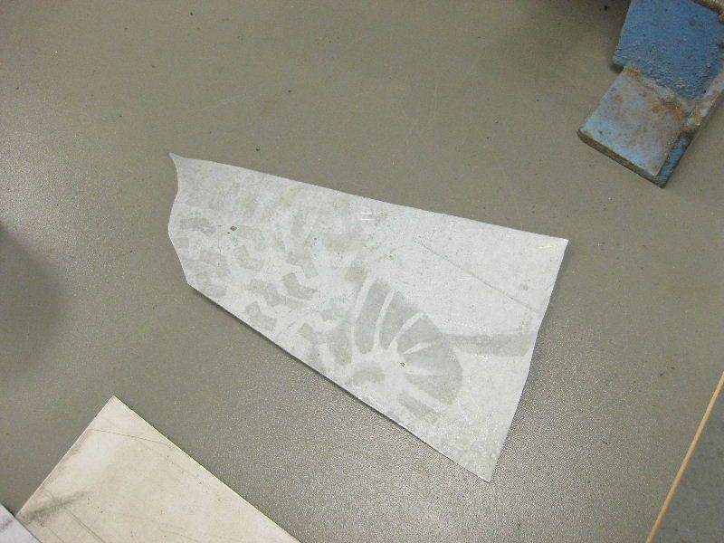 into the folder 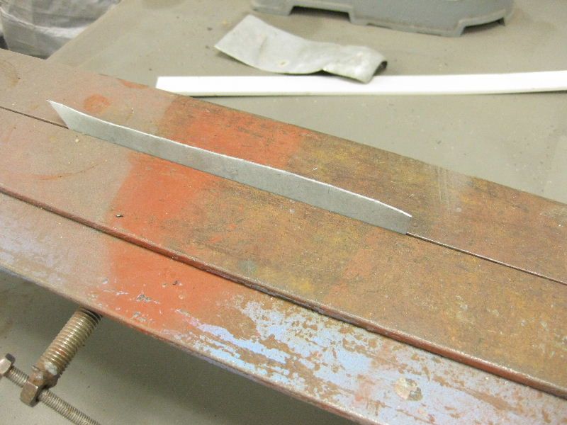 and dress it over 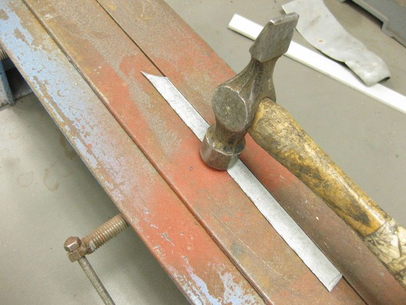 to get this 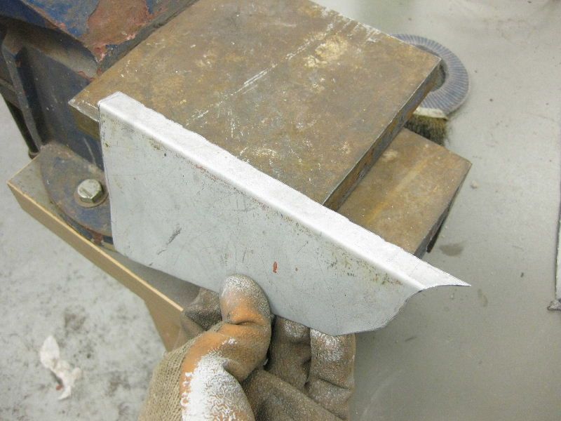 We are going to curve the small flange, the smaller it is the easier it is, it would be pretty impossible however to curve the other flange which is about 3" wide, so if you had to curve that much, I would probably weld a bit on after. Anyway, back to the task in hand You need your cross pein hammer again 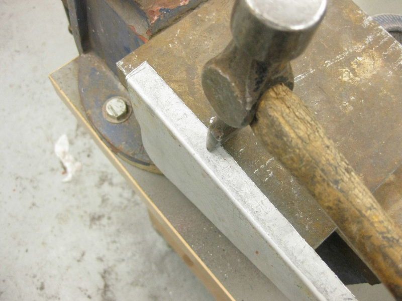 and then strike the edge of the flange, against a hard metal surface 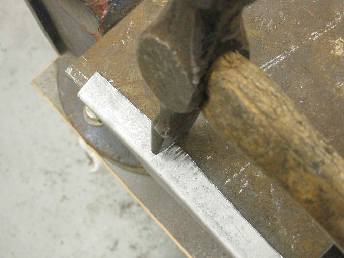 This does mark the metal, but that is okay, what it is doing is stretching it, and as you stretch the outside It starts to curve, this was after about 30 blows 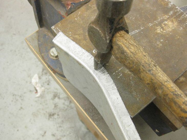 and then just keep at it until you get the curve you want. moving up and down the flange as needed 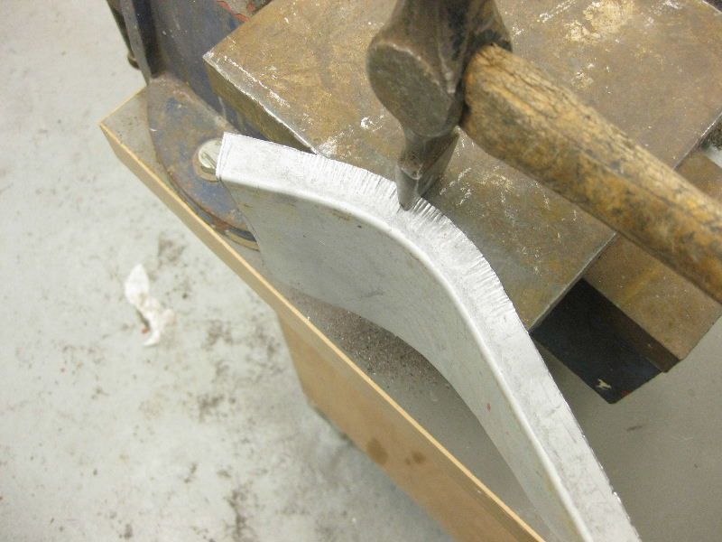 Obviously, all this bashing distorts the edge a bit 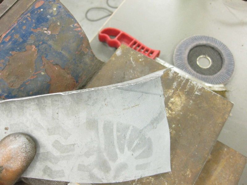 But you can dress this flat with the flat end of your hammer 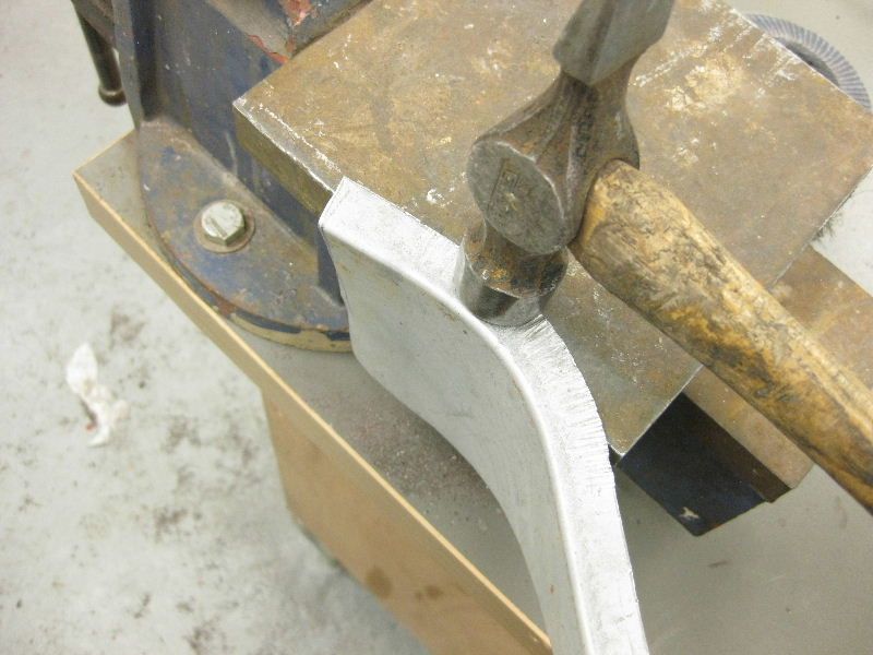 Turning it over and dressing from the inside if needed 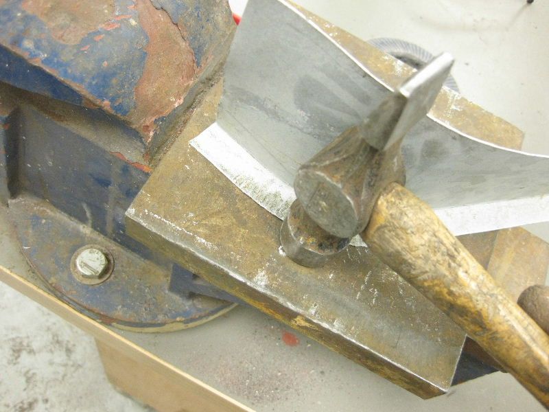 and there we have it, the beginnings of a curvy repair thingy 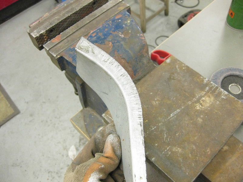 Once you grasp that it will help enormously with other repair panels. |
| |
|
|
|
|
|
|
|
|
|
This time we will shrink it instead, making the curve go the other way, now before I start I do want to make it clear that this is not easy, and will take you several attempts before you get anything remotely like a curve, but practice and perseverance is the key. And if all else fails, buy a shrinker and stretcher, it does the same thing, just alot easier and mechanically, once you grasp what can be achieved and what panels this will help you to make, then you can decide whats best for you Anyway, start with a new piece 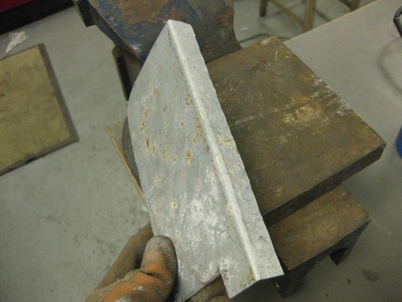 Put it into an open vice and strike down with the cross pein end of your hammer, try not to stretch the metal, just to start the pucker 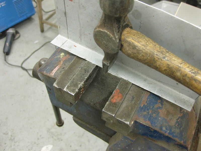 That will give you this 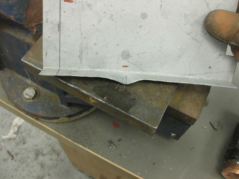 Then place it over the edge of the vice or similar 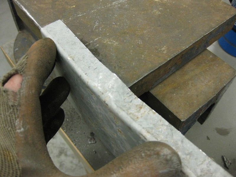 And then push it round, this raises the pucker some more 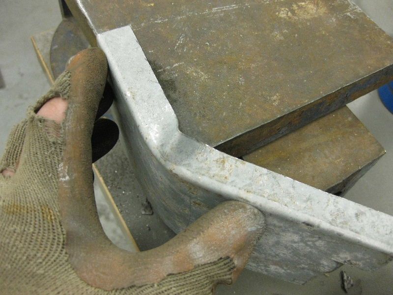 Then you need to use the flat edge of your hammer to dress the pucker in tighter, working in from both sides 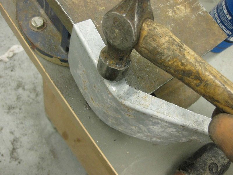 To give this, the secret is to get nice tall and tight puckers like this, not too tight mind or too tall, as you may end up folding the metal over instead of shrinking it. 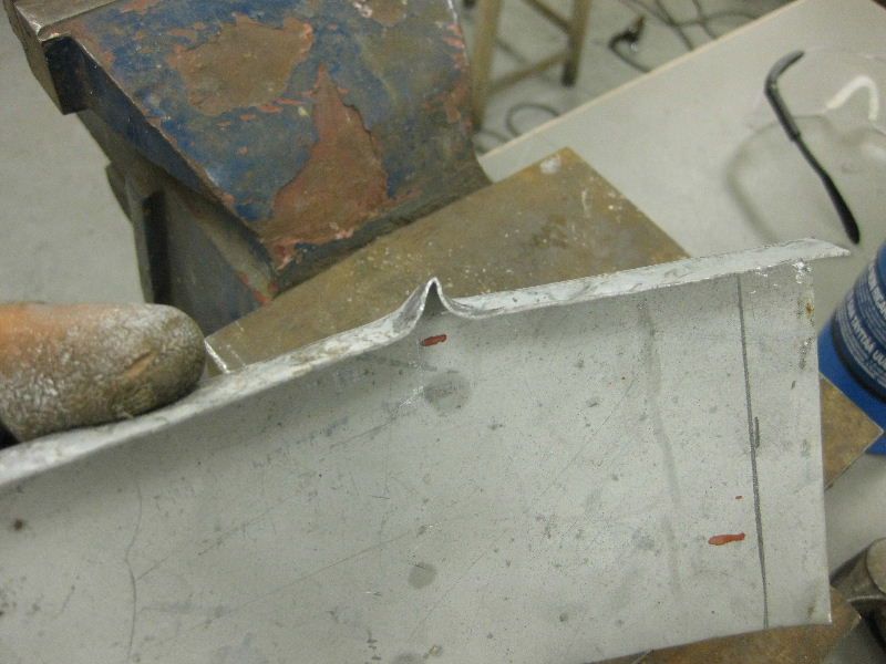 Then back onto a hard metal surface, and dress the pucker straight down, this forces the metal into itself, and shrinks it. A couple of good hard blows are best 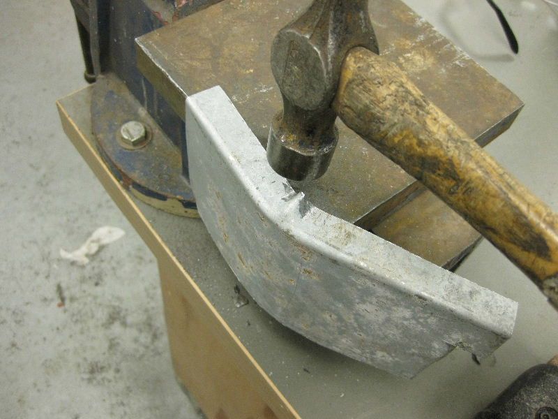 This is the result after 1 good shrink 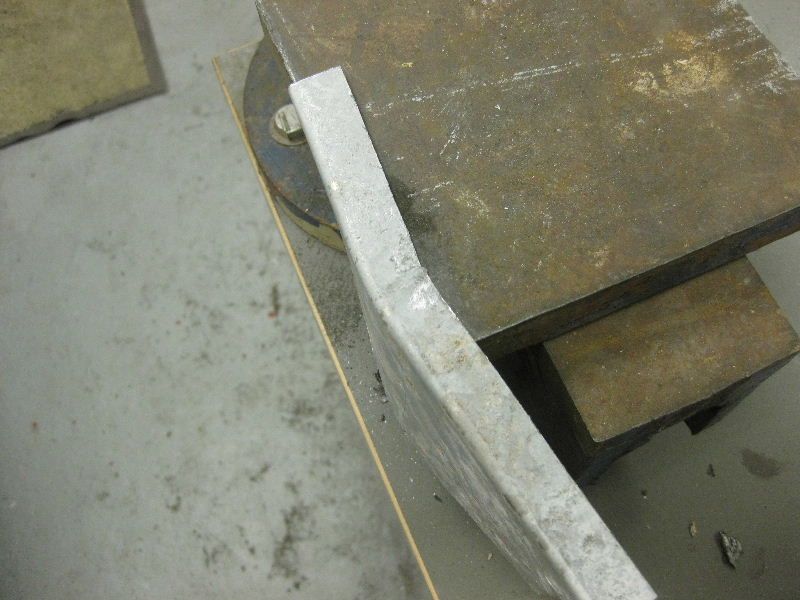 then move up and down the piece repeating the process as many times as needed 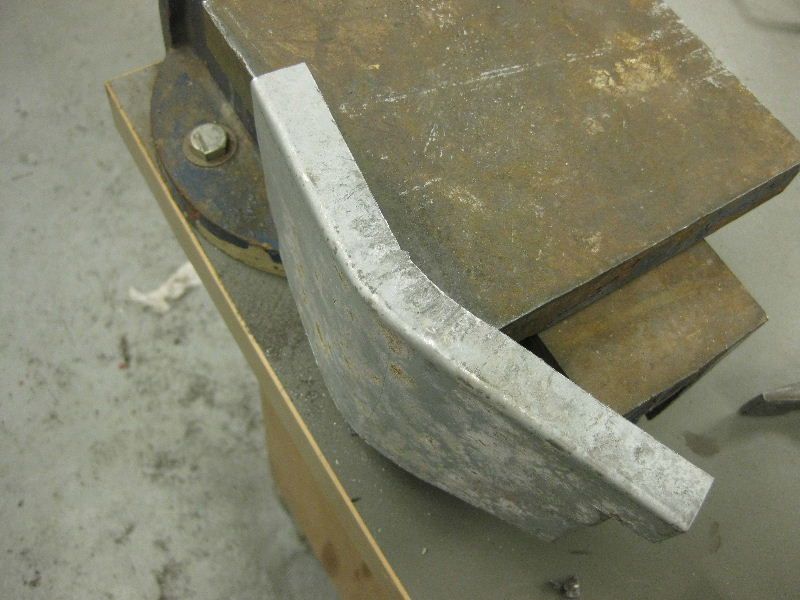 After about 10 - 15 minutes you should have something that looks like this, the wrinkles can be further dressed out, or a quick flash over with the Flap disc will help 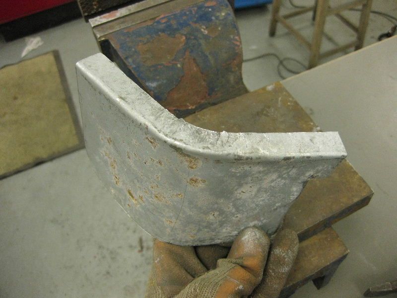 You can see that this could easily form the end of a sill repair section or similar As I said this is not easy and is likely to cause many hours of frustration before you get the hang of it, unlike stretching which gives almost instant results. Fortunately stretching is the more common type of manipulation you will need when creating repair panels. A good example of a panel using these techniques would be a wheel arch repair, you can create a wheel arch lip using these methods, and once you have the lip into shape, you can add more sections to make up the rest of the arch. |
| |
|
|
|
|
|
|
|
After re reading the thread I felt a little further explanation re the wheelarch would be in order, as this is a very common repair needed to our Retro cars Don't get me wrong there is no substitute for a proper arch repair panel, but if you cant get one, or you only need a small section then this might help I have done a drawing showing what I meant On the left is a typical wheel arch profile, and on the right, how it could be broken down into sections, that could be made using the shrinking and stretching methods. I have joddled the joints to make it a better and stronger and easier job to weld, and ultimately easier to grind flat 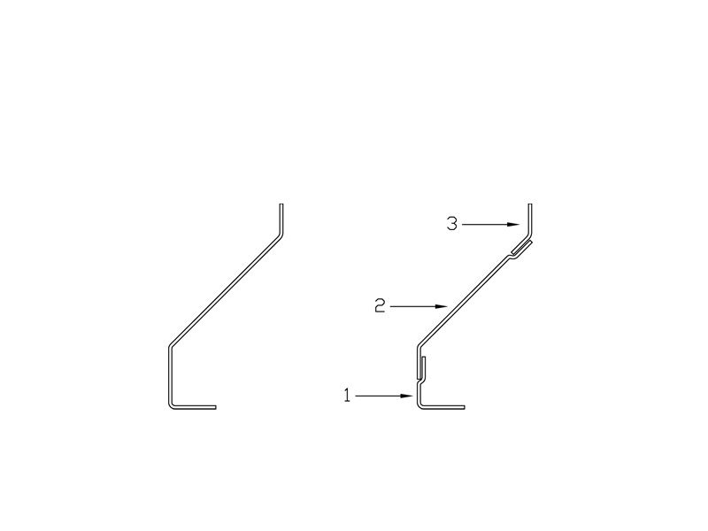 So starting with an angle section for part 1 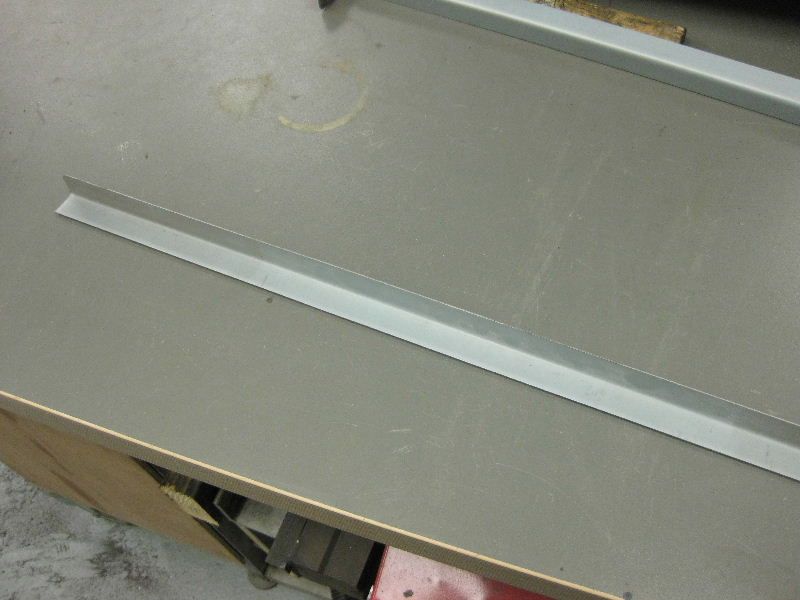 But this time for ease I am going to use my Shrinker / Stretcher 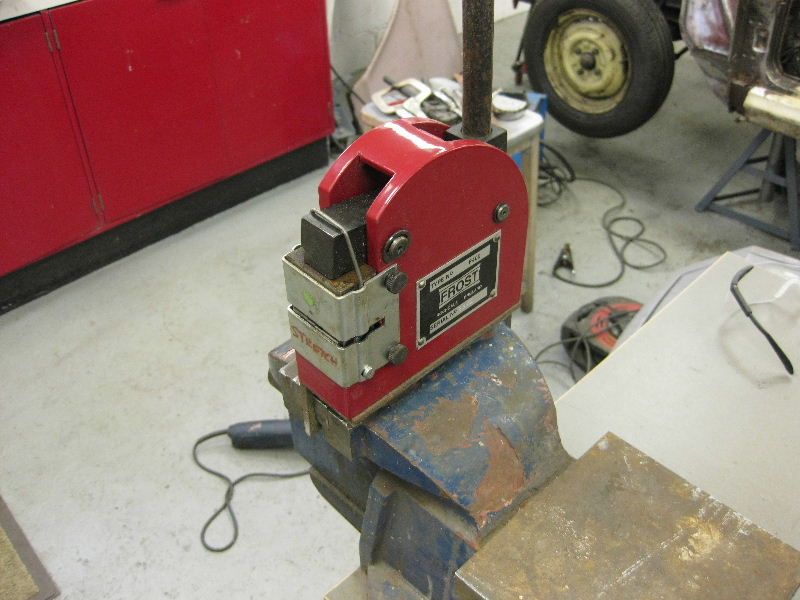 The angle goes in like this, the secret to using these is not to put the piece too deeply into the jaws, just try to stretch the first 10-12 mm of the piece, you will get much better and quicker results, than trying push it all the way in. As mentioned earlier there is a limit to the depth of flange that can be stretched or shrunk, if you stick to 20 -25 mm you should be okay 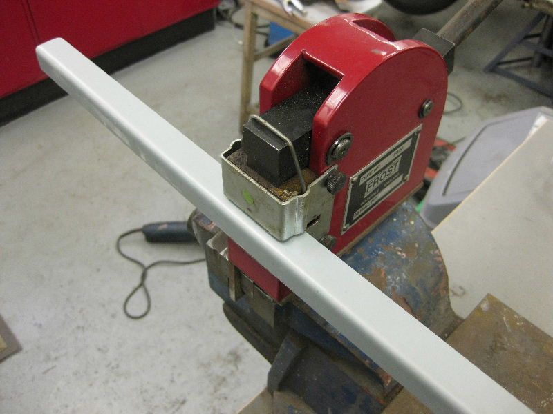 Then pull the lever, and stretch as required, move around the piece and repeat as necessary until you get the shape you want 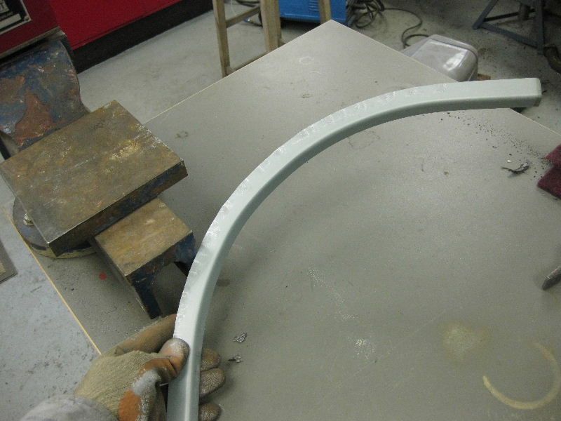 Then you need part 2 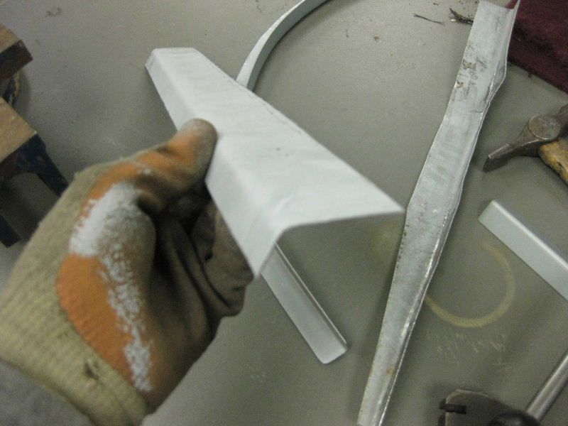 This time the jaws are swapped over for the shrinking operation 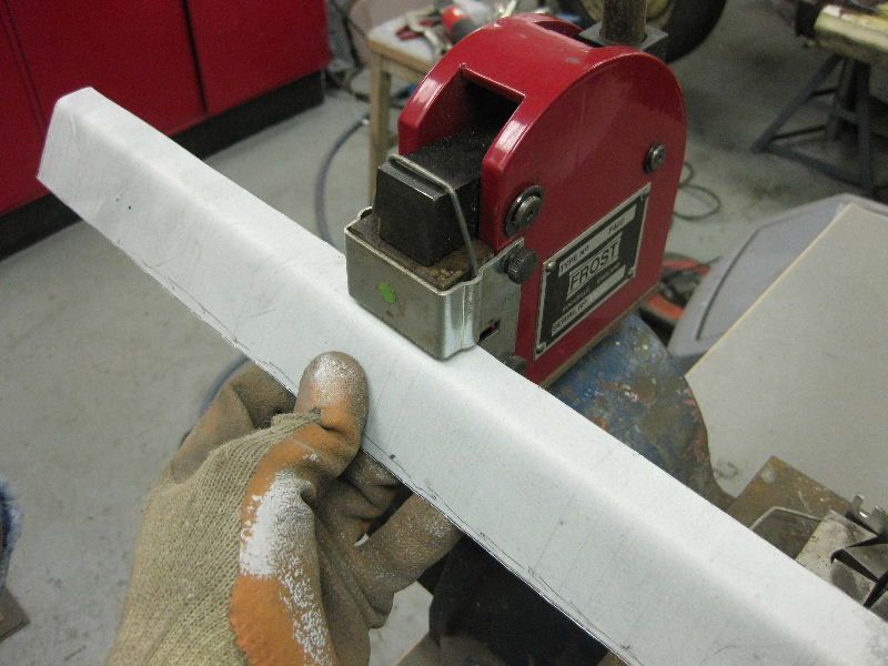 And again repeat until you get the right curve. 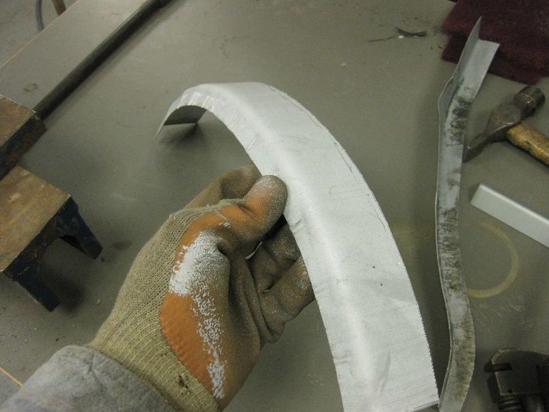 As most wheel arches also curve in wards as they go down, then part 1 may need to be shrunk in to suit, so back it in goes and work on its other flange 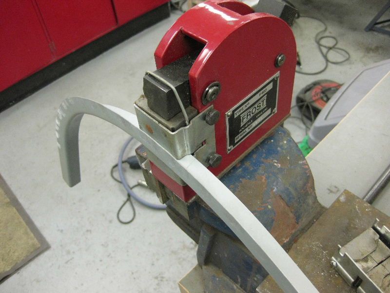 you get this, not really sure if you can see it very well from the picture, but as it curves around the arch, it also curves back in front and rear. Part 2 is much harder to make follow this shape so if necessary you may need to make part 2 in smaller sections, or even cut it in places, but for this demo, I made my part 1 suit my part 2, hopefully you will get the idea 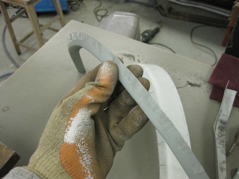 Offer the 2 parts together and tweak then until they follow the curve you need, and match each other 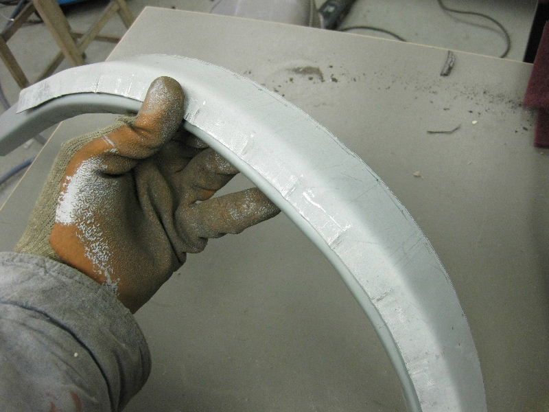 Once happy with that Joddle the edge of part 1, you can just see my air joddler to the left , they are a great piece of kit, much easier on the wrist than the hand operated ones. 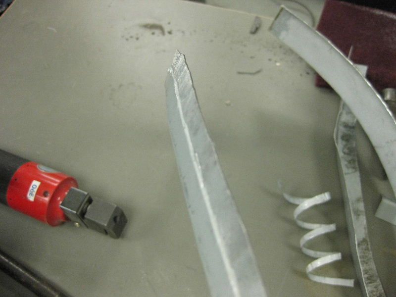 Then trim part 2 as needed and offer them together, with any final tweaking as needed 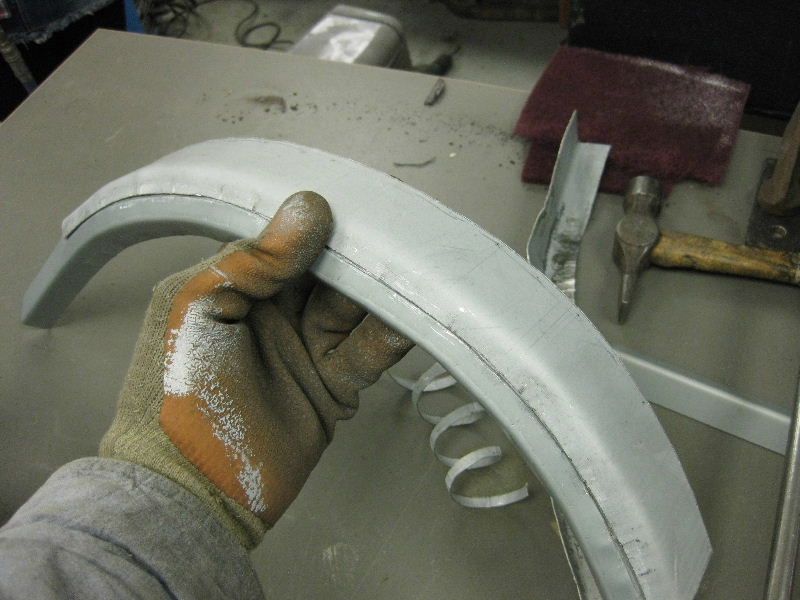 Then again for ease I spot welded them together, but obviously any type of welding will do 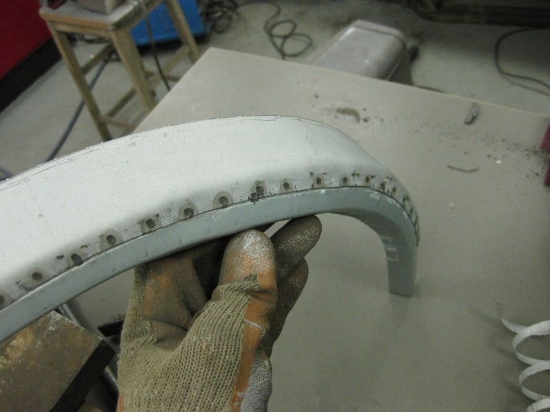 Here you can see the benefits of joddling the joint, all that needs now is a bead of weld, then grinding off, and as it is on the flat surface it should be straight forward enough, and nice and flat when you have finished 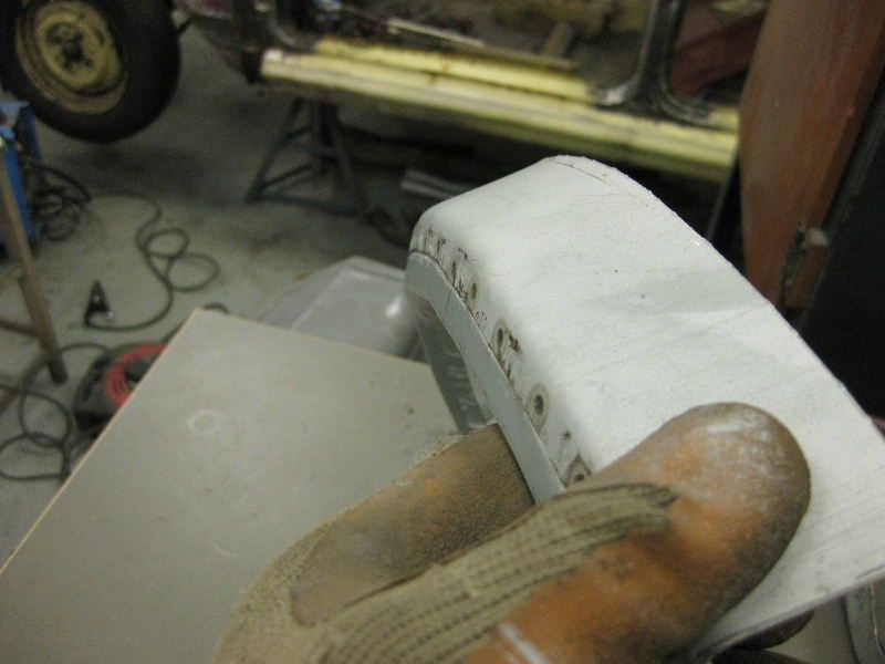 And the view from inside, a bead of seam sealer once it is welded should be all you need 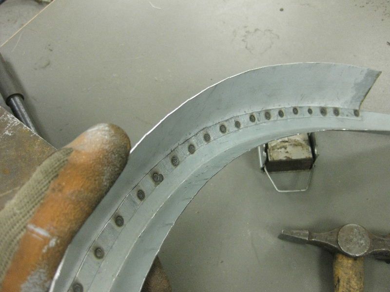 I did not actually get as far as making part 3, but I am sure you get the Jist of it, in most cases that part may not even be needed, I always try where possible to join arches along the line of part 2, as this helps to minimize distortion,makes it easier to clean off, and means you don't have to spread filler all over the whole side of your wing to try to blend it in Now that you know how to make an arch repair panel, I will quickly show you how I would weld one in This is a sequence of photos, from a BMW 6 Series that I am also busy with for another friend, Neil First cut out the rotten part of the arch, trying to keep the cut within the flare of the arch 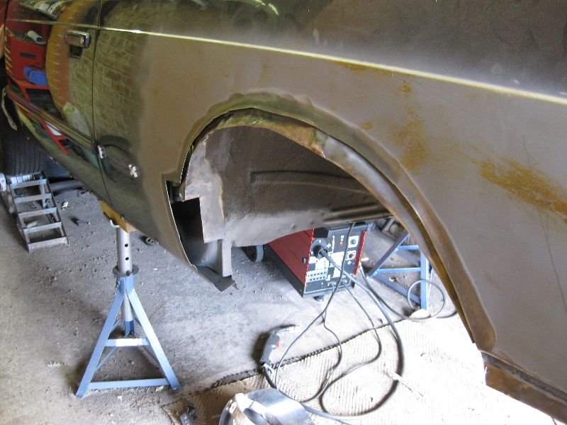 Then trim your arch down to suit 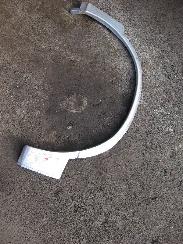 Joddle as needed 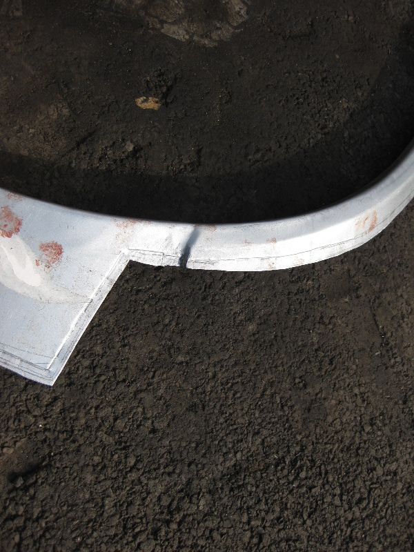 And then tack it in, make sure it is right before you start welding as once you start it will be too late to try to change it, use plenty of clamps if needed to make sure. Then lots of tacks 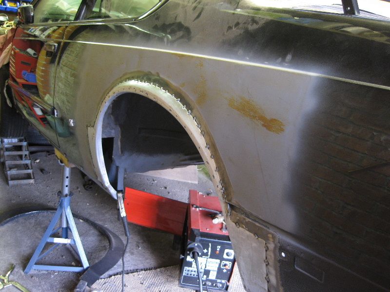 Then fully weld it, not that it as easy as that, you must only weld in 1inch bursts, and move randomly over the length of the arch doing so, the tip is to prevent too much heat build up, or else you will end up buckling the rear wing, and then have to spend hours filling it to try to get it flat again, so little at a time and well spaced out, leaving it to cool between welds if needed 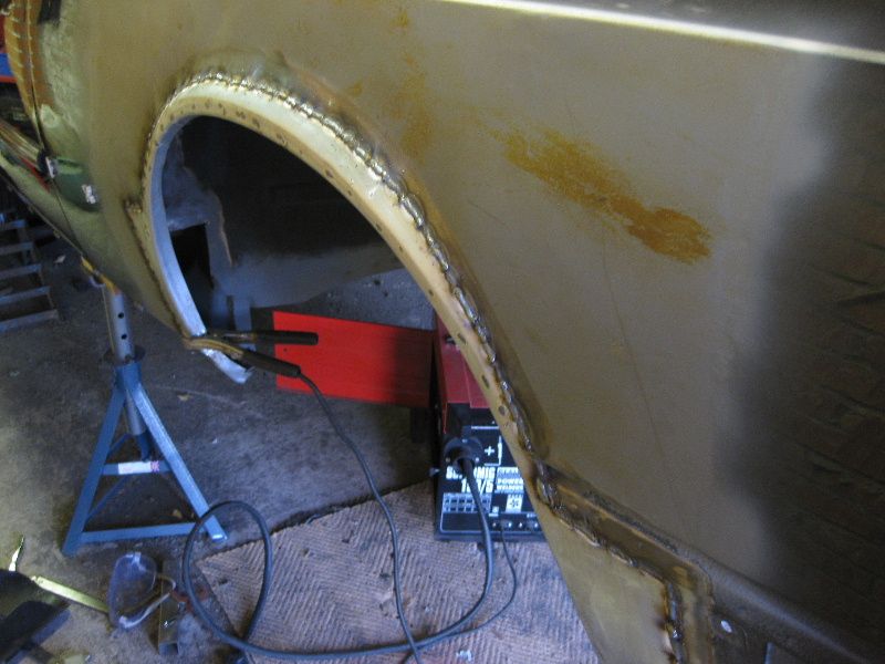 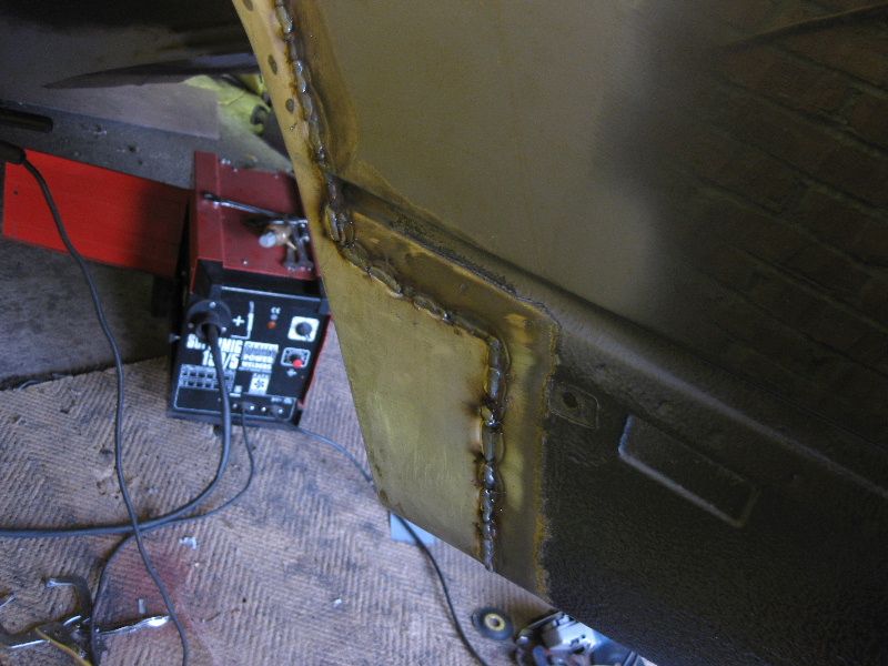 Then as before grind off using the edge of a grinding disc to start with to take the tops off the welds, and then a 40 grit flap disc, but again you have to be careful not to concentrate too much attention on 1 spot at 1 time, as even grinding can cause heat distortion and all being well you should finish with this 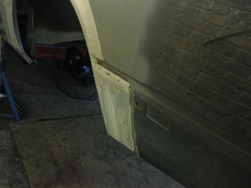 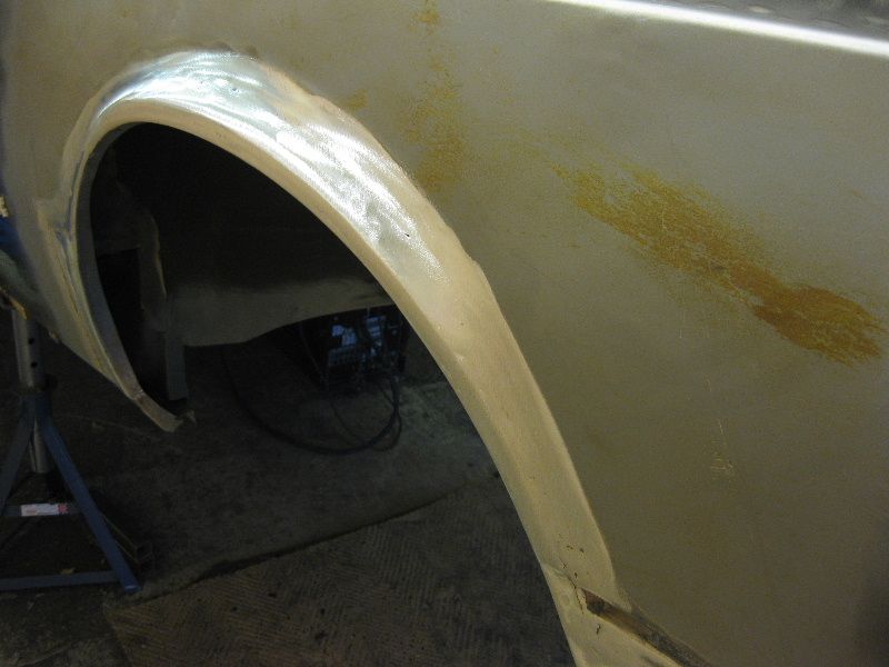 Just a light skim of filler should now see that looking just right |
| |
|
|
|
|
|
|
|
Once the battery tray was removed, it became clear that the inner wing was going to need some attention too 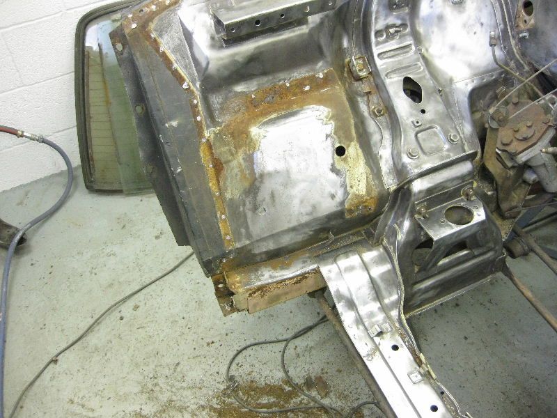 So a repair panel is going to be needed, as this could be seen from both sides, I decided that a butt jointed repair would be the best option So clean up the wing and cut out the rot 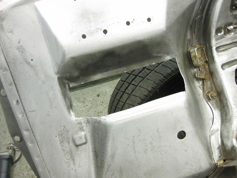 offcut of metal 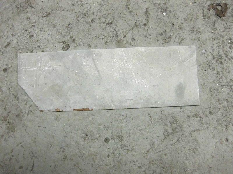 Radiused bend needed so bit of tube in the bender 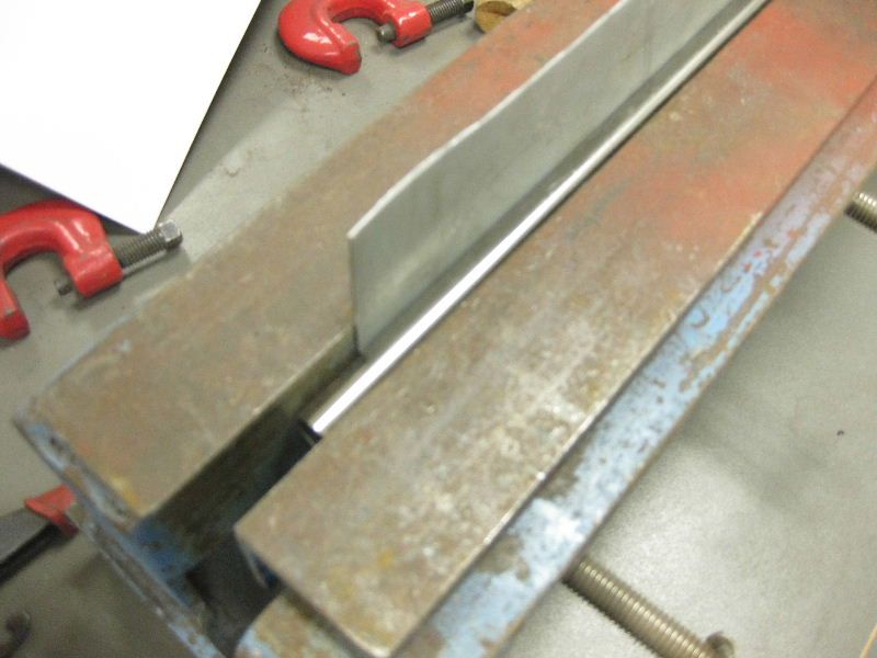 A bit oversized but will be trimmed 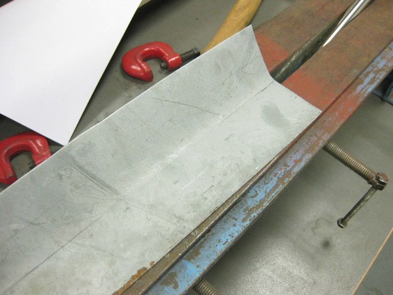 Trimmed and offered up 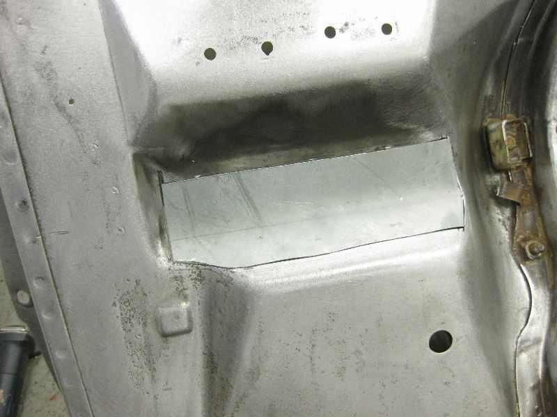 and Tacked in place 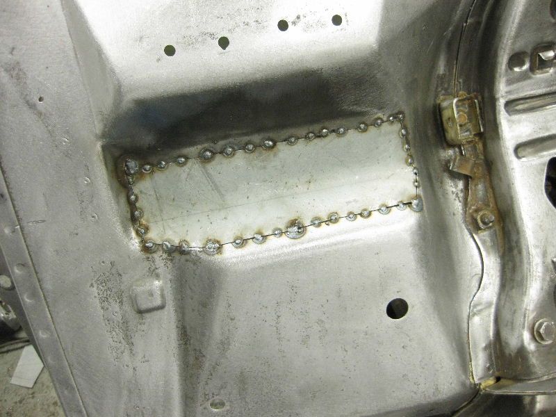 View from the rear, you must ensure good penetration when carrying out butt welds that will be ground off later 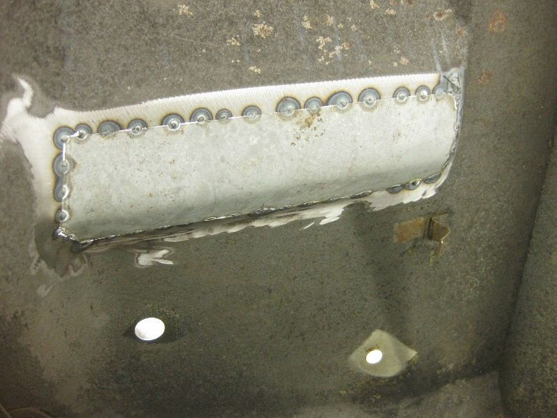 Not sure if its really a tip or not, but you really have to get good penetration when carrying out butt welds, so you really need to know your welder. to set up my welder, I keep turning the power and wire speed up until I start burning holes, and then I back the power setting down 1 notch, and adjust the wire speed until you have a nice steady weld, without spitting stuttering or burning back into the tip. When butt welding 1mm steel, you really should be expecting to burn through, if not you don't have penetration, but this should be after 3-4 seconds of continous welding, so here is what I do First of all you need plenty of tacks, and the patch must fit well, and be level, extra time spent getting this right will pay off. Then I will try on a scrap piece, perhaps as the weld starts to flow and get hot it will start to burn through after 15mm of travel, so then I only weld for 10mm, and then stop for 0.5 second, then weld another 10mm, then stop for 0.5 again, and so on and so on, just stopping for that 0.5 second, gives the metal just enough time to cool, without going cold, to allow you to continue without burning through. and if your tacks are spaced about 20mm apart then you stop and start on a tack. Then move around the piece, welding between other tacks, this stops the piece or the surrounding metal distorting with the heat. all being well you should finish with this All fully welded 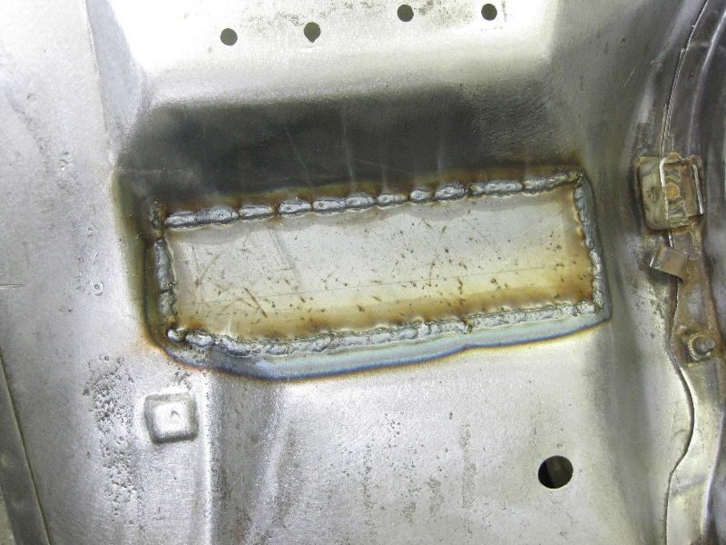 Check the rear for penetration 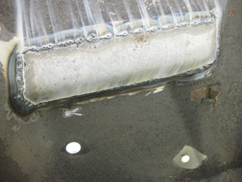 Now grind off the rear with the flap disc, it does not need to be perfect as primer and paint will cover it later 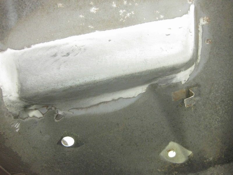 But more time needed on the front, again grind with 40 grit flap disc, then 120 grit Roloc, then Brown scotchbrite Roloc, then 40 grit DA disc, the DA disc just helps to smooth and even everything out, and nicely rounds all the edges 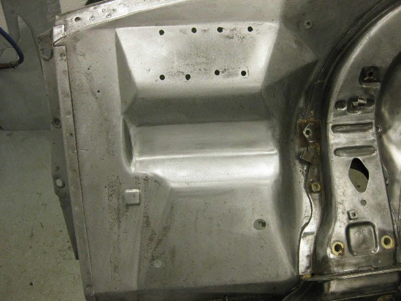 |
| |
|
|
|
|
|
|
|
|
|
I have been asked by a few people about where to get the copper blocks from, I have probably mislead people slightly by calling them blocks, when they are in fact copper flat bar, the one I use if 60mm wide x 6mm thick x 150mm long. You should be able to pick something up from your local big machine shop, or Autojumble, alternativley I have just seen this add on Ebay, they would do just the trick cgi.ebay.co.uk/Copper-Flat-Bar-50mm-x-10mm-x-100mm-Long_W0QQitemZ180374359174QQcmdZViewItemQQptZLH_DefaultDomain_3?hash=item29ff264c86I also use a thinner peice of copper plate approx 50mm wide x 2mm thick, this is useful as you can bend it or roll it into shape if you need to |
| |
|
|
|
|
|
|
|
Had to repair a motorbike exhaust for another friend, straight forward enough, but 1 piece was supposed to fit inside the other and I did not have a piece of tube, the right diameter for the larger bore So Took one section of the tube 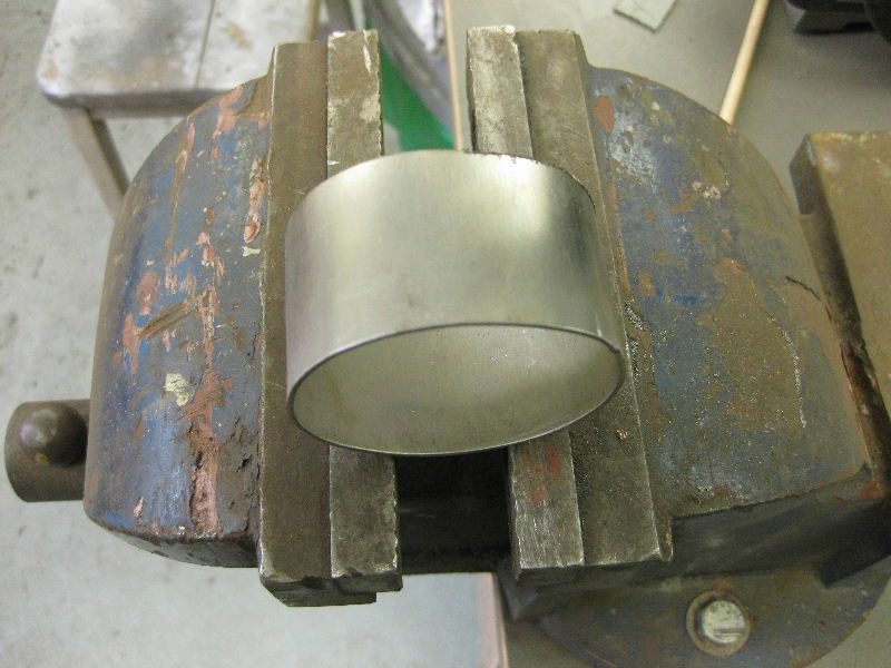 and cut 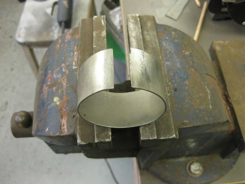 Open out to the new diameter and clamp in place with a piece of rolled copper underneath, but make sure the copper is clean, not like this piece, you will see why later 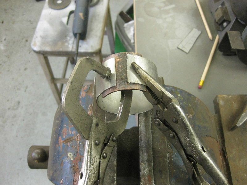 Then lay 2 tacks down 1 at each side 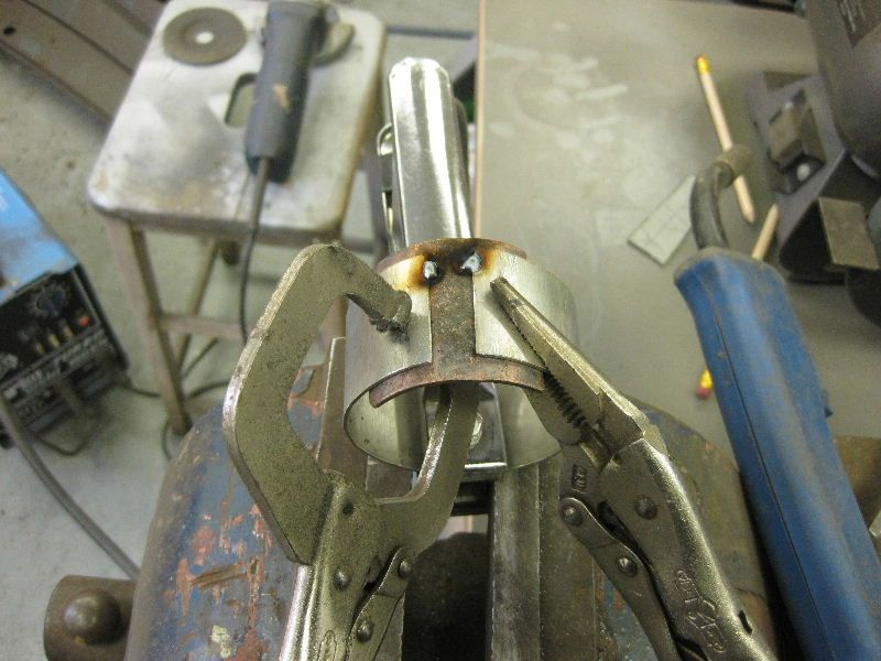 Then join up, just weld straight across the copper  then repeat at the other end, joint at 12 mm so quite a gap to fill 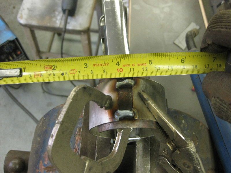 Then weld across in a zig zag fashion starting from one end and working down, the idea is to try to keep a continuous and hot weld for good penetration and no porosity Photo taken whilst it was still hot 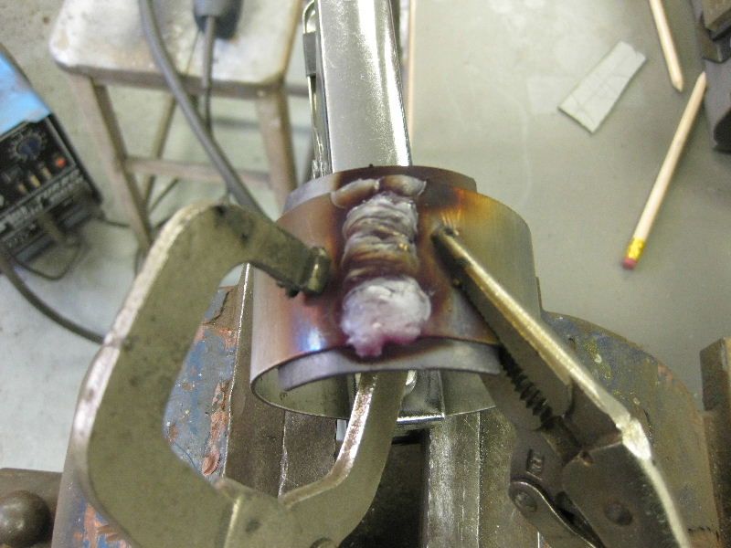 Remove copper, I had to get a chisel between to split them apart in this instance, the contamination I mentioned earlier had attached itself to the weld and the copper, but a couple of swift blows and it was off View from outside, large weld but will clean up if needed 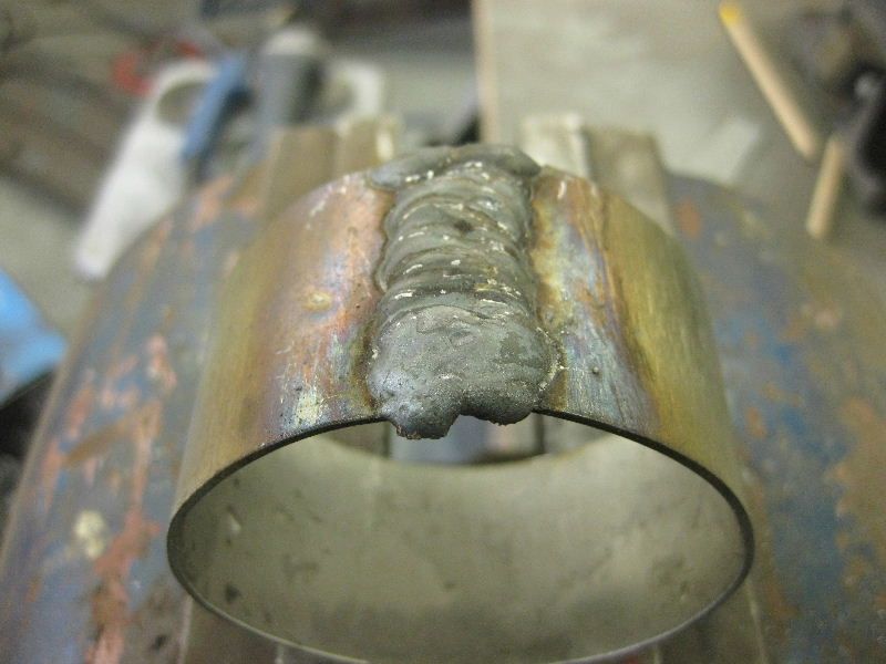 And more importantly view from the inside, a quick going over with the flap wheel on the die grinder will soon have that smoothed out 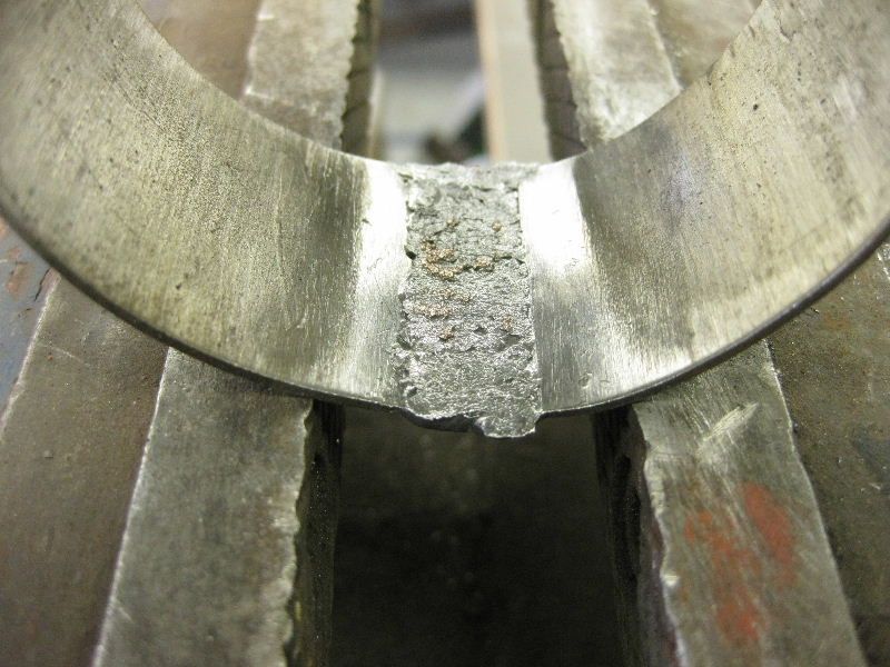 I could not have done it like that without the copper block |
| |
|
|
|
|
|
|
|
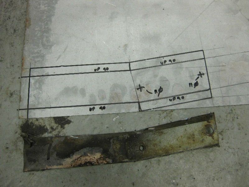
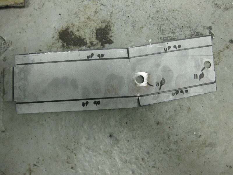
I have shown you how to make these parts, but never explained how you measure and mark them out, I apologise in advance if I am covering stuff that you already know, but I thought it would be worth clarifying it What you have to remember when working with metal is that you work with the inside sizes, and then when you fold a peice up its outside sizes are 1 metal thickness bigger at each bend. For example if you were to mark 2 lines at 50 mm apart on a piece of 1.5 mm steel and then fold both of those lines up to form flanges and then measured it, it would measure 53 mm outside. I will show you with some pictures, it is one of those things that once you can see it it is obvious So say for instance we wanted to bend up a piece of angle in 1.5mm steel and the outside sizes of the angle are to be 25mm x 30mm  Then the inside sizes would be 23.5mm x 28.5mm  and they are the sizes you would mark on your sheet, obvioulsy if the material had been 3mm thick, then the sizes that you marked would have been 22mm x 27mm As your piece starts to include more bends, it becomes a little more complex, in that you have to take off 2 metal thickness, this really insn't any different than before as it is 1 thickness per bend, but per direction also Again a picture might help Say we wanted to bend up a chassis section 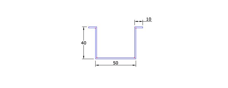 The inside sizes would be  Note how this works when you bend the last 10mm flange on, you still work to the inside size, but as it is only 1 bend then you only take off 1 x metal thckness, but also note that to achieve the overall width of 50mm you have to mark and bend the width at 47mm The flat pattern for this chassis section would be as follows 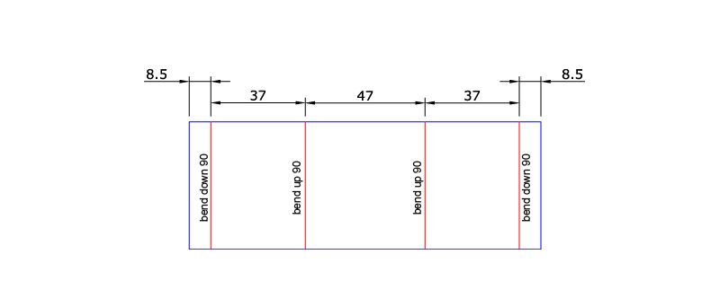 Hope I have made that clear and sorry if I have gone over something that you already knew |
| |
|
|
|
|
|
|
|
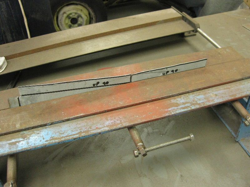
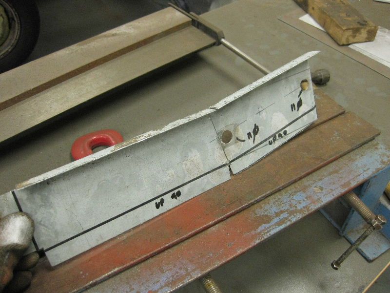
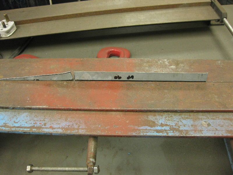
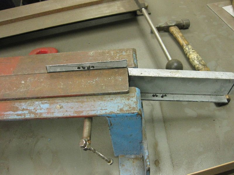
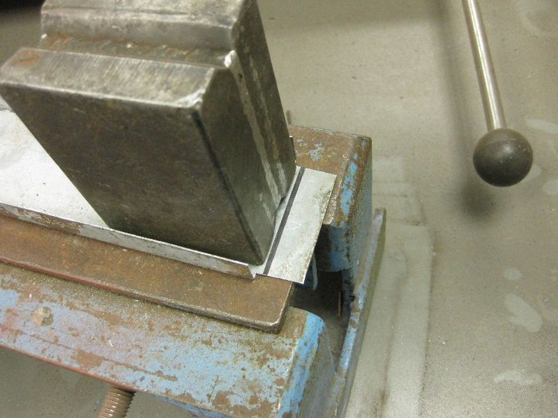
Awesome work. Can you offer some advice on how to make a piece for my Vw splitty. It is basically this cross section - 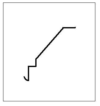 And goes here - 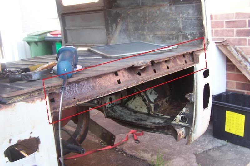 The folds are quite small at the bottom, about 10-15mm and the strip is 1800mm in length. It also has the radiused fold on the bottom for the rain seal to sit into. The centre will need chopping about but I would love to be able to make this. Any advice? These are the approximate, but fairlly accuarate measurements and ahd lost onf the folds at the base of the sloping piece.  Hope this helps and thanks for your advice so far Dubwarrior2 - Your piece first, it is a bit more tricky than my first sample as the bends are so small, I can honestly say that you might be better off getting a local sheet metal place to knock all the straight bends up for you, and then just leave you to knock the radius on last. But here is my attempt at it anyway, as I said, it is much easier on a small section like this then on a full 1200 long piece Start with steel 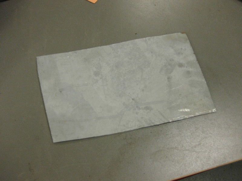 Mark out 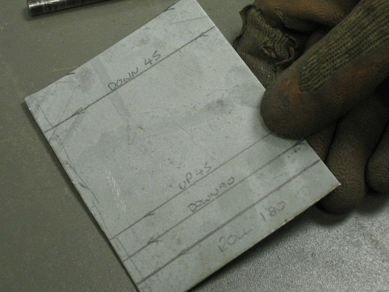 Create first bend, this is the radiused end first 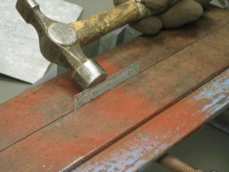 Over 90 degrees 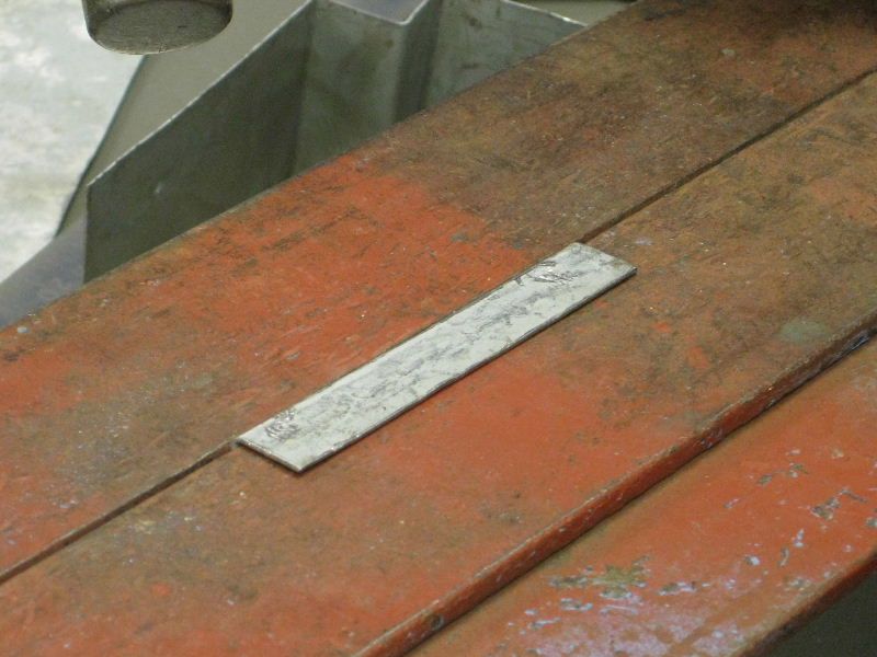 Then reposition for the next bend 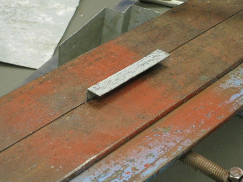 But the bend is too small to get the hammer in. 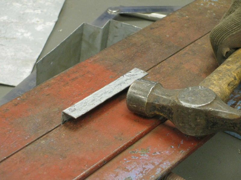 You could try knocking it over from there, but you will more than likely damage your first flange, the alternative method is to drift it over, I used the copper block, but you could use anything, even a piece of wood if necessary 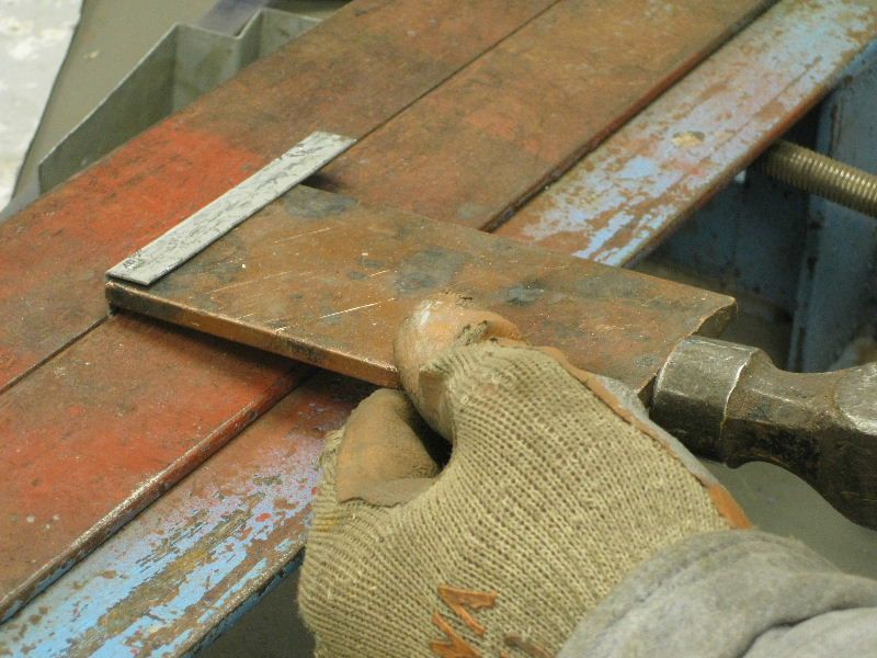 And then gently tap it over, moving along the piece as you go 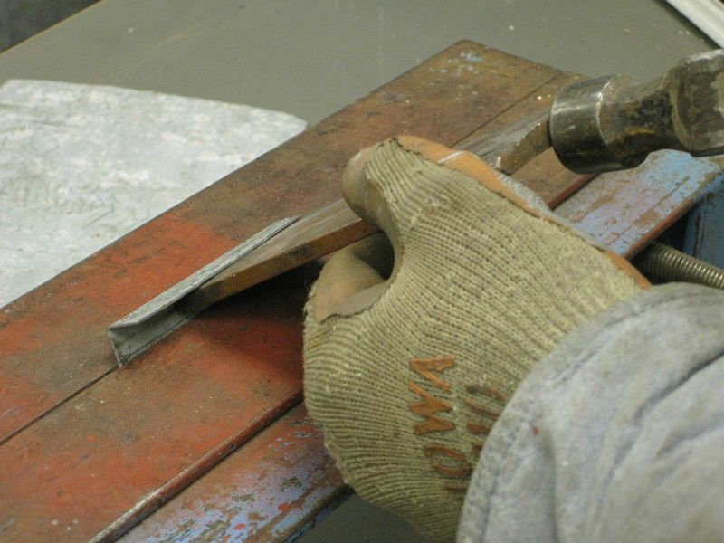 Until you get it over far enough to get back in with the hammer 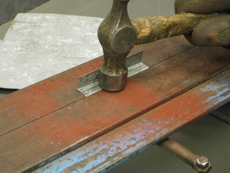 Again relocate for next bend, again need to use the drift 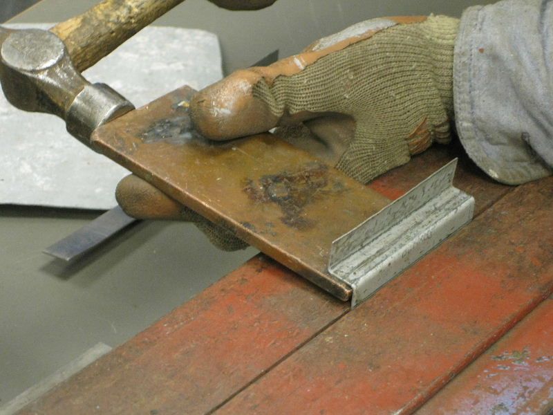 And over 45 degrees this time, or whatever the angle is 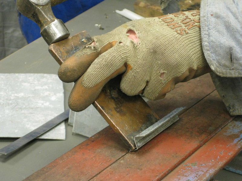 That gives you this 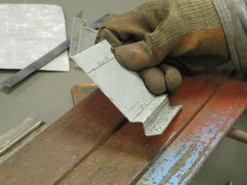 Then relocate for the last bend this is much more accessible and can be knocked over with the hammer, 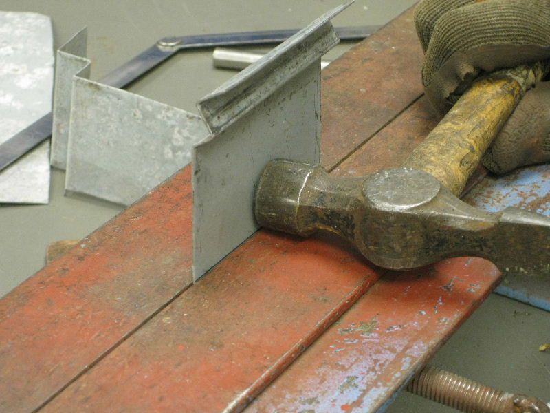 some hand pressure on the top edge helps to take it over 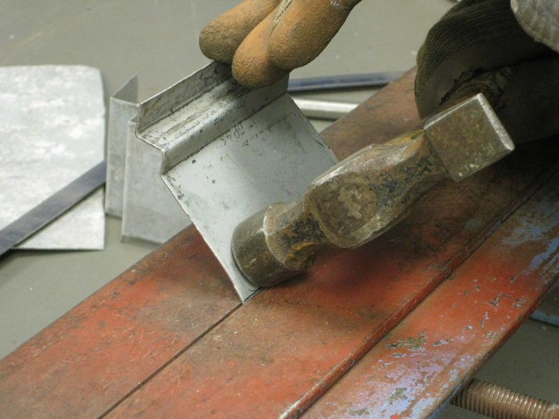 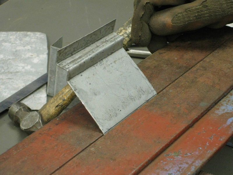 To this, almost there 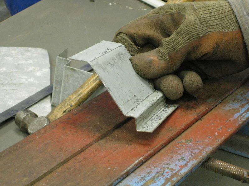 Then just need to create the radiused bend on the end, I was struggling to find anything 8 mm dia, so just used this drill bit, but it would be much better to use something smooth, like some round bar. Anyway, clamp the drill to the piece 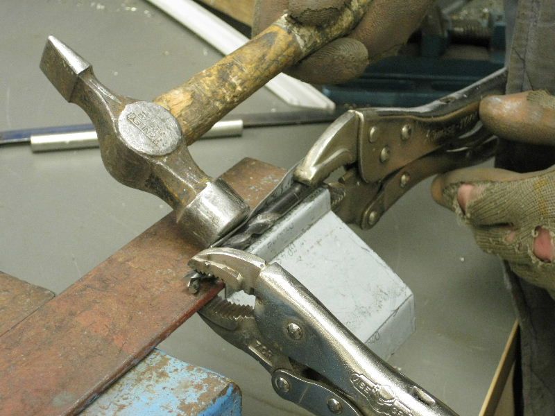 And dress it over 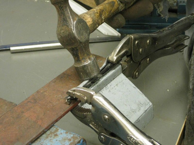 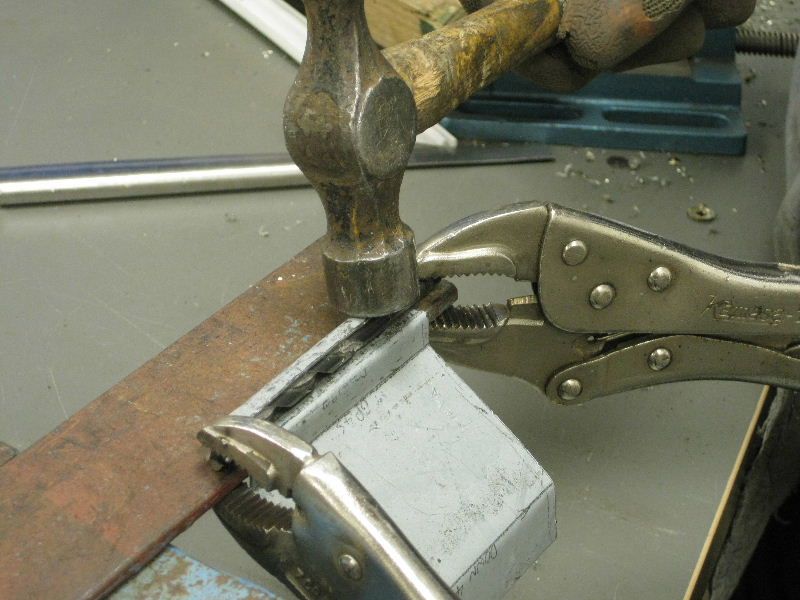 and there you have it 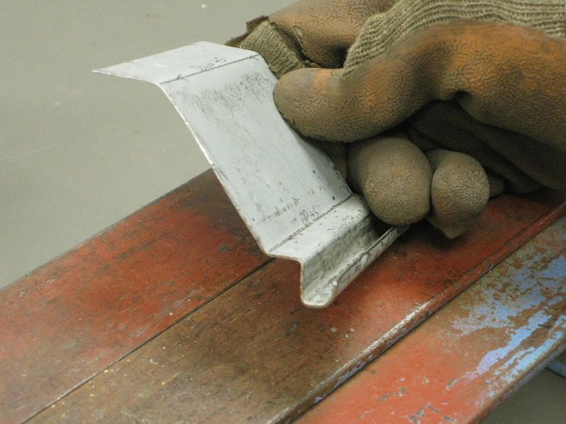 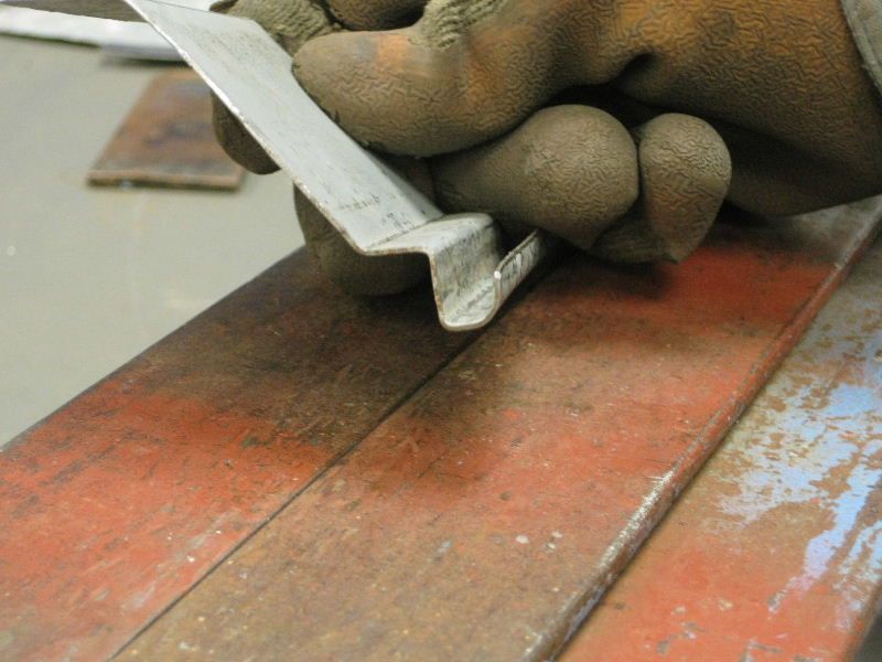 Hope you like it |
| |
|
|
|
|
|
|
|
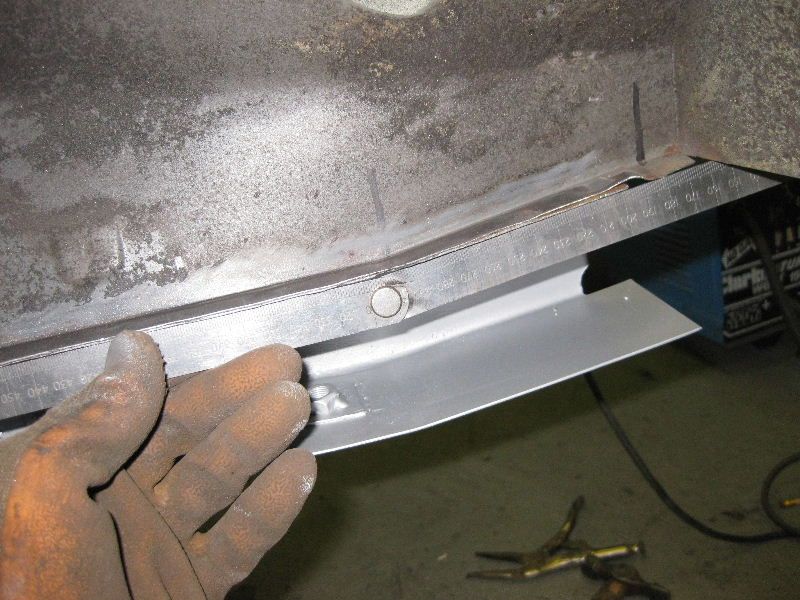
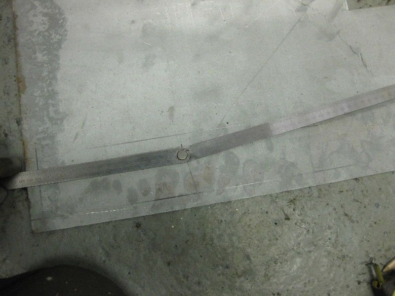
Hi there, sorry to make this into a question and answer thread but: I need to make a new engine sump and I want to weld it as little as possible. after a bit of thinking I made a rough diagram of the add on to the original sump pan: 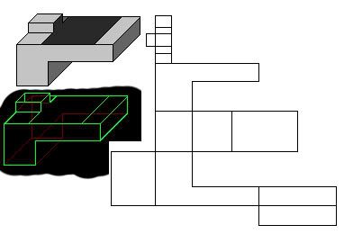 I want it to be simular to my current sump: 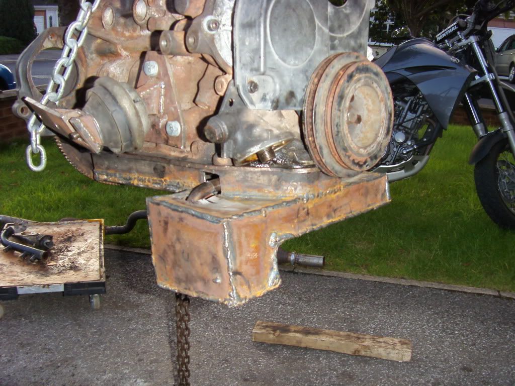 Would the bend lines be best, or too akward, or theres a better way??  Your flat pattern is about right except I think your bottom right hand section looks too large 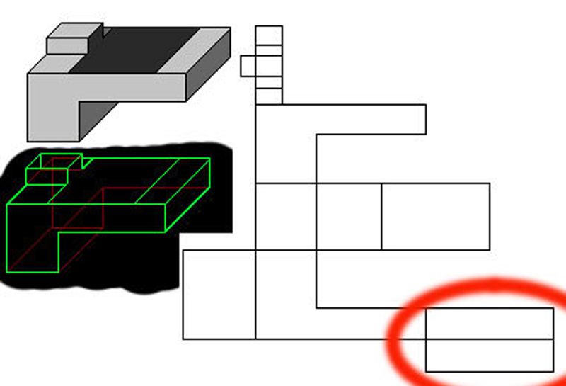 Whilst you could go ahead and cut it out like that, it would be quite awkward to do and then even more difficult to bend up So I would propose breaking it down into these sections instead, the centre section being just one piece 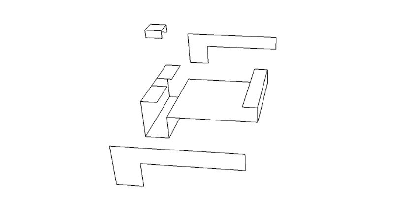 That way they are just 4 x rectangles with some notches, much easier to create and a whole lot easier to bend up, not sure if you planned on bending it up your self, but as you will need to use something quite thick, you would be best off getting a local sheet metal place to bend the centre section up for you, any company with a half decent press brake should be able to achieve that centre section in one piece, just leaving you to weld the ends and the small cap on top Hope this helps |
| |
|
|
dubwarrior2
Part of things
  "Open up, its the filth"
Posts: 576
|
|
|
|
|
For the copper, to prevent welds coming through, I have used flattened copper piping. Just squeeze it flat in a vice and it can be bent into all sorts of shapes for those hard to reach areas.
|
| |
|
|
|
|


