jonomisfit
Club Retro Rides Member
Posts: 1,787
Club RR Member Number: 49
|
|
Jul 12, 2020 19:27:41 GMT
|
not much exciting to see today. I spent ages getting my head round the multi function switches for the steering column. Lights, wipers, etc. i'm all OK with, but can I undertstand the indicators? Can I curse word. It just doesnt seem to work / make sense to the point of which i'm wondering if the indicator switches are knackered. I've got a wiring diagram but the only time I can get a conection though the indicator switches is when the hazards are on. The diagram shows that it should get a connection through to earth when the hazards arent on, but it doesnt. I even dug out a 12v power supply and hooked it up in case there is a relay / solid state switch in there that needs power to enable. But to no avail.  P1030950 P1030950 by jono_misfit, on Flickr I'm quite peed off with it, so may replace the functionality via either steering wheel mounted push buttons or toggles in the dash. After a while I moved on to something more productive and started on the engine bay loom work.  P1030951 P1030951 by jono_misfit, on Flickr The more i'm doing the more its remining me this is wholly excessive :-) |
| |
Last Edit: Jul 12, 2020 19:30:42 GMT by jonomisfit
|
|
|
|
|
|
|
Jul 12, 2020 20:03:10 GMT
|
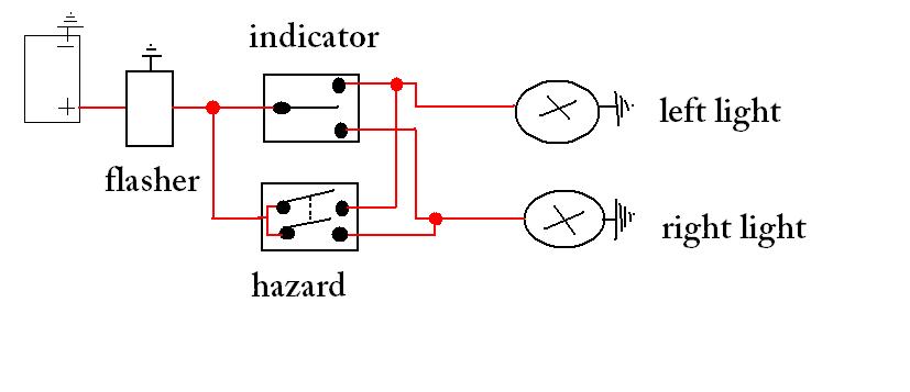
I believe you have enough knowledge to sort it so something strange is happening, If you have an electronic flasherunit this should be the basic diagram (without ignition lock, fuses ect)
Peter
|
| |
|
|
jonomisfit
Club Retro Rides Member
Posts: 1,787
Club RR Member Number: 49
|
|
Jul 12, 2020 20:28:41 GMT
|
Thinking on it the only thing I can think of to check is if there is a resistence change with the indicators rather than switching, but i'm not convinced. The swtich unit does look like its been outside a fair bit.... Having a quick look on car builder solutions, I can buy a basic indicator stalk setup, with main beam and horn, for £20, so I may well get this. It'll save me ages of messing about, and I can always put a plug on it so if I can change it out in the future if needed. www.carbuilder.com/uk/heavy-indicator-dip-horn-stalk-assembly-500mm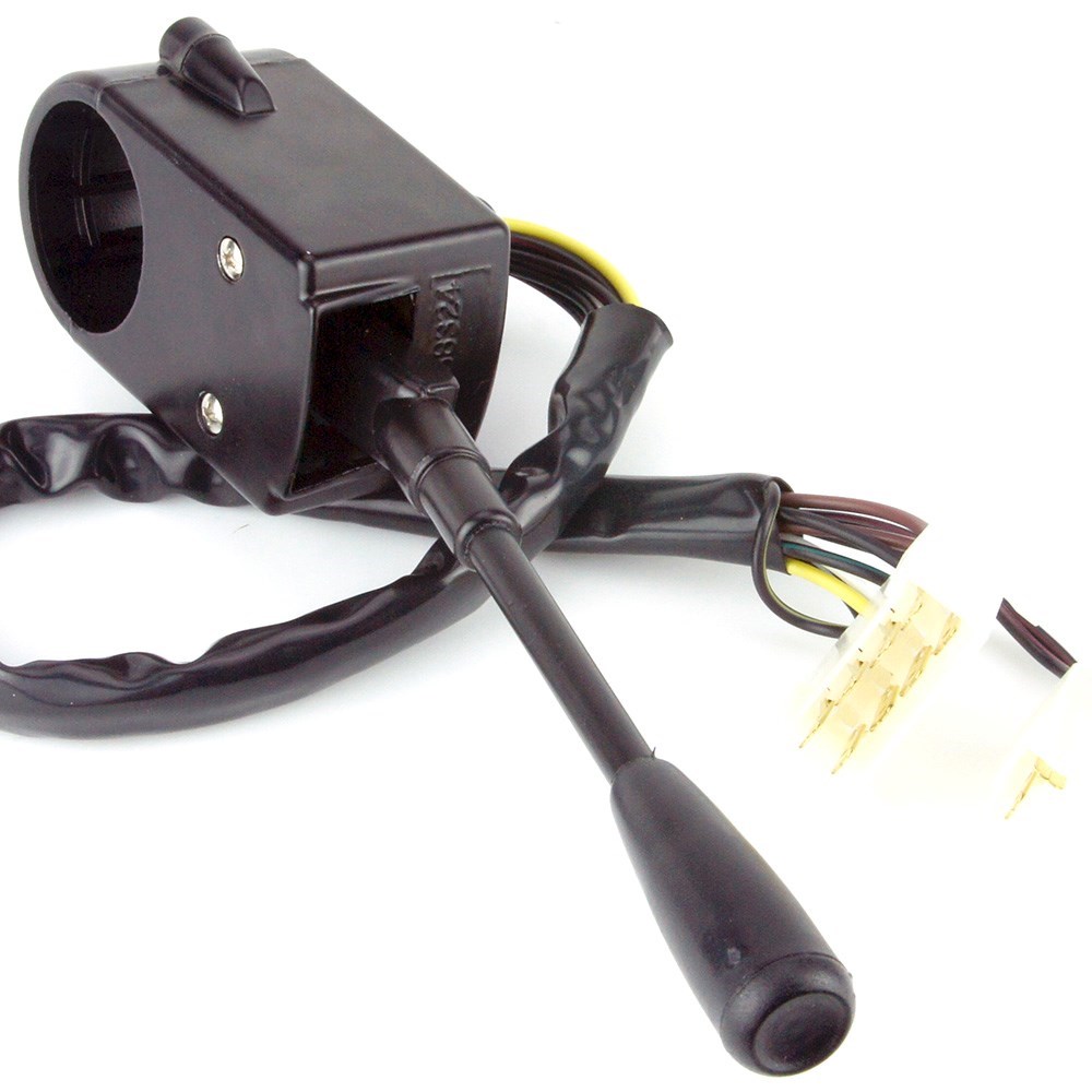 |
| |
Last Edit: Jul 12, 2020 21:43:39 GMT by jonomisfit
|
|
|
|
|
Jul 12, 2020 21:16:54 GMT
|
picture did not get threw
|
| |
|
|
|
|
|
|
|
|
Are you testing with all The lights plugged in, and are they all good?
Simple thing, and I guess usually they flasher faster if the whole circuit isn't there, but you never know.
Is the flasher clicking at all?
|
| |
|
|
jonomisfit
Club Retro Rides Member
Posts: 1,787
Club RR Member Number: 49
|
|
|
|
Are you testing with all The lights plugged in, and are they all good? Simple thing, and I guess usually they flasher faster if the whole circuit isn't there, but you never know. Is the flasher clicking at all? It was just the switch set on the bench with a multi-meter and probes. Some with a fixed 12v power supply on, some without. The flasher unit is in a separate piece of the loom and not connected in. |
| |
|
|
|
|
|
|
|
|
Indicator circuits have always been rocket science to me - even on the simple stuff like the Jowett's (then again thinking about it they are not that simple has they have traffictors which have to be wired separately) - never understood the circuits and have spent far too long on too many different cars scratching my head has why I cant see power on the meter but the supply to switch is live etc - Now I don't bother with the meter testing I just connect everything up to the lamps / switches / flasher relays & then power them up for testing and other than a poor earth or a dodgy bulb holder everything tends to works correctly
|
| |
|
|
jonomisfit
Club Retro Rides Member
Posts: 1,787
Club RR Member Number: 49
|
|
|
|
|
Ideally I'd do this, however I'm in the situation ive reduced the wiring and not all is there any more.
A problem of my own creating 😀
|
| |
|
|
jonomisfit
Club Retro Rides Member
Posts: 1,787
Club RR Member Number: 49
|
|
Jul 13, 2020 20:07:36 GMT
|
I've been doodling in CAD working out how i'm goign to do the centre console. I pinched a bit more space by moving the start button and ignition switch into what used to be the dashboard change pocket. 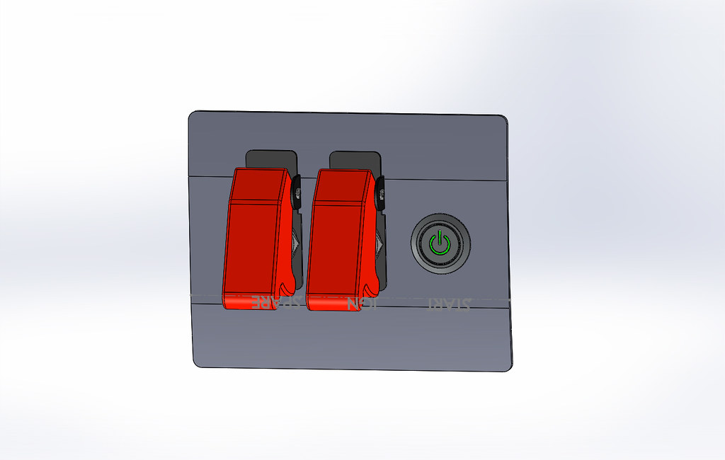 Start Panel - 1 Start Panel - 1 by jono_misfit, on Flickr  Start Panel - 2 Start Panel - 2 by jono_misfit, on Flickr which means I end up with a centre console like this.  Cosworth centre console - 1 Cosworth centre console - 1 by jono_misfit, on Flickr Fairly neat and laid out OK. Except..... when you look in the back.... thats tight. 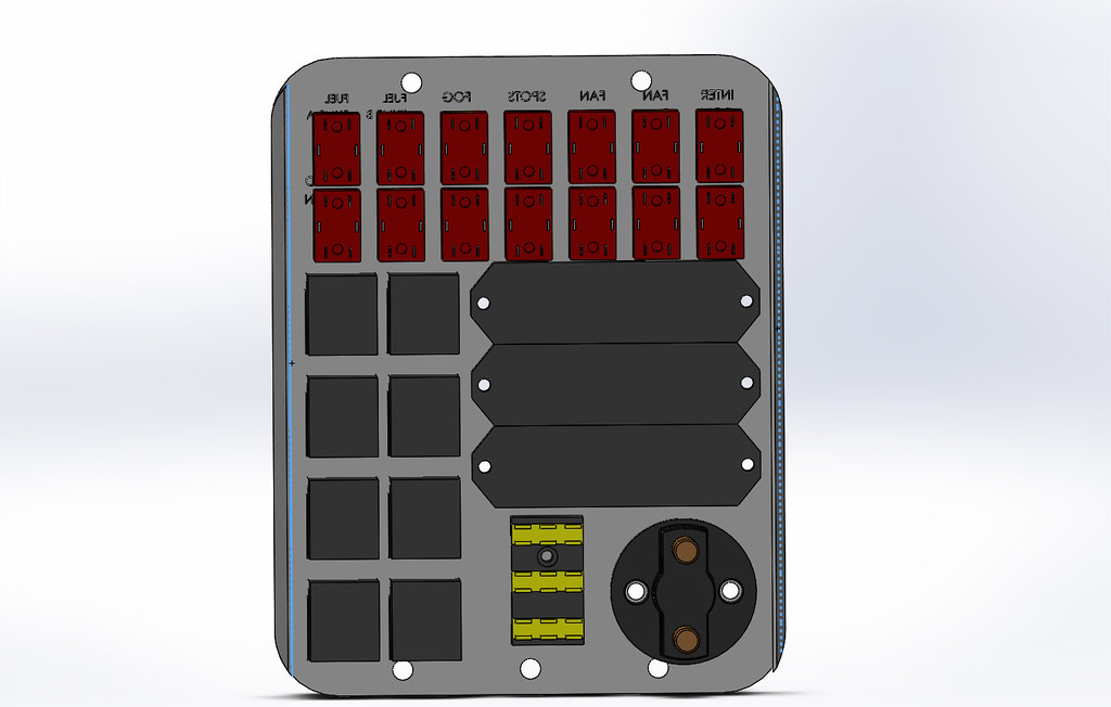 Cosworth centre console - 3 Cosworth centre console - 3 by jono_misfit, on Flickr really tight.... And thats before getting the battery leads in there, A second distribution block for earths, and.... 70+ connections needed to go between switches, fuses, relays, and to / from the car. there is no space for routing of the cables. I could have it looking like an old fashinoned telephone exchange, but i don't think its right. It needs loomed nicely. And to do that I need more space. i could move the relays to a seperate location, and I've found a few pics where thats been done. A favourite seems to be removing the glovebox and making a panel on there. But it does still mean a load of jumpers on/ off the front panel. I think i'll need to do what they did on a lot of the group A escorts and relieve the centre console section of the dash and re-make as a panel. Like Ken Blocks Group A Escort (Pic (C) ken block etc.) 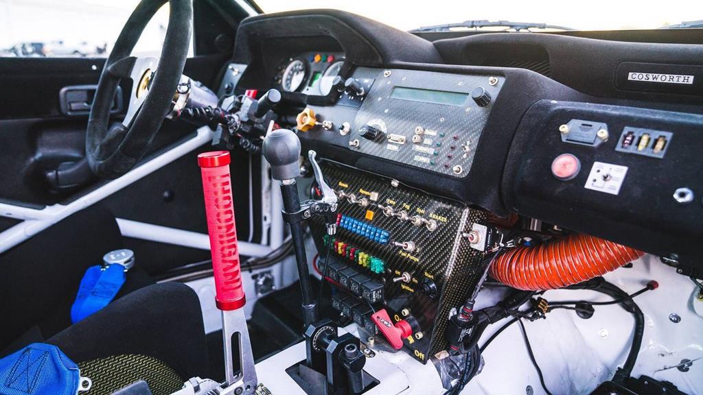 Compared with my centre console panel.  P1030808 P1030808 by jono_misfit, on Flickr I just need more real estate i think to make it work well. It's an old nackered dash I've got so its not like its worth anything. as always, will see where I get to with it. |
| |
|
|
thomfr
Part of things
  Trying to assemble the Duett again..
Posts: 691
|
|
Jul 13, 2020 21:15:55 GMT
|
|
I assume you will take the passenger airbag out ;-) ?
Thom
ps: Know the problem, I only had to route a fuel pump relay, 3 lamp relays and a indicator relay and was already fighting a sausage thick bundle of cables...
|
| |
73' Alfa Giulia Super
64' Volvo Duett
65' Volvo Duett
67' Volvo Amazon 123GT
09' Ford Focus 1.8
20' VW ID4
71' Benelli Motorella
65' Cyrus Speciaal
The difference between men and boys is the price of their toys
|
|
|
|
|
Jul 13, 2020 21:21:12 GMT
|
|
John
Where do you get the cad models for the switches and parts from or do you model them up your self?
|
| |
|
|
jonomisfit
Club Retro Rides Member
Posts: 1,787
Club RR Member Number: 49
|
|
Jul 13, 2020 21:59:27 GMT
|
I assume you will take the passenger airbag out ;-) ? Thom ps: Know the problem, I only had to route a fuel pump relay, 3 lamp relays and a indicator relay and was already fighting a sausage thick bundle of cables... Yep, the airbag cavity will be re-purposed as a trip meter mount. CAD models, it depends what I'm after. I usally look on GRABCAD and see if they have the models I need (or close too it, although GRABCAD is not always easy to find what your after), if not I just do some quick mock up models / space grabs based on the manufacuters dims. Some manufactures do free IGES files from their websites, but its usually a fairly sizeable manufactures that do that. |
| |
Last Edit: Jul 13, 2020 22:00:19 GMT by jonomisfit
|
|
jonomisfit
Club Retro Rides Member
Posts: 1,787
Club RR Member Number: 49
|
|
Jul 17, 2020 19:49:00 GMT
|
A couple more bits turned up. Including these bulkhead connectors  P1030952 P1030952 by jono_misfit, on Flickr  P1030953 P1030953 by jono_misfit, on Flickr If anyone who watches Binky thinks they look familiar, thats because they're the same as they use, it turns out they're a distributor for the connectors and I may as well buy things that suport something I like. They'll go here.  P1030954 P1030954 by jono_misfit, on Flickr may have to un-large the hole  P1030955 P1030955 by jono_misfit, on Flickr With the space to get in and withdraw the connector once it has cable in the back I think i'll have to mount it slightly inclined. Either that or patch the bulkhead and move the connector hole up... but then that ends up with space issues on the inside. I think incline it is. I continued on with the sleaving.  P1030956 P1030956 by jono_misfit, on Flickr  P1030957 P1030957 by jono_misfit, on Flickr  P1030960 P1030960 by jono_misfit, on Flickr And moved the feeds for the fan motors / controllers to inside the car with the other connections, rather than in the engine bay.  P1030961 P1030961 by jono_misfit, on Flickr Added in the additional wires for the spotlights connection  P1030962 P1030962 by jono_misfit, on Flickr I also took some measurements for the size of console I can get in if I cut out the stereo box from the dash  P1030958 P1030958 by jono_misfit, on Flickr  P1030959 P1030959 by jono_misfit, on Flickr It provides a lot more space. Which means I think this is the way I'll be going. |
| |
|
|
|
|
|
Jul 17, 2020 23:42:17 GMT
|
|
Yes John "Binky" but your brackets look nicer. LOL
|
| |
|
|
jonomisfit
Club Retro Rides Member
Posts: 1,787
Club RR Member Number: 49
|
|
Jul 19, 2020 17:40:33 GMT
|
Wiring continues...  P1030963 P1030963 by jono_misfit, on Flickr  P1030964 P1030964 by jono_misfit, on Flickr branches in for the lights 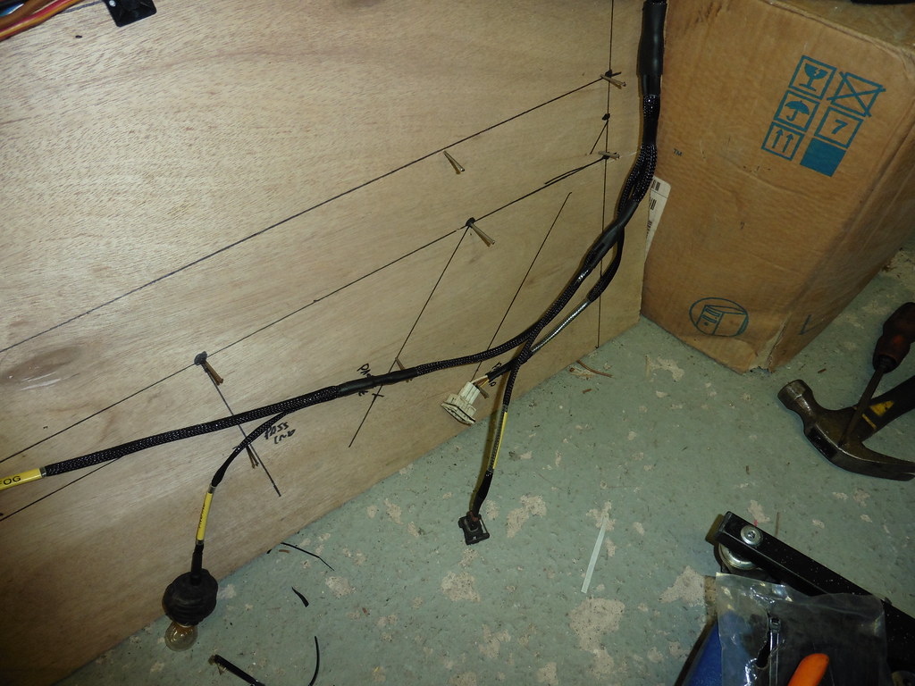 P1030965 P1030965 by jono_misfit, on Flickr I needed to add an earth splice in to feed the lights, which helped on the setup for the braiding.  P1030966 P1030966 by jono_misfit, on Flickr Earths run to the new ear stud location, and there will be a bulkhead stud for the main alternator / starter motor feeds.  P1030967 P1030967 by jono_misfit, on Flickr getting the sequence right on the cross bulkhead run to do it without hainvg to split cables took somethinking on, but got there in the end.  P1030968 P1030968 by jono_misfit, on Flickr last piece to tackle will be the joint for both legs and the run to the bulkhead connector.  P1030969 P1030969 by jono_misfit, on Flickr I think i'll be trial fitting it first to work out how the routing needs to go. I may need to buy a moulded T boot to do it. |
| |
|
|
|
|
|
Jul 19, 2020 19:21:39 GMT
|
|
Looks logical, i just know i would forget something
|
| |
|
|
jonomisfit
Club Retro Rides Member
Posts: 1,787
Club RR Member Number: 49
|
|
Jul 19, 2020 22:04:49 GMT
|
|
I really hope I haven't!
|
| |
|
|
samta22
Club Retro Rides Member
Stuck in once more...
Posts: 1,276  Club RR Member Number: 32
|
|
|
|
Be interested to see how you get on with these, exactly what I was looking to use for connecting the dash sub loom in my project. I've a feeling a rather large order for wiring and associated ancillaries will be going in soon... All coming together nicely - keep up the good work |
| |
'37 Austin 7 '56 Austin A35 '58 Austin A35 '65 Triumph Herald 12/50 '69 MGB GT '74 MGB GT V8'73 TA22 Toyota Celica restoration'95 Mercedes SL320 '04 MGTF 135 'Cool Blue' (Mrs' Baby) '05 Land Rover Discovery 3 V8 '67 Abarth 595 (Mrs' runabout) '18 Disco V |
|
jonomisfit
Club Retro Rides Member
Posts: 1,787
Club RR Member Number: 49
|
|
Jul 25, 2020 19:30:43 GMT
|
I put the loom vaguelly into position to make sure there arent going to be any issue with it. The biggest problem I can see is there is a bit too much length on the headlights, Which is strange as length wise its all the same as the original loom and the branches are all at the same point. I guess it'll be somethign to do with the way I've routed the cables. but if worse comes to the worst I can loose the extra length in a helix if needed. 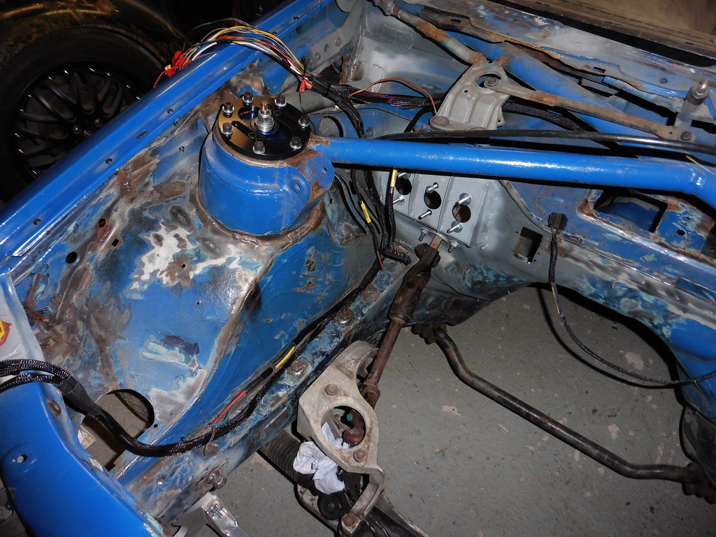 P1030970 P1030970 by jono_misfit, on Flickr the power feed and main earth point lined up nicely to where I wanted them. they'll go onto the two "ribs" near the cage member.  P1030971 P1030971 by jono_misfit, on Flickr I've also couldnt find a side light conection. The headlight has two wires, but i'm assuming thats dipped and main. 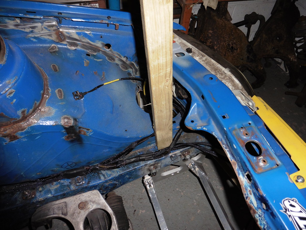 P1030972 P1030972 by jono_misfit, on Flickr I then moved on to having a look at the engine loom as I know here are some connections I need to make to feed the ECU. 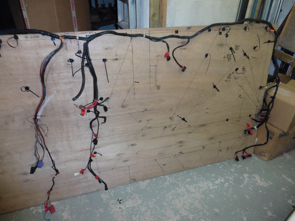 P1030973 P1030973 by jono_misfit, on Flickr I was hoping not to have to strip back the loom binding, but I needed to move some wires...  P1030974 P1030974 by jono_misfit, on Flickr I screwed the key end devices onto the board.  P1030975 P1030975 by jono_misfit, on Flickr then started tracing back the bits I needed. There are some diagnostic ports that arent needed, plus ECU feeds, tacho drive etc I needed to pull back to inside the car.  P1030976 P1030976 by jono_misfit, on Flickr I stripped out the alternator feed from the loom as its already in the car loom. 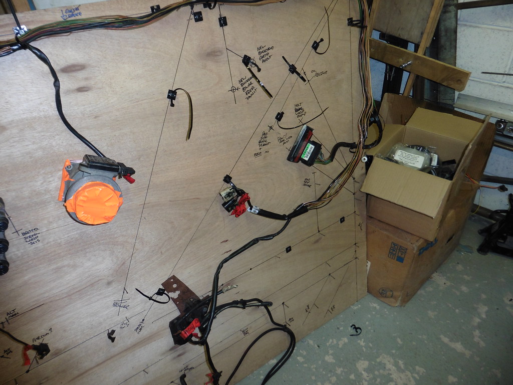 P1030977 P1030977 by jono_misfit, on Flickr I was horrible stripping back the loom tape. On the escort the loom tape was non-sticking so when removed all was fine. On the loom for this engine it was electrical tape and the whole loom has a layer of sticky goo left after I've removed the tape. I tried cleaning with detergent but it doesnt remove it, and I'm a bit loathed to wipe with petrol or thinners. Will see what some air does to it.. I then temporarily taped the loom back together and put it into the car to see things end up in the right places.  P1030978 P1030978 by jono_misfit, on Flickr its going to get quite busy with looms! 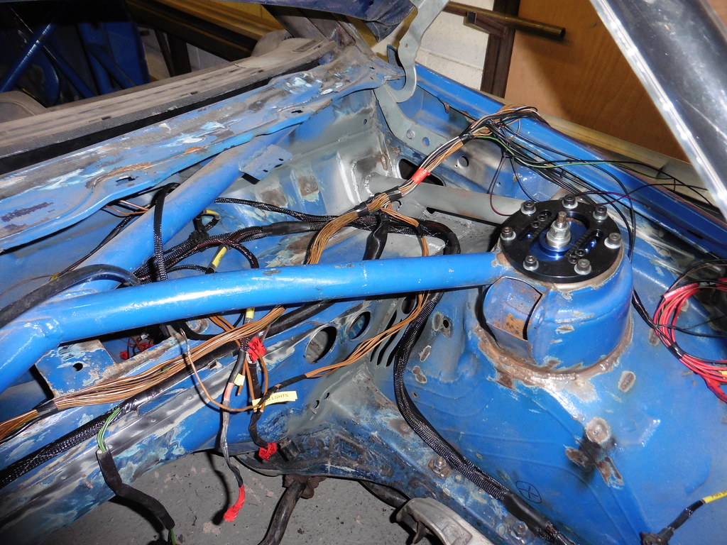 P1030979 P1030979 by jono_misfit, on Flickr All the bits going over the wing will go through the hole in the bulkhead for the ECU and internal connections.  P1030980 P1030980 by jono_misfit, on Flickr having checked it all fitted I then put it back on the board and started putting the loom braid on it. 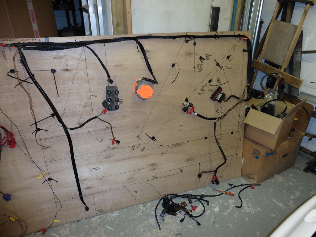 P1030981 P1030981 by jono_misfit, on Flickr Whilst doing this It dawned on me i'd routed the loom the wrong way in the car. I couldnt think why the connector for the MAF sensor was coming out in the middle of the bulkhead, when I know the airbox goes on the wing. It then dawned on me that the loom doesnt run over the bulkhead like the Sierra's / Escorts loom does, but run down the inner wing and across the bar in front of the radiator. Will need to remember that when I run it in. As I really don't want to mess with any of the connectors I'm having to go a size up on the braid in order to get it over the top of a load of the connector. Which is fine, the issue comes with then closing the braid. As i'm using glued heat shrink I experimented with cutting a section of tube open, wrapping the end with the flat piece of heat shrink like a swiss roll, clamping it lightly, then heating it to set. It worked surprisingly well,l and once it had cooled the ends had bonded OK. I'm going to do a search for a non shrinking glued version and If I find one i'll likely use that instead. |
| |
|
|
mk2cossie
Club Retro Rides Member
Posts: 3,058  Club RR Member Number: 77
|
|
Jul 25, 2020 19:40:10 GMT
|
Very nice progress on the looms there  Is it worth rerouting the engine harness along the bulkhead, and losing the lenght of loom for tidiness and weight saving? (In the absence of any swaging goodness) |
| |
|
|
 P1030950 by jono_misfit, on Flickr
 P1030951 by jono_misfit, on Flickr
 P1030950 by jono_misfit, on Flickr
 P1030951 by jono_misfit, on Flickr


