jonomisfit
Club Retro Rides Member
Posts: 1,787
Club RR Member Number: 49
|
|
Jul 25, 2020 20:00:08 GMT
|
I think I may well do that. It also means I don't have wirring sitting next to the hot rad, and ripe for being broken in any nudges it may get. I think i've also found out where the side lights connections are... Escort cosworths have indicators in the front bumper, what look like indicators next to the headlights are the side lights.. as per the below  These go for STUPID money (£150+ each...) so a different solution may be required in the interim. Mot tests says.... "Front and rear position lamps Vehicles must have 2 front and 2 rear position lamps, except for tricycles or quadricycles that are less than 1,300mm wide. Daytime running lamps (DRLs) or headlamps may function as front position lamps. " So I may just wire it up so first stage lights are headlights, not side lights. The side lights can then be blanked off. which appears a common mod when fitting morretti round lights anyway. |
| |
Last Edit: Jul 25, 2020 20:01:13 GMT by jonomisfit
|
|
|
|
mk2cossie
Club Retro Rides Member
Posts: 3,058  Club RR Member Number: 77
|
|
Jul 25, 2020 20:37:40 GMT
|
Only that won't work for position lights, as they need to be a separate low output checked with the ignition off  How much are clear indicators for the normal escorts? Or even use the normal front indicator unit with a 5/21w bulb, side light and indicator in one unit that way |
| |
|
|
jonomisfit
Club Retro Rides Member
Posts: 1,787
Club RR Member Number: 49
|
|
Jul 25, 2020 20:55:28 GMT
|
|
Its custom wired. The ignition switch is for the ignition only.
The isolator switch does everything else. If it proves to be an issue I can always mount some LED's in the headlight somewhere.
If you look a the picture above you can see the headlights extend into the wing. For normal escorts the headlights end at the wing join line. This makes the normal indicators much wider than the escort/xr3i/rs2000 side lights, as such they don't fit in the space thats left.
I have a pair and if worst comes to the worst I can cut them down to make them all fit. I just suspect it will not look the best.
Or, failing that, I'll fit the set of morretti double round headlights I have, which have the side lights built into them.
|
| |
|
|
jonomisfit
Club Retro Rides Member
Posts: 1,787
Club RR Member Number: 49
|
|
Jul 31, 2020 19:35:53 GMT
|
It was hot which was removing a lot of my enthusiasm today. i finished braiding the exterior engine loom  P1030983 P1030983 by jono_misfit, on Flickr the routed it round the engine bay again to check it'll work OK.  P1030984 P1030984 by jono_misfit, on Flickr  P1030985 P1030985 by jono_misfit, on Flickr 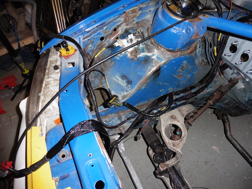 P1030986 P1030986 by jono_misfit, on Flickr Should all work out ok. I need to buy a few bits and make a couple of things before I can finish it up though. So stripped the last bit of loom out, the on engine loom that has key sensors and fuel injector connections.  P1030987 P1030987 by jono_misfit, on Flickr It is knackered. If for no reason than cables are baked, the insulation is going hard, and all the cable protection sleaving has gone brittle and is flaking off. And then you get to my favourite bits.... the previous repairs to idle speed control valve wiring.  P1030988 P1030988 by jono_misfit, on Flickr At least they used connector block and insulating ta..... hold on..... thats green masking tape.... Looking at it some of the insulation looked freyed on the earth wire. I'll just follow that back..  P1030989 P1030989 by jono_misfit, on Flickr Uh huh..... theres no insulation left on that bit... protected by the sleave only. I'll just follow it back...  P1030990 P1030990 by jono_misfit, on Flickr Uh huh.... there's no insulation on the wire still and there's a molten mass of plastic where it used to be...  P1030991 P1030991 by jono_misfit, on Flickr Uh huh... it just keeps going...  P1030992 P1030992 by jono_misfit, on Flickr none of that looks healthy. I'm very very surprised this engine was still running before we took it out of the car. Thats had a very decent short, with a decent sized load on it for a decent length of time. The loom is well and trully knackered on the injector leg! Definitely need to make a new loom piece. So pegged out the existing loom like some extra from an alien autopsy.  P1030993 P1030993 by jono_misfit, on Flickr I need to buy some more junior power time connectors for the Injectors, and a couple of 8 way water proof connectors for the jump back the the other loom. |
| |
|
|
Darkspeed
Club Retro Rides Member
Posts: 4,873
Club RR Member Number: 39
|
|
Jul 31, 2020 20:55:22 GMT
|
Anyone who as owned an old Ford will be more than familiar with a view like that. - And the smell......  |
| |
|
|
jonomisfit
Club Retro Rides Member
Posts: 1,787
Club RR Member Number: 49
|
|
Jul 31, 2020 21:38:18 GMT
|
|
like a cat thats been on the BBQ too long....
|
| |
|
|
melle
South West
It'll come out in the wash.
Posts: 2,010
|
|
Jul 31, 2020 21:55:22 GMT
|
I need to buy some more junior power time connectors for the Injectors I recently bought a couple Rover 400 injector looms on eBay for a fiver apiece posted. I searched for "injector loom", selected cheapest first and then kept scrolling until the first loom with JPT connectors popped up. |
| |
www.saabv4.com'70 Saab 96 V4 "The Devil's Own V4" '77 Saab 95 V4 van conversion project '88 Saab 900i 8V
|
|
jonomisfit
Club Retro Rides Member
Posts: 1,787
Club RR Member Number: 49
|
|
|
|
|
I just bought a couple of packs of 4 from an electrical supplier.
I think it was £7 for 4 including all terminals, seals, and boots.
My only concern with re-use of looms is around if the heat cycles on the engine have degraded the insulation. Admittedly most don't route the wiring in the oven that is the v6 valley
I have had to buy a crimp tool though as the one I have isn't right for JPT pins.
But I needed that no matter which way I went.
|
| |
|
|
melle
South West
It'll come out in the wash.
Posts: 2,010
|
|
|
|
I once bought knock-off JPT plugs and they were rubbish (the plastic disintegrated in no time), so genuine used ones it is for me now. New genuine ones aren't ridiculously expensive either, but I like repurposing stuff if possible. I buy boots from 3 Way Components on eBay (they used to have packs of 10, but I don't see those any more). |
| |
www.saabv4.com'70 Saab 96 V4 "The Devil's Own V4" '77 Saab 95 V4 van conversion project '88 Saab 900i 8V
|
|
jonomisfit
Club Retro Rides Member
Posts: 1,787
Club RR Member Number: 49
|
|
|
|
|
I'll give these a good look over when they arrive and see what I think of the quality.
There were other JPTs on eBay that looked a lot cheaper made so figured they were definitely stay away ones.
|
| |
|
|
melle
South West
It'll come out in the wash.
Posts: 2,010
|
|
|
|
|
I have to admit the ones I bought were the cheapest I could find from a UK seller on eBay, can't remember who it was.
|
| |
www.saabv4.com'70 Saab 96 V4 "The Devil's Own V4" '77 Saab 95 V4 van conversion project '88 Saab 900i 8V
|
|
jonomisfit
Club Retro Rides Member
Posts: 1,787
Club RR Member Number: 49
|
|
|
|
started unbinding the engien loom and checking for further damage 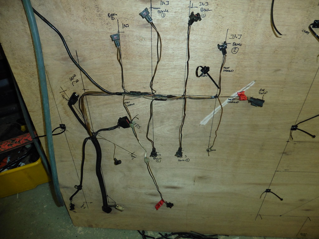 P1030999 P1030999 by jono_misfit, on Flickr the rest of it was fairly OK, although there were a few wires with nicks in them.  P1040009 P1040009 by jono_misfit, on Flickr Just waiting for the bits now. I measured up a few things and made a list of more bits I need to get. The thought i better finish off the last bits of cable routings. marked out some steel  P1030994 P1030994 by jono_misfit, on Flickr trimmed and folded to make this  P1030995 P1030995 by jono_misfit, on Flickr and another one  P1030996 P1030996 by jono_misfit, on Flickr then welded them in  P1040001 P1040001 by jono_misfit, on Flickr  P1040002 P1040002 by jono_misfit, on Flickr these are stiffeners for where the cables will go through the panels. Most likely overkill, but I want somewhere for the grommet to hold onto properly. then made their bigger brother up, which is the transit strengthener for where the fuel connections will go  P1030998 P1030998 by jono_misfit, on Flickr  P1040003 P1040003 by jono_misfit, on Flickr it was really not easy to get into and I couldnt see what I was welding. Lesson learned and I should have fitted this before I welded in the box side. then started on the fuel line routing Drilled some holes in the seat mount / floor brace  P1040005 P1040005 by jono_misfit, on Flickr  P1040006 P1040006 by jono_misfit, on Flickr then opened them into a slot with the die grinder, again... note to self do this before fitting seat rails in the future... 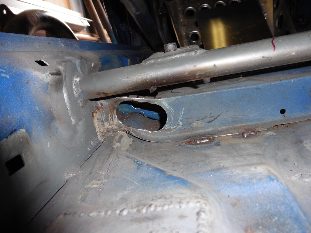 P1040007 P1040007 by jono_misfit, on Flickr  P1040008 P1040008 by jono_misfit, on Flickr I've still got to make a flange / strengthener for them. Looking on the pics of a number of group A escort / wrc cars I can find, they just cut the last 100mm of the seat rail out to let the hoses pass through. I think retaining be a bit better. I then did some tidying up and thinking about bits I need to do to get to paint. |
| |
|
|
jonomisfit
Club Retro Rides Member
Posts: 1,787
Club RR Member Number: 49
|
|
|
|
some bits arrived.  P1040011 P1040011 by jono_misfit, on Flickr so i thought i'd make use of this bit  P1040012 P1040012 by jono_misfit, on Flickr I need to make a split collar bulkhead transit for the ECU loom as I'm not taking the ECU connector off the loom. Some CAD modelling. Something like so, although probably with a couple of hold down tabs rather than the overly complicated and difficult to machine (for me) collar arrangement. 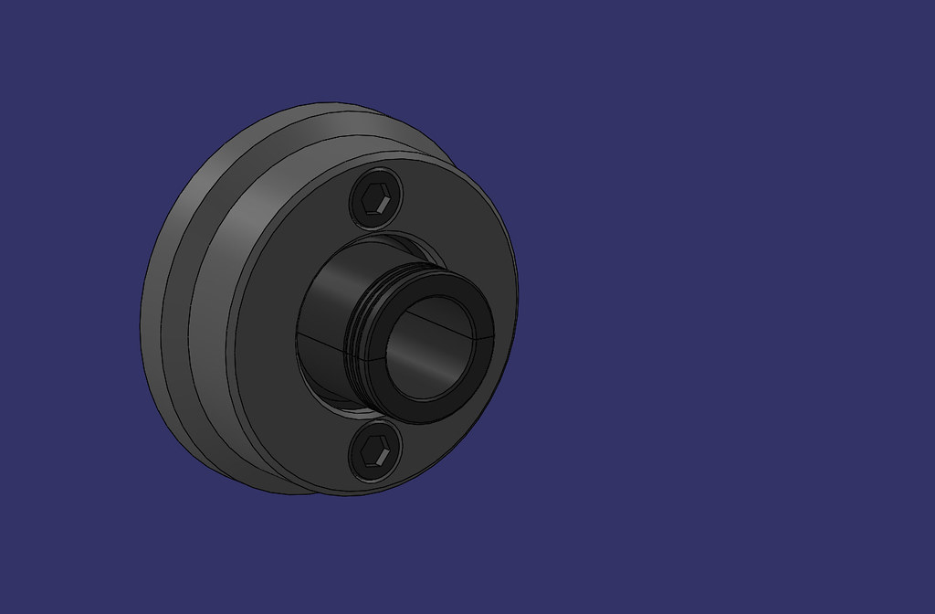 Bulkhead Penetrator assy Bulkhead Penetrator assy by jono_misfit, on Flickr  Bulkhead Penetrator assy -2 Bulkhead Penetrator assy -2 by jono_misfit, on Flickr  Bulkhead Penetrator assy-3 Bulkhead Penetrator assy-3 by jono_misfit, on Flickr  Bulkhead Penetrator assy-4 Bulkhead Penetrator assy-4 by jono_misfit, on Flickr so have to make two of these.  Bulkhead Pen - Piece 2 Bulkhead Pen - Piece 2 by jono_misfit, on Flickr It looks huge, as everythign does in CAD, but for scale its 65mm diam and 50mm long. Cut a lump off the nylon off. Chucked it up and started taking some cuts.  P1040013 P1040013 by jono_misfit, on Flickr took some more cuts to get it vaguelly the right dimensions  P1040014 P1040014 by jono_misfit, on Flickr I forgot how much I don't like cutting nylon. then very carefully cut it in half.  P1040015 P1040015 by jono_misfit, on Flickr but not carefulyl enought as there is a wobble in the middle.  P1040016 P1040016 by jono_misfit, on Flickr flattened the faces off in the mill  P1040017 P1040017 by jono_misfit, on Flickr drilled and tapped, then bolted together  P1040018 P1040018 by jono_misfit, on Flickr Trued it up and started getting it to final dimensions.  P1040019 P1040019 by jono_misfit, on Flickr Will finish it tomorrow hopefully. |
| |
|
|
jonomisfit
Club Retro Rides Member
Posts: 1,787
Club RR Member Number: 49
|
|
|
|
I finished turning the profile, but its not as neet as i'd like. 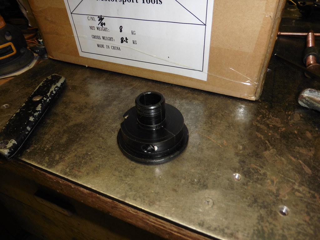 P1040020 P1040020 by jono_misfit, on Flickr I messed up on the dimensions slightly so the cap head set screws and just sitting proud, or would be it I hadnt nudged the corner off. And I got the latereal distance wrong on one as its broken through as well. 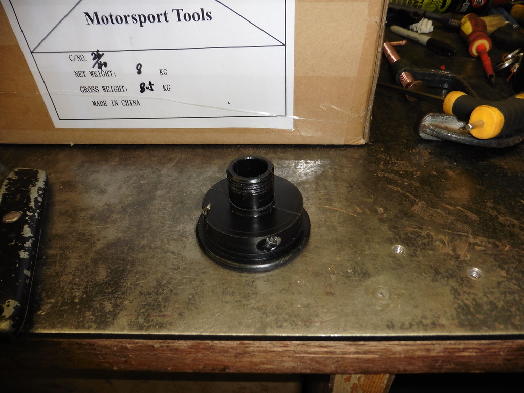 P1040021 P1040021 by jono_misfit, on Flickr And in two halves.  P1040022 P1040022 by jono_misfit, on Flickr fits like so 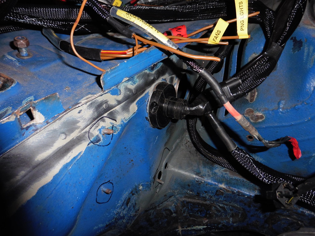 P1040023 P1040023 by jono_misfit, on Flickr  P1040024 P1040024 by jono_misfit, on Flickr once bolted up it'll be bound to the loom. I still need to make a couple of mounting tabs for it when I come to fit it. maked up for bulkhead power transits  P1040025 P1040025 by jono_misfit, on Flickr drilled and bolted in  P1040026 P1040026 by jono_misfit, on Flickr I'm going to turn up a litte collar / terminal mount for the ground conection, which will be welded onto the bulkhead took the dash back out and removed the Airbag module  P1040027 P1040027 by jono_misfit, on Flickr which gives a good mount for a trip meter or something else.  P1040028 P1040028 by jono_misfit, on Flickr There's just not enough space in the centre panel I made up fitting inside the existing cut out. Looking on line at Grp A cars the just cut out the whole lower dash and re-make. I'm going to start with a bit of a trim and see how I get on.  P1040029 P1040029 by jono_misfit, on Flickr  P1040030 P1040030 by jono_misfit, on Flickr there is now a lot more space, hopefully its enough! 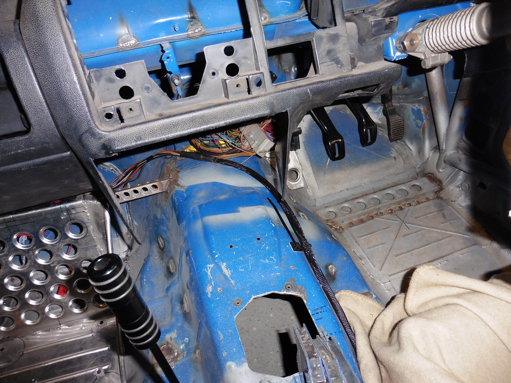 P1040031 P1040031 by jono_misfit, on Flickr Dashboard pad back in  P1040032 P1040032 by jono_misfit, on Flickr then started on the engine wiring loom as some bits turned up in the post. main loom connectors are going to be removed and replaced with a differnt type as I have looked but cant find the terminals for this.  P1040033 P1040033 by jono_misfit, on Flickr  P1040034 P1040034 by jono_misfit, on Flickr There's a red cover inside that gets pulled out, then you lift a tang and slide out each terminal. note the fretting on the black wire (which is either main switched live, or main ground)  P1040035 P1040035 by jono_misfit, on Flickr  P1040037 P1040037 by jono_misfit, on Flickr  P1040038 P1040038 by jono_misfit, on Flickr Crumbly / burnt old injector cabling removed and started running in the new wires.  P1040039 P1040039 by jono_misfit, on Flickr The Junior Power Timer connectors I orded up arrived and they seem pretty decent quality. The feel as robust as the ford ones, and fit nicely. They have a decent thickness of clip wire as well. Hopefulyl they are good. |
| |
|
|
jonomisfit
Club Retro Rides Member
Posts: 1,787
Club RR Member Number: 49
|
|
|
|
|
|
| |
|
|
jonomisfit
Club Retro Rides Member
Posts: 1,787
Club RR Member Number: 49
|
|
Aug 14, 2020 20:19:53 GMT
|
|
|
| |
|
|
jonomisfit
Club Retro Rides Member
Posts: 1,787
Club RR Member Number: 49
|
|
Aug 14, 2020 20:32:54 GMT
|
I continued on with the engine harness. Started splicing the Injector feeds (as bank fired) using an open crimp  P1040040 P1040040 by jono_misfit, on Flickr  P1040041 P1040041 by jono_misfit, on Flickr (macro mode has gone bonkers with the flash for some reason) and started laying out the loom 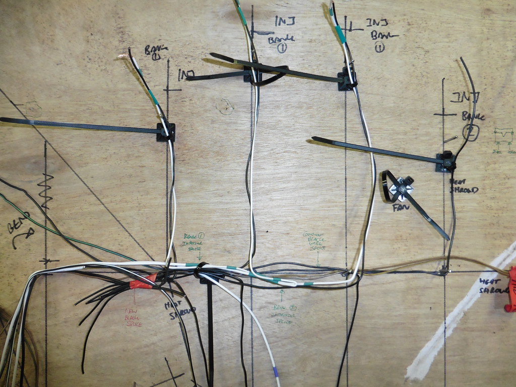 P1040042 P1040042 by jono_misfit, on Flickr laying out bank two feeds (green bands bank 1, purple bands bank 2)  P1040043 P1040043 by jono_misfit, on Flickr open crimp in the tool  P1040044 P1040044 by jono_misfit, on Flickr cables carefully fed in and crimp about to be made  P1040045 P1040045 by jono_misfit, on Flickr solid crimp tested with a good tug  P1040047 P1040047 by jono_misfit, on Flickr two layers of heat shrink added  P1040048 P1040048 by jono_misfit, on Flickr then routed on the board 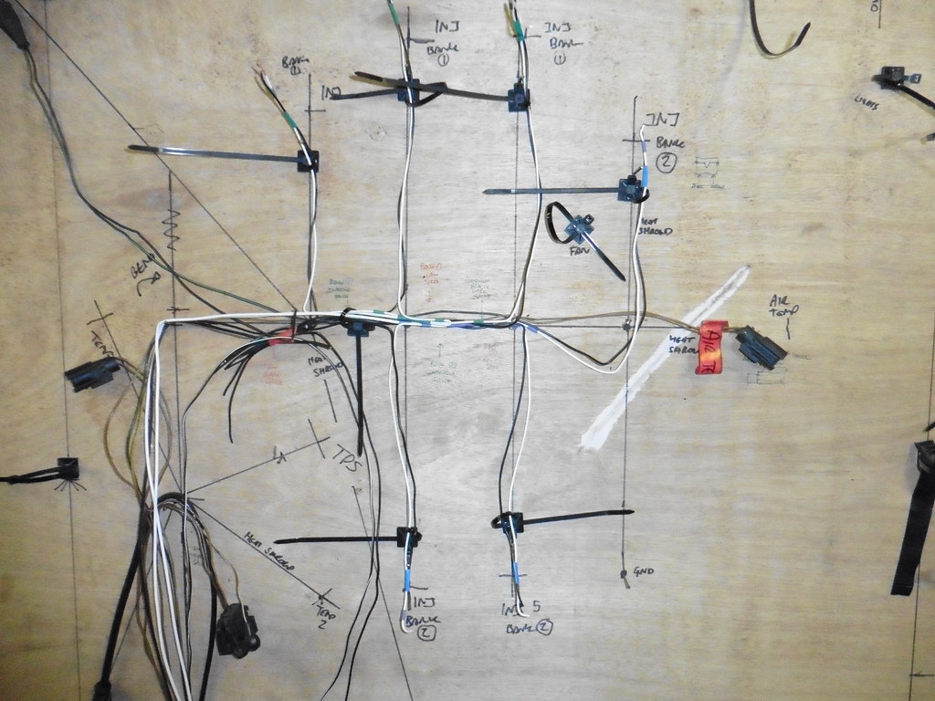 P1040049 P1040049 by jono_misfit, on Flickr I don't have a big enought crimp to make all the black connections in one go, so ive staged the crimps on the main feed. I stripped back 10mm of insulation mid wire, crimped on three wires, then stripped insulation at the end of the wire and crimped onthe remainder.  P1040050 P1040050 by jono_misfit, on Flickr its not so easy to see in the bad pic back on the pin board  P1040051 P1040051 by jono_misfit, on Flickr then started applying the high temp braid and idents  P1040052 P1040052 by jono_misfit, on Flickr more sheathing progress 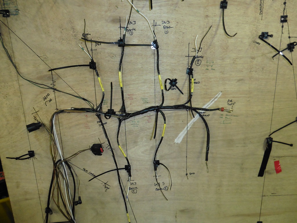 P1040053 P1040053 by jono_misfit, on Flickr then ran out of time for today. |
| |
|
|
mk2cossie
Club Retro Rides Member
Posts: 3,058  Club RR Member Number: 77
|
|
Aug 14, 2020 21:00:41 GMT
|
Although I'm not certain, I have a suspicion that Ford wired cylinders 1, 3, and 5 as one bank, and 2, 4, and 6 as the other  I can dig out the wiring diagrams I may have to check if you like? Liking the look of the centre console tho  Have you thought of using a solid state isolation switch? More expensive than the console mounted one, but easier to fit in remote places without a cable to route |
| |
|
|
jonomisfit
Club Retro Rides Member
Posts: 1,787
Club RR Member Number: 49
|
|
Aug 14, 2020 21:28:05 GMT
|
|
If you've got a wirring diagram that would be great thanks.
You like my unique layout on the board :-) I mean, technically i know i could have put the earth up and the injector down... but i'd already written gnd so it had to stay like that.
My big problem is I don't know which bank was the brown wire and which was the brown with a black tracer..
Thanks
I considered one of them, but to get above a 4 channel 1 is £££. Which i don't have :-( so its fuses and relays for the moment. I was going to get miniature circuit breakers / resetable fuses but pricing them up it soon adds up.
If the funds ever rebound from buying the fuel hose fittings then I might get a solid state switch and do a centre console mk2.
|
| |
Last Edit: Aug 14, 2020 21:29:26 GMT by jonomisfit
|
|
eurogranada
Europe
To tinker or not to tinker, that is the question...
Posts: 2,556
|
|
Aug 15, 2020 14:56:10 GMT
|
|
I think I'm going to steal your idea on that nylon cable thing. I could use one myself.
|
| |
|
|


