|
|
|
Apr 12, 2021 20:15:38 GMT
|
|
|
| |
Last Edit: Apr 12, 2021 20:23:05 GMT by krissto: Numerous typos!
|
|
|
|
|
|
|
Apr 12, 2021 21:13:26 GMT
|
|
Hi
Been following this as i am doing a similar project 77 1500 with a 4age, i presume you are cutting a few inches into the bulkhead to clear the air intake box?
Thanks
|
| |
|
|
|
|
|
|
|
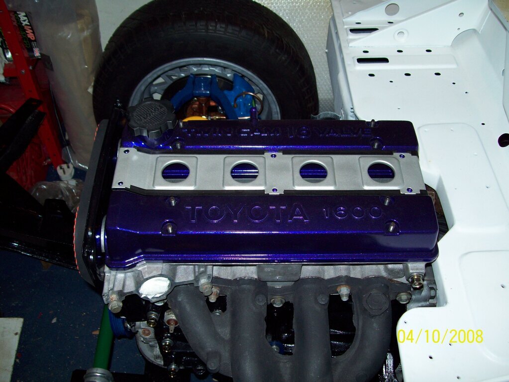
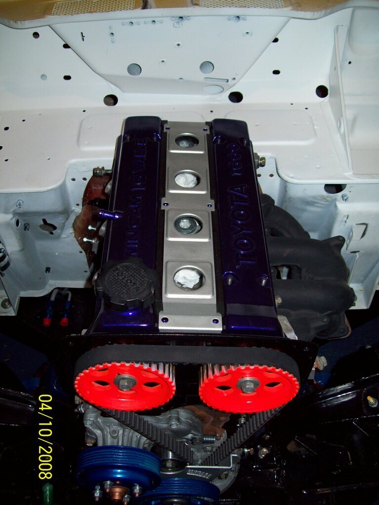
Hi Been following this as i am doing a similar project 77 1500 with a 4age, i presume you are cutting a few inches into the bulkhead to clear the air intake box? Thanks Actually, no. The AE86 (RWD) inlet manifold is clear of the bulkhead, so needs no cutting. The only modification to the firewall is the 'cranked' section to clear the sensors at the rear of the cylinder head, which can be seen in my pictures. |
| |
|
|
|
|
|
Apr 13, 2021 20:27:34 GMT
|
With the engine back in the car, 2008 saw the development of the fuel system, electrical and cooling. First was the fuel tank. I sent a new Spitfire 1500 tank to a specialist who made me a new alloy item with integral swirl pot. Safety foam filled, with VDO DIP tube sender, recess to allow diff access, roll over vent valve, JIC unions etc... 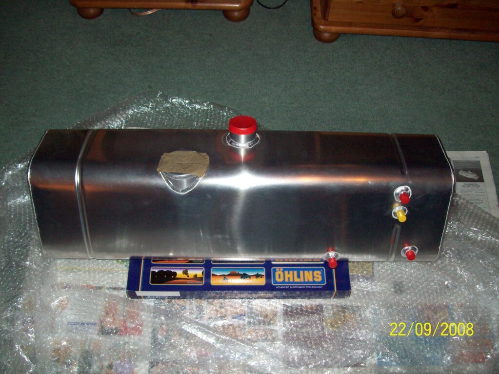 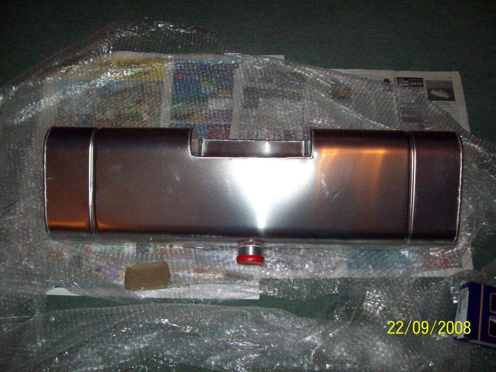 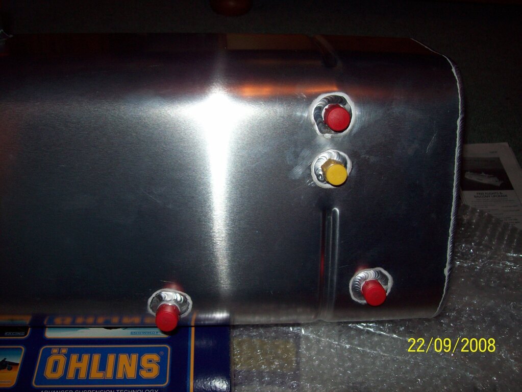 As any Spitfire owner will know, the tank sits between the rear wheel arches and has a flange all around its centre so as to bolt it in place. Sadly, the maker of my new alloy tank decided to delete this option, so I ended up with having to make all sorts of brackets and stainless straps to hold it in place. Undeterred, I carrid on and got a compromise installation sorted... 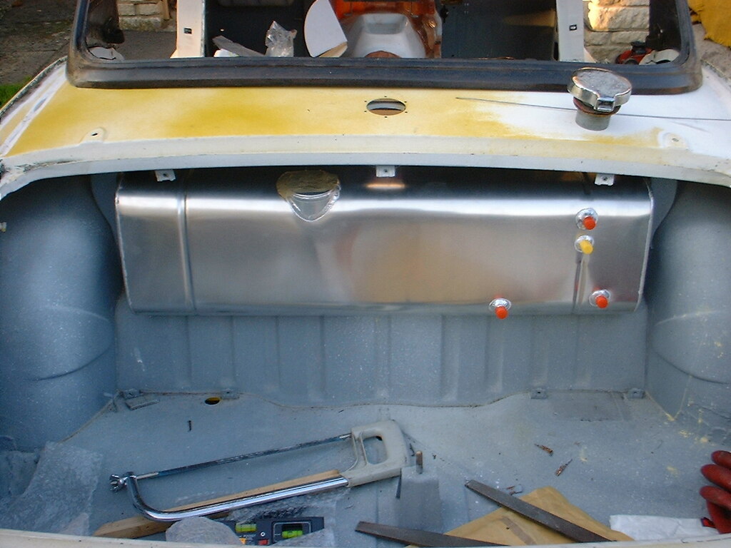 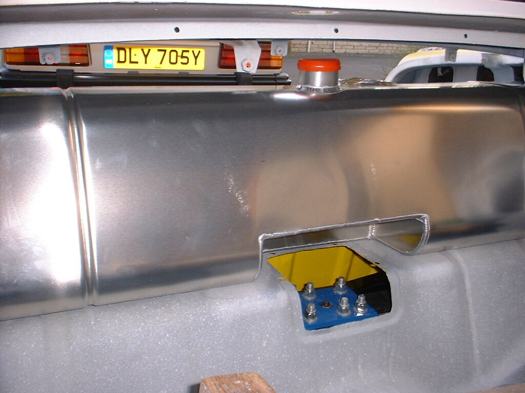 It ended up being a hideous mess of chopped up B&Q brackets and rushed welding... 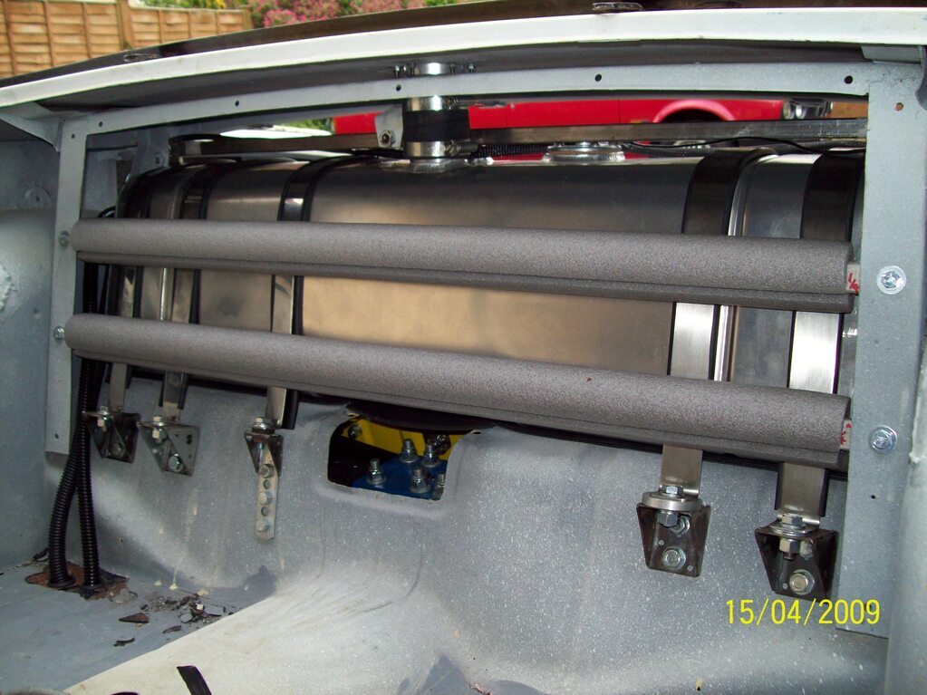 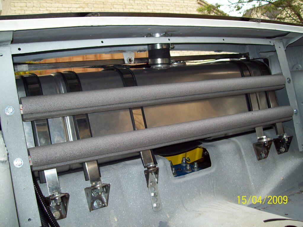 ...and a complicated set of plumbing to provide a lifter pump to feed the collector/swirl pot and Wallbro pump for the injection supply. 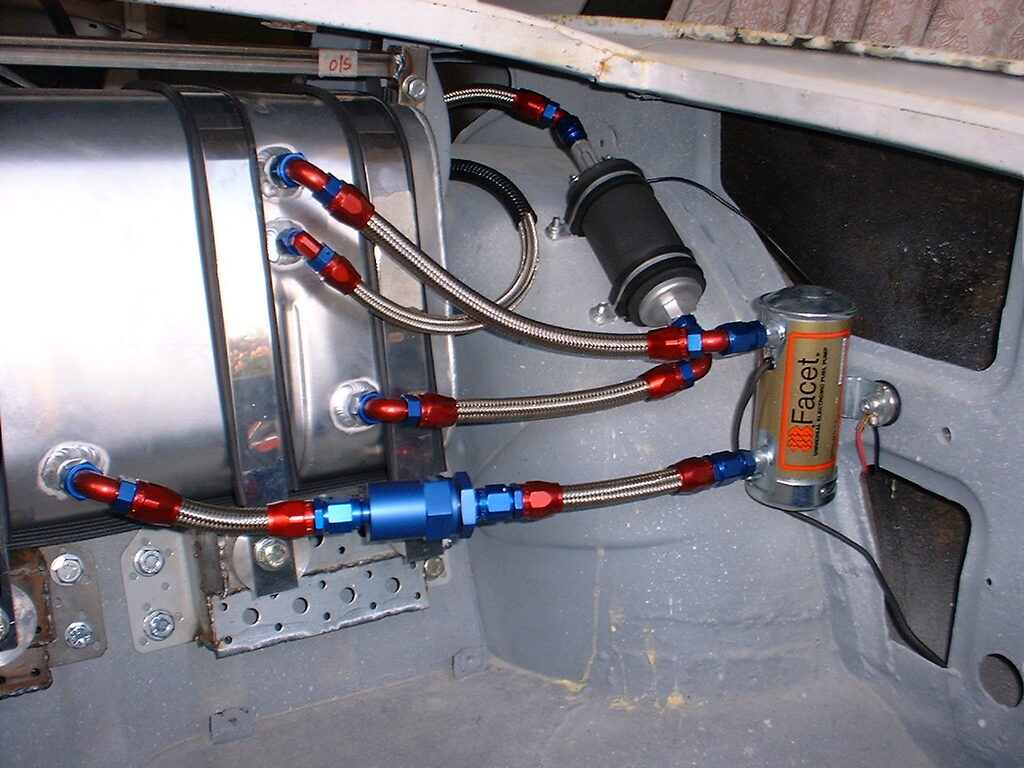 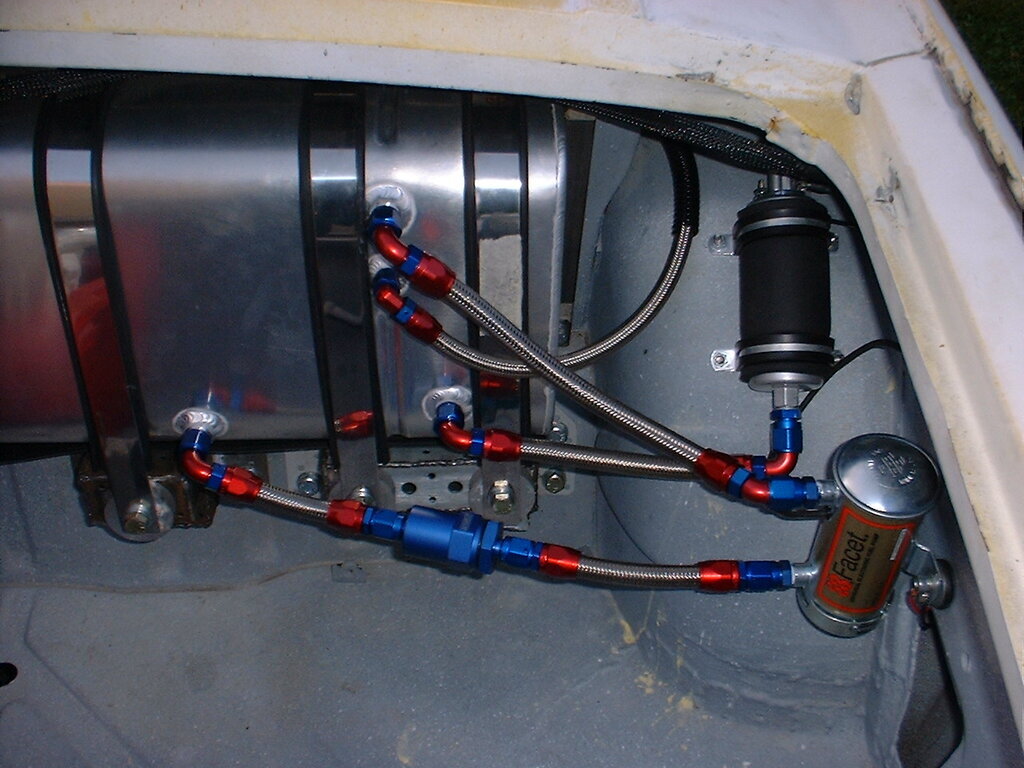 At this point I decided that at least I could get the engine running and prove the various electrical/cooling/fuel systems out. Needless to say that this tank installation has been replace by a bespoke Pro-Alloy tank and much simplified system. More of that in posts to follow. Thanks, Chris |
| |
|
|
|
|
|
Apr 23, 2021 19:20:32 GMT
|
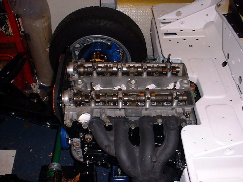
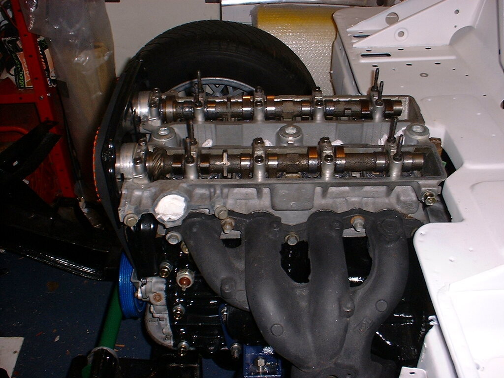
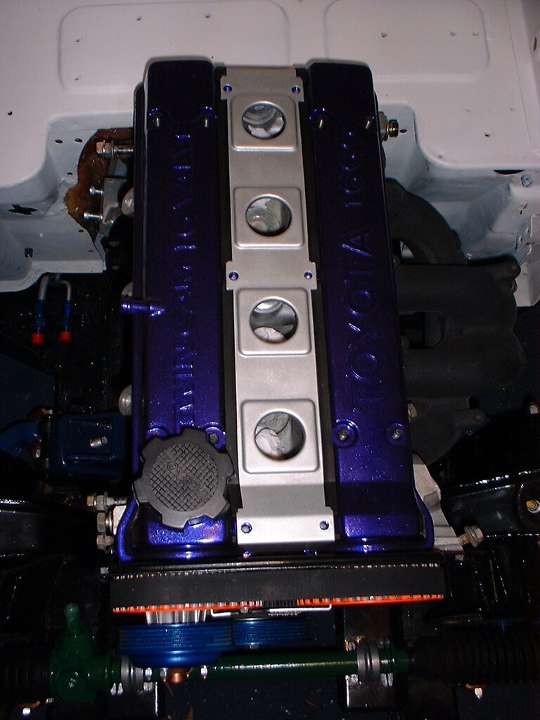
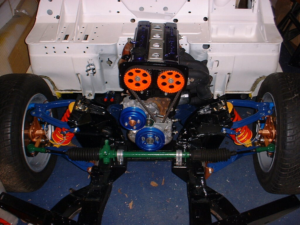
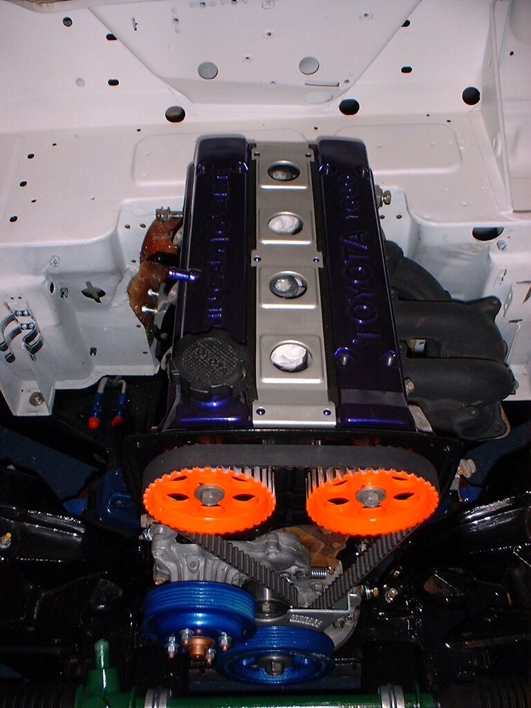
It has been while since my last post. Now we go into late Spring/Summer of 2009 and the engine bay is filling up with stuff. Please bear in mind that this is by no means the final product and much has changed since. The intention, as stated in the previous posts, was to prove the electrical mods, fuel system etc., and get it running. Note that the steel wheels have been replaced at that time with 14" AllyCat Rallye Special. Points to note (all superseded now): - Using the cast iron exhaust manifold and my own mild steel downpipes. - Braking system only single circuit. - Pipercross filter not suitable for the car when bonnet down! - Large 60A alternator high up on N/S. - Radiator is full width but not the correct core. I could go on and on, but I want to get these images out of the way and move onto more interesting engineering since that time. However, the setup you see was fired up and running in 2009 and all systems checked out okay. The only snag encountered was the fact that the injectors were clogged/seized and were sent off for ASNU cleaning. After that, the engine purred... Picures: 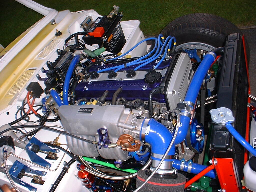 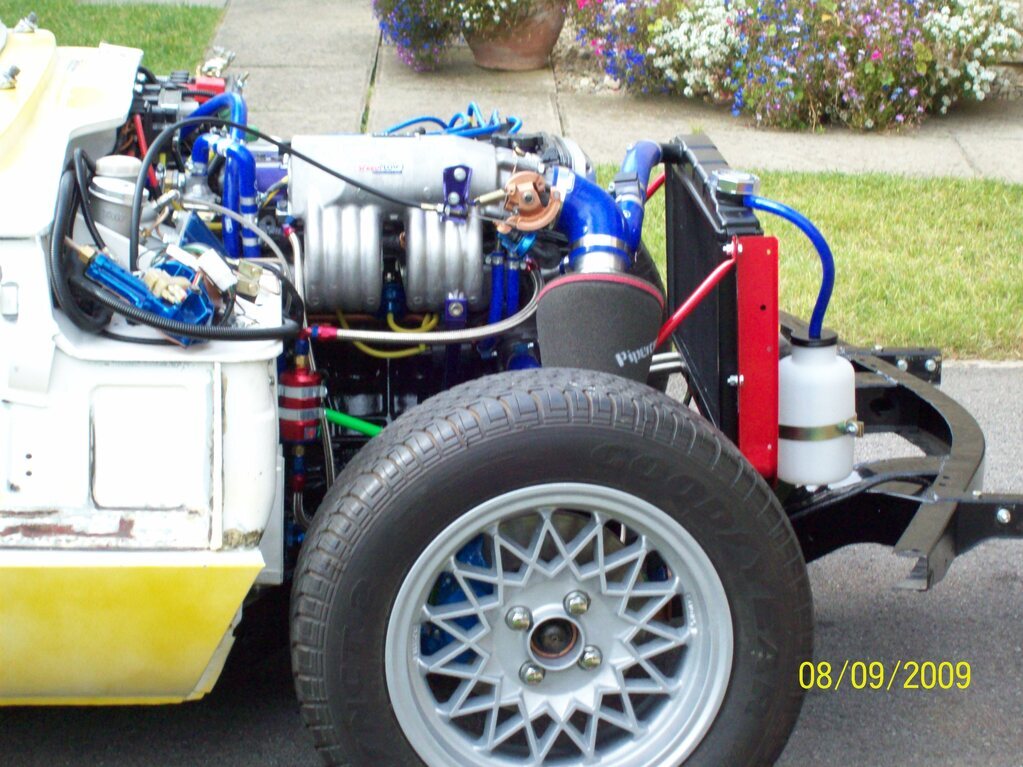 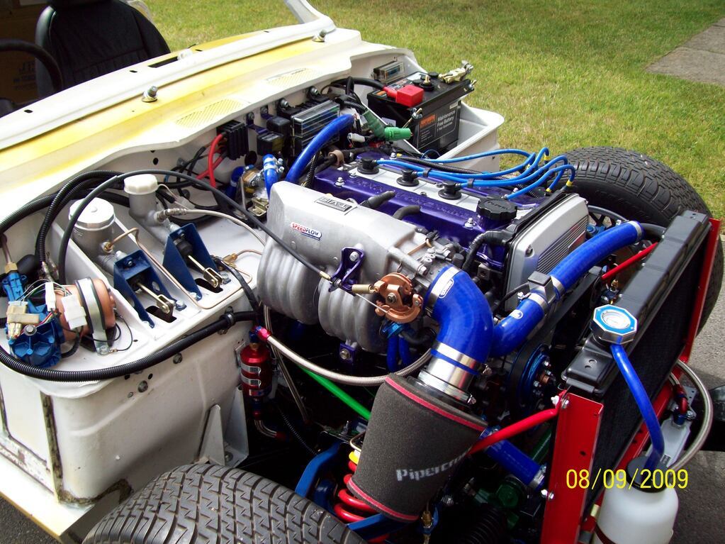 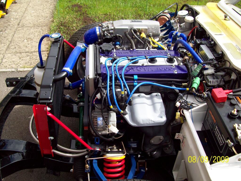 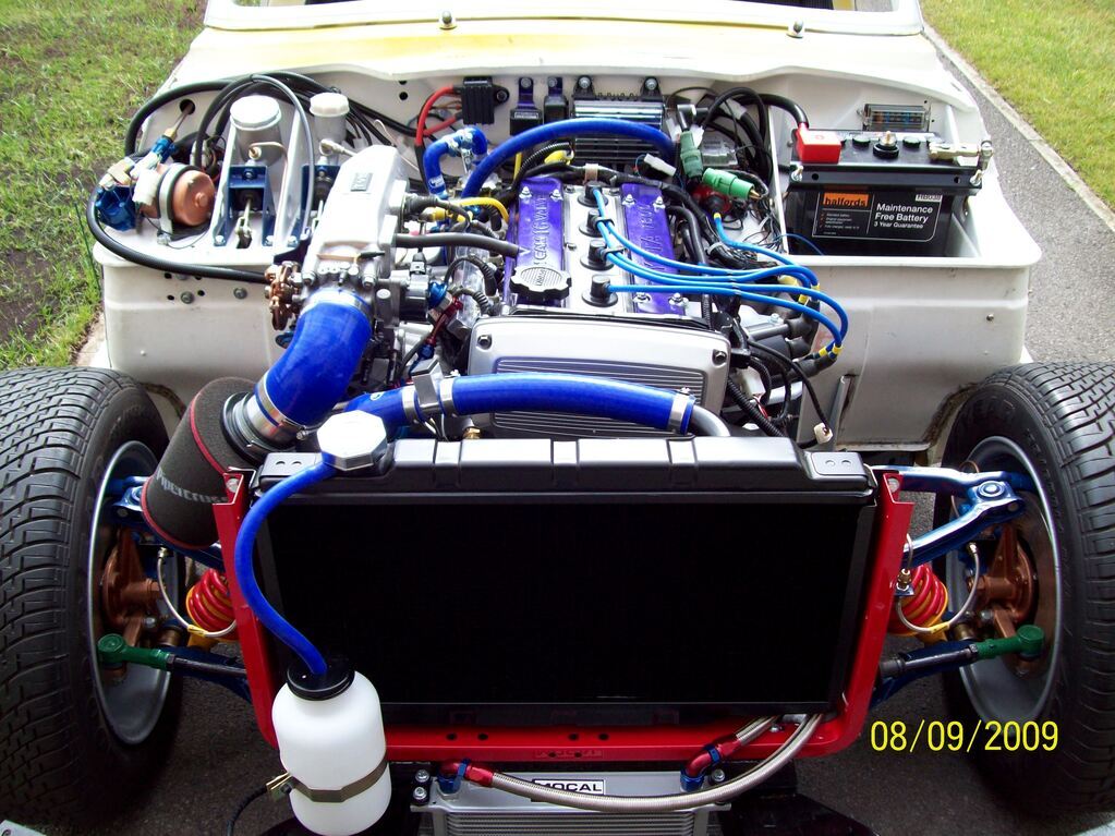 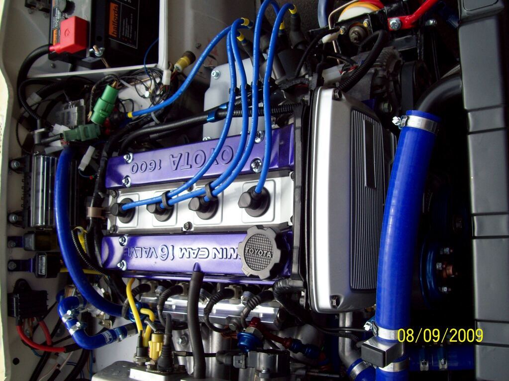 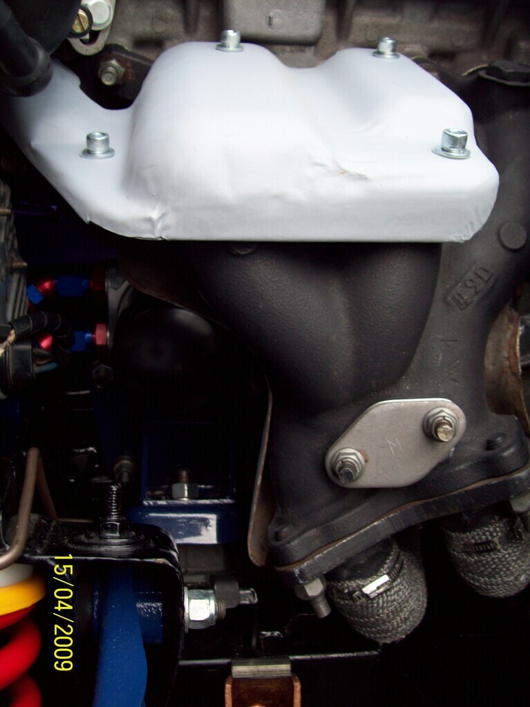 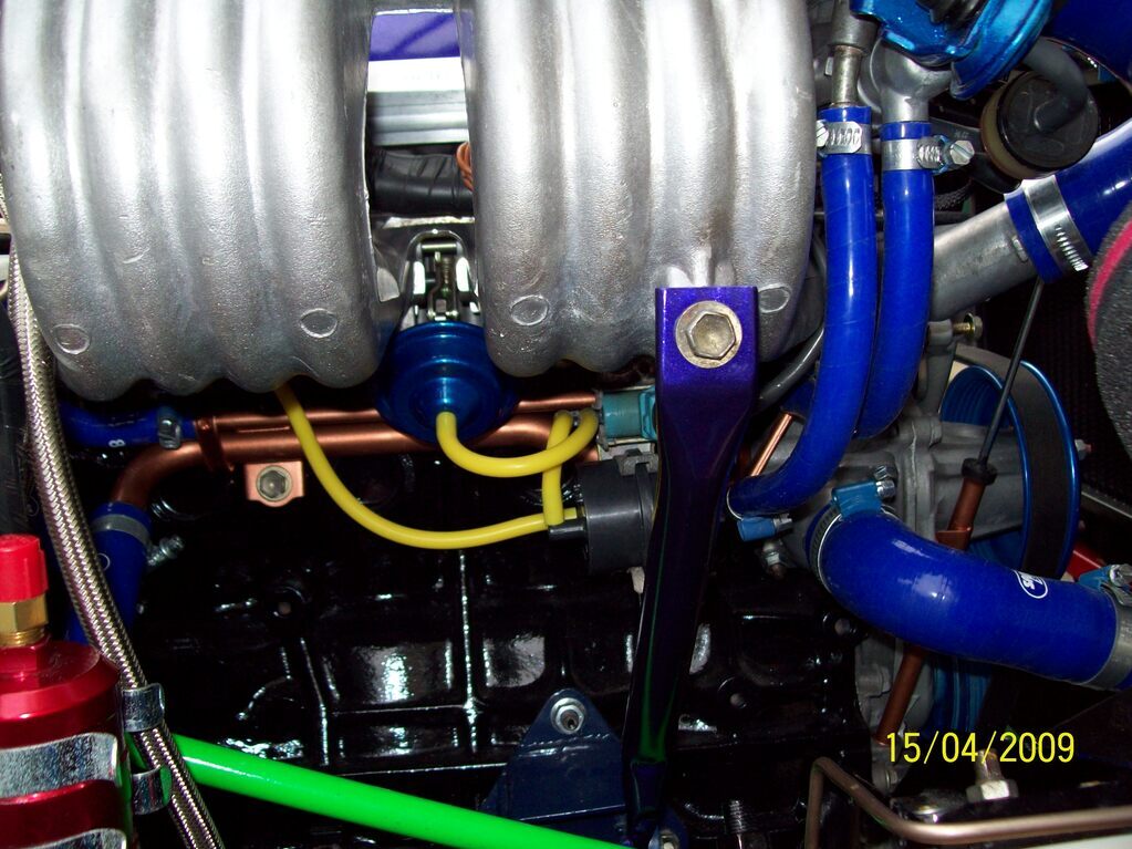 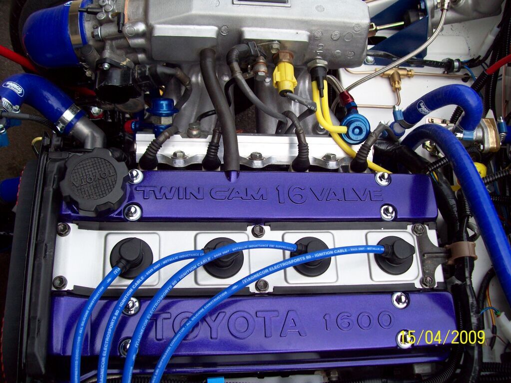 Oh, and the huge battery only used for getting it started... Thanks for watching, Chris |
| |
|
|
|
|
|
May 21, 2021 19:35:10 GMT
|
Gosh, has it really been nearly a month since my last post? Tut-tut to me... So we now move onto what became a busy 2010, with all sorts of revised ideas on the path to achieving what I want out of this car. With the engine assessed as being functional and my other systems okay, time to pull it all apart! Body tub off and some pics of the custom propshaft and the mods to the T50 transmission so that the clutch arm was further up and not interfering with the chassis: 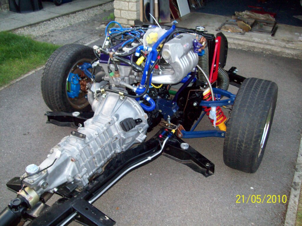 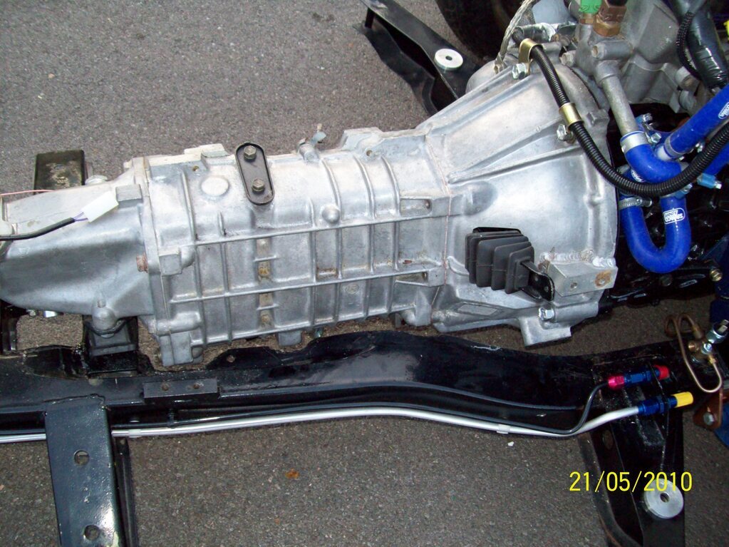 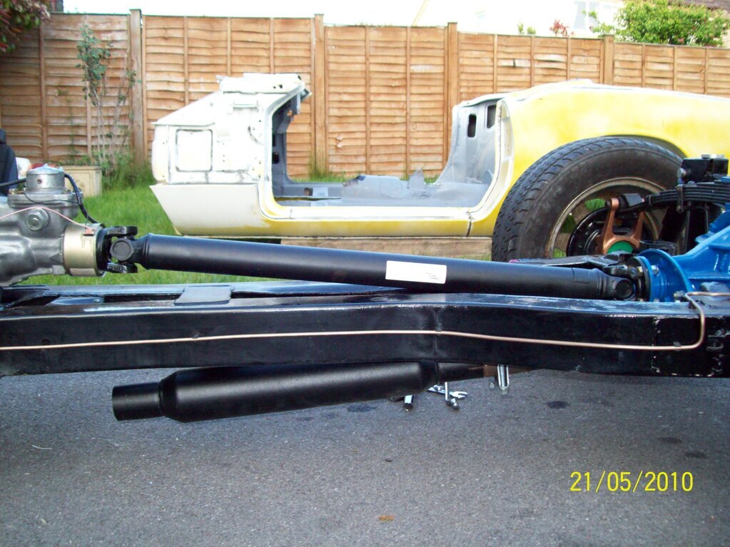 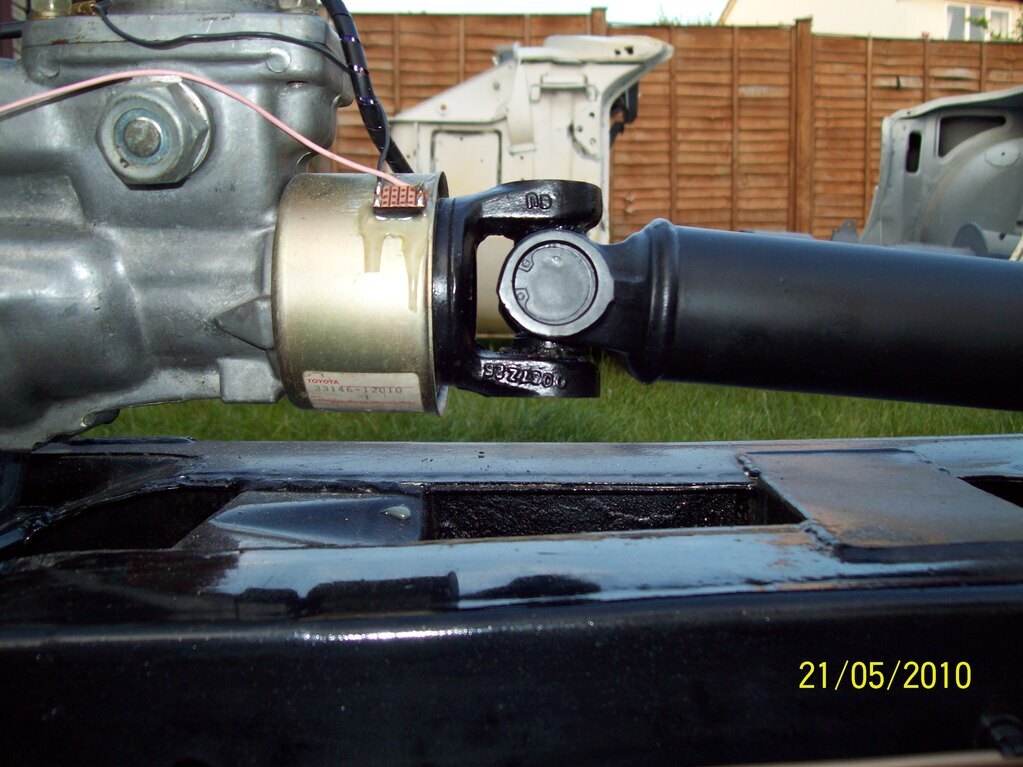 Some might look at this critically and question the U/J angles. It's around 6.5 degrees declination at the gearbox, but is equalised at the diff. Also, the output from the gearbox is on a sliding spline. I believe that all this will cancel out and not cause excessive vibration? In any case, I am not building this car for daily use nor long motorway cruising. The external clutch slave/arm has...guess what?... been superseded. Posted here just to keep the timeline going. Oh, and the experiments with magnets and reed switches on the rear of the T50 did not work out, so a Brantz conversion on the T50 speedo drive is now in place. More of that when we get onto later uploads. Next update might be fairly soon - given this shocking weather of late - meaning stuck indoors... Chris |
| |
|
|
|
|
|
May 22, 2021 20:05:03 GMT
|
|
Ah. Spitfire. I'm loving the 80's vibe with dayglo paint etc and your proper journey with this. I have very little experience of Spits... except for one summer in about 87 or 88 when a friends brother was "looking after" a Spit while his friend was abroad. Cue the inevitable stuffing into an immovable object. This was about 2 weeks before the car was due to be returned having had some love and coddling over the summer... frantic chassis swap and bonnet replacement - that took us all a few evenings. Not sure whether he ever owned up to that one. Happy days.
|
| |
1968 Mini MkII, 1968 VW T1, 1967 VW T1, 1974 VW T1, 1974 VW T1 1303, 1975 Mini 1000 auto, 1979 Chevette, 1981 Cortina, 1978 Mini 1000 1981 Mini City, 1981 Mini van, 1974 Mini Clubman, 1982 Metro City, 1987 Escort, 1989 Lancia Y10, 1989 Cavalier, 1990 Sierra, 1990 Renault 19, 1993 Nova, 1990 Citroen BX, 1994 Ford Scorpio, 1990 Renault Clio, 2004 Citroen C3, 2006 Citroen C2, 2004 Citroen C4, 2013 Citroen DS5. 2017 DS3 130 Plenty of other scrappers!
|
|
jimi
Club Retro Rides Member
Posts: 2,198 
|
|
May 23, 2021 12:40:51 GMT
|
|
Interesting to see the differences between that 4A-GE and the MR2 version.
LThe inlet manifold is the opposite way (intake at the "front" of the engine) The alternator is also on the opposite side of the engine.
Does that engine use the waxstat controlled AAV ( Auxiliary Air Valve) on the intake for cold starting ?
The later MR2's also have the IAT (yellow sensor) in the intake ducting not screwed into the manifold. It looks very similar to the early "1a" MR2 4A-GE.
|
| |
Black is not a colour ! .... Its the absence of colour
|
|
|
|
|
May 24, 2021 20:21:10 GMT
|
|
Hello Jimi,
The manifold is from the AE86 RWD Corolla GT and does indeed have the air thermo sensor on the plenum. I guess this is the same for the early 1A version of the AW11 MR2? The stock AE86 alternator is low down on the O/S, but I have moved mine to the N/S, higher up and similar to the placement on a Carina 4A. As for the cold start, we have a time switch and a standard wax-stat air valve that is supplied by engine coolant. My 4AGE is quite 'racy' when warming up, as it will be on early MR2s.
Thanks,
Chris
|
| |
|
|
nze12
Part of things
 
Posts: 193
|
|
May 24, 2021 20:49:02 GMT
|
 Oh, and the experiments with magnets and reed switches on the rear of the T50 did not work out, so a Brantz conversion on the T50 speedo drive is now in place. More of that when we get onto later uploads. Really interested in this - I have a dilemma coming up on how to marry a mechanical speedo to drivetrain that no longer contains the output bits. The rest of your build story makes good reading too! Cheers Ken. |
| |
1986 BMW E30 refreshed to original spec
1973 BMW E12 520 converting to Motorsport 530
1982 XJS V12 converting to 5 speed manual
Many landscaping projects overriding above!
Cogito cogito ergo cogito sum!
|
|
|
|
jimi
Club Retro Rides Member
Posts: 2,198 
|
|
May 24, 2021 23:46:04 GMT
|
Hello Jimi, The manifold is from the AE86 RWD Corolla GT and does indeed have the air thermo sensor on the plenum. I guess this is the same for the early 1A version of the AW11 MR2? Yes, it changed around 1987 to being located in the inlet ductingThe stock AE86 alternator is low down on the O/S, but I have moved mine to the N/S, higher up and similar to the placement on a Carina 4A. The MR2 alternator is up just under the intake plenumAs for the cold start, we have a time switch and a standard wax-stat air valve that is supplied by engine coolant. My 4AGE is quite 'racy' when warming up, as it will be on early MR2's Yes same setup on all the MK1 MR2's they can rev up to 2/2500 rpm when cold, gradually reducing to 800 when up to temp. The waxstat is notorious on MR2's for sticking and causing problems. A very common mod is to bypass the waxstat and fit a manual "choke" works very well, I've had one fitted for years, on cold start the engine idles around 1500rpm and I have auto switch off after 3 mins. If your interested there's 3 articles here about the modification. Linky
Thanks, Chris |
| |
Last Edit: May 24, 2021 23:50:50 GMT by jimi
Black is not a colour ! .... Its the absence of colour
|
|
|
|
|
May 25, 2021 10:34:41 GMT
|
I'd also be very interested in any solution to the 'electric signal/mechanical speedo' conundrum as I've got a similar future problem with connecting the AJ6/Getrag 290 to a mechanical speedo in a Triumph 2000 mk1. I adore the gauges in that so wouldn't want to swap them out for electric ones. Swapping out the internals would be an option, but haven't worked that one out yet. You can get clever electronic boxes from the States that convert electric signals into a cable driven output, which is another option. Also, the UJ angles look fine. So long as they cancel each other out. Although saying that, the Spitfire and GT6 propshaft UJs are on completely different planes, with the gearbox as standard pointing pretty much directly at the diff nose and the diff being angled slightly downward if anything. Fine when you've only got 60-120ish lb-ft, but I've got a bit of a theory that the reason these diffs suffer with the torque of a 2.5l is the pulsing effect of the mismatched UJs amplifies the torque hit to the gears once a rotation. Later Spitfre 1500s had a CV on the propshaft which would massively reduce the issue if fitted to the rear where the main mismatch is, but I've mostly seen them fitted to the front on standard cars which strikes me as a bit odd. tl;dr prop looks fine  |
| |
|
|
|
|
|
May 25, 2021 19:20:21 GMT
|
Really sorry to disappoint you all, but I have gone fully electronic with my gauges. I have Caerbont Automotive Instruments (Speedy Cables) Eclipse International speedo, tacho, fuel and temperature gauges fitted to my original Mk3 dash. See www.smiths-instruments.co.uk/international/chrome-bezelThe speedo drive is a long story, but here goes: 1 - The output from the Toyota T50 transmission is a worm gear and sender unit that would have fouled on the Spitfire chassis and certainly could not drive a cable - even with a 90 degree 'angle drive' adaptor. 2 - The AE86/4AGE ECU needs a speed signal input, taking the form of a simple reed switch inside the Toyota/ND speedo. So, I machined the T50 sender to be somewhat shorter and re-threaded the M22 section. The T50 sender worm/gear drive ratios are such that the cable rotates one turn for every propshaft turn. The Toyota/ND AE86 speedo has four magnetic sections such that the reed switch pulses four times for every propshaft rotation. As luck would have it, this Brantz device ( www.brantz.co.uk/product-page/japanese-gearbox-sensor-br3 ) gives out four pulses per revolution. I do not need the cable drive at the rear so machined this away so that I have ample clearance to the chassis. As I am an Electronics/Embedded Software Engineer, it was not that difficult to knock up a 'widget box' to provide the ECU with a reed relay signal and split this out to the Eclipse speedo. That speedo is fully programmable, given the tyre data, number of propshaft pulses etc. So, all in all, my ECU will be happy and think that it is controlling an AE86 Corolla GT - and the speedo can be calibrated very accurately. One day, if I win the lottery, I will commission Caerbont to make me a set of electronic gauges that replicate the quaint Mk3 Spitfire Jaeger instruments - but that may never happen! Chris. |
| |
|
|
Darkspeed
Club Retro Rides Member
Posts: 4,872
Club RR Member Number: 39
|
|
Jun 15, 2021 21:52:02 GMT
|
May as well drop this stuff into this thread as at some point they may join the whole. Some months ago now I had some parts sent over to me to do a bit of work on - the job has been dragging on a bit due to one thing and another and today I now have all of the parts to complete the task. 1" ID CDS makes up the main tube and 1" OD tube for the support tube. The original design done by someone in the US I think was functional 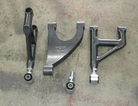 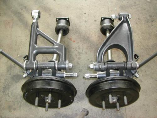 krissto krissto was happy enough for them to follow this design but I was struggling to build such and have my name on it. So this is what I am doing - 45 degrees tubes are from tube-bender - tube-bender.co.uk/ used Tom for the repairs to my Stratos and tubes for the cage in the G15's 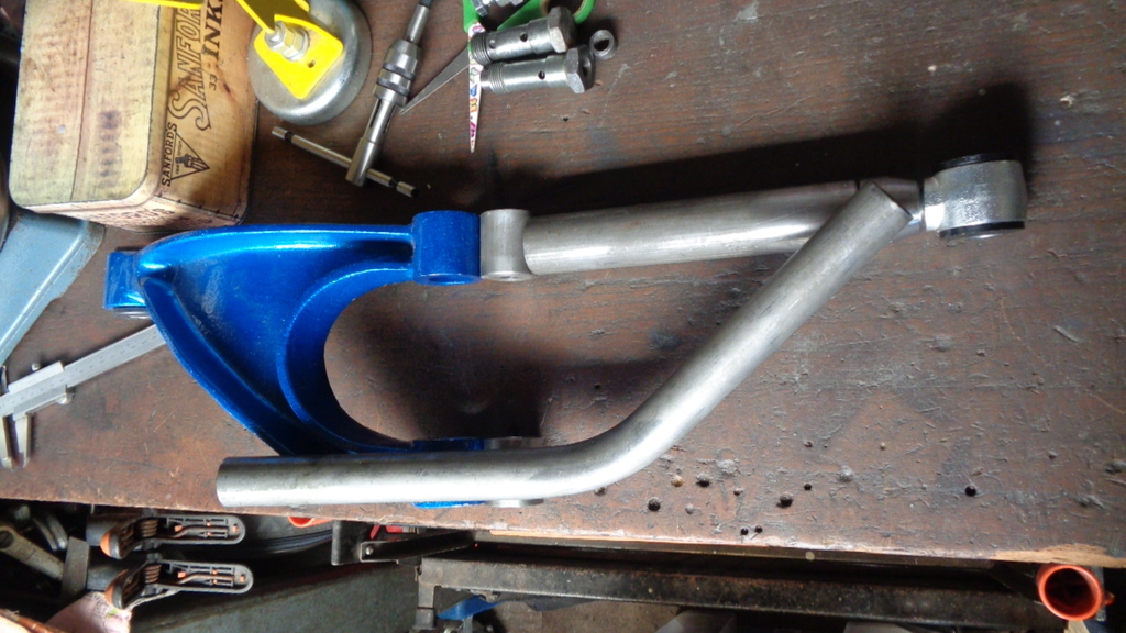 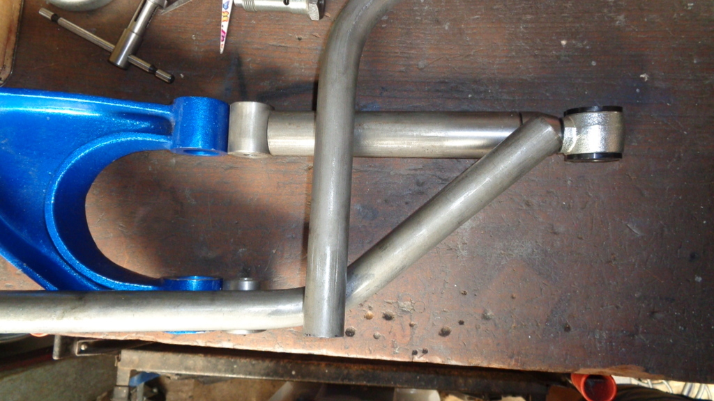 The Cross tube may end up in 7/8 CDS - not decided on that yet Jig build next |
| |
|
|
|
|
|
Jun 15, 2021 23:07:00 GMT
|
Neat! Looking good to me  |
| |
|
|
|
|
|
Jun 16, 2021 10:04:32 GMT
|
|
Thanks Darkspeed.
|
| |
|
|
Darkspeed
Club Retro Rides Member
Posts: 4,872
Club RR Member Number: 39
|
|
Jun 26, 2021 20:34:27 GMT
|
Plan this weekend is to get the jig done and most of the weld preps - Has to fit in between stripping the kitchen and gardening ! What the  is the world coming to... Box section ready for welding together for the jig 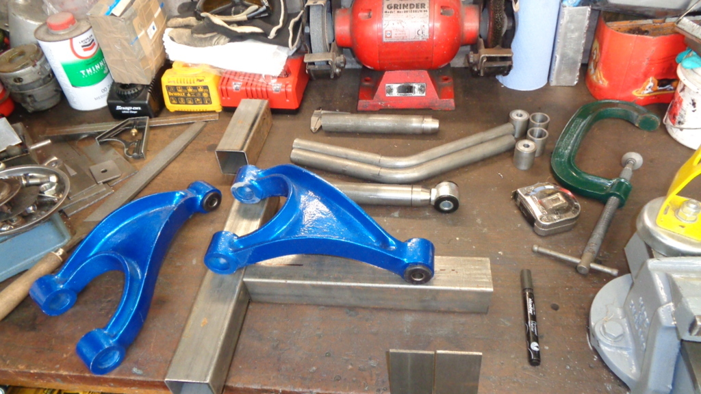 Steel strip for tabs 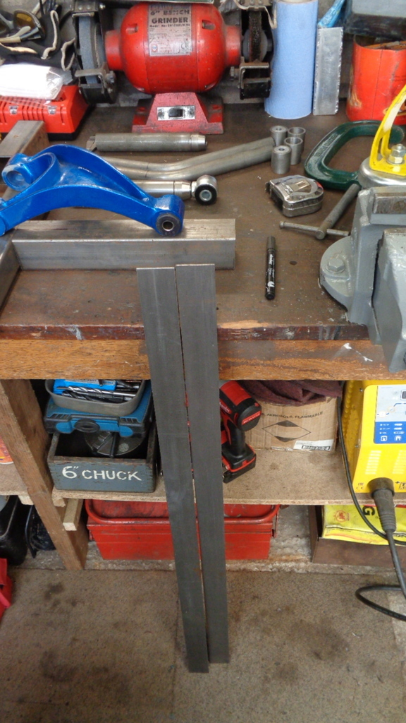 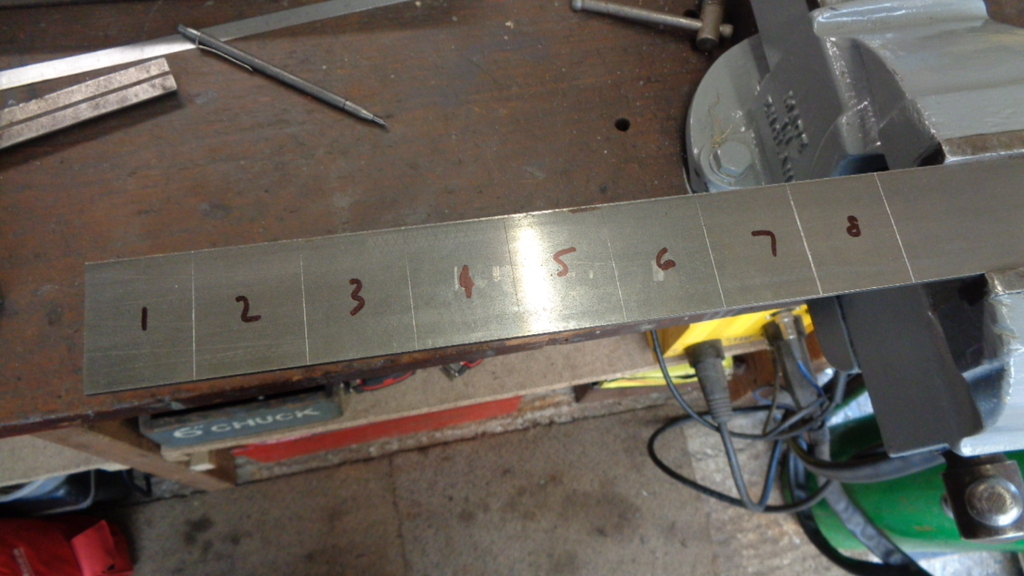 Nearly done 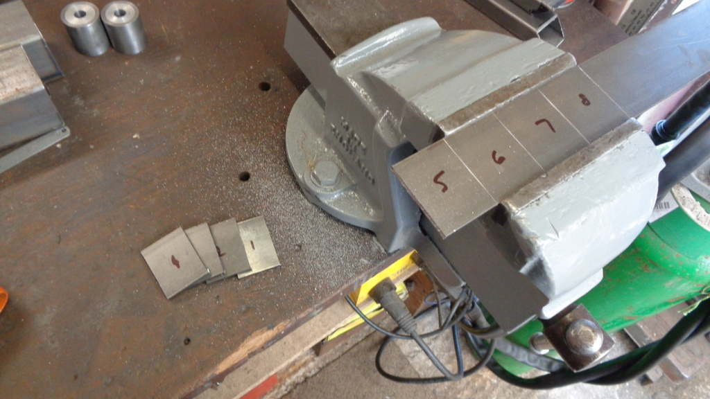 Done 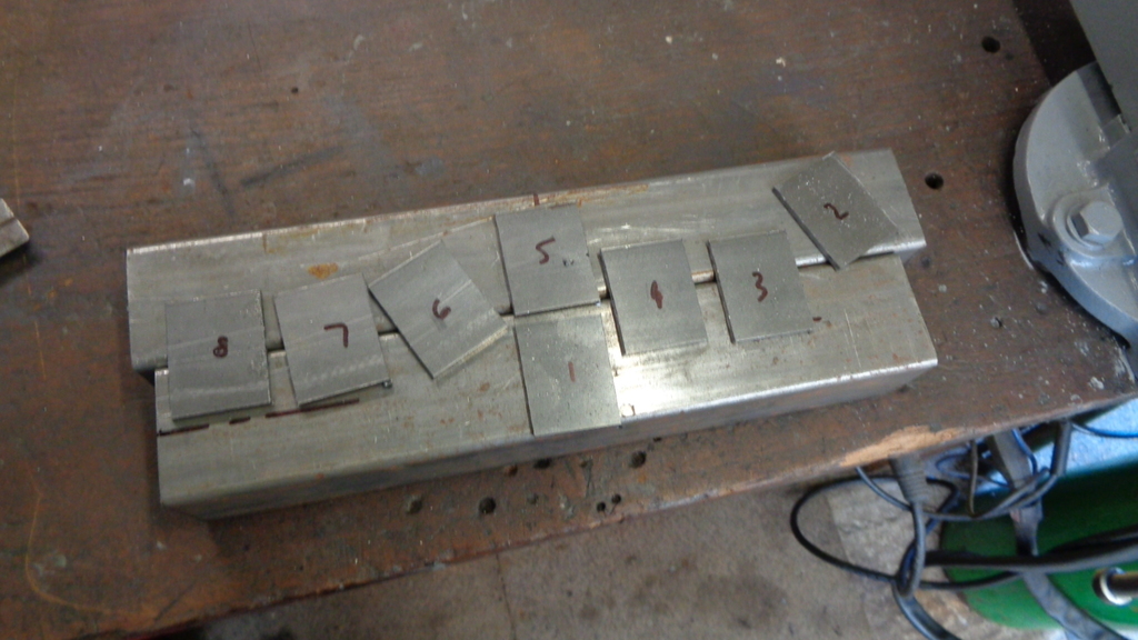 Drilling and welding next - early start tomorrow then  |
| |
|
|
|
|
|
|
|
|
Excellent progress - thanks. My rear caliper brackets were collected yesterday, but need a light ream before they will fit correctly. Then they will be dropped off at a local company for zinc coating. Looks like the planets will align soon and the car can be reunited with the garage floor. I really appreciate the hard work, Darkspeed.
|
| |
|
|
Darkspeed
Club Retro Rides Member
Posts: 4,872
Club RR Member Number: 39
|
|
Jun 27, 2021 18:54:47 GMT
|
Jig - Almost takes as long to make these things than it does the actual wishbones. Holes 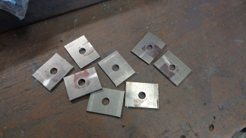 Jig foundation 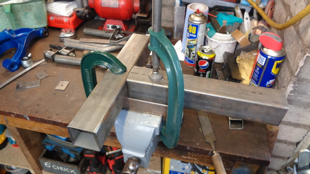 Tabs aligned 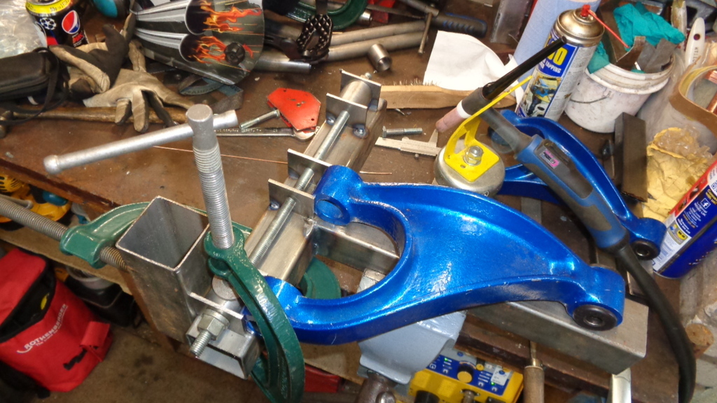 Lets do some measuring and calculating 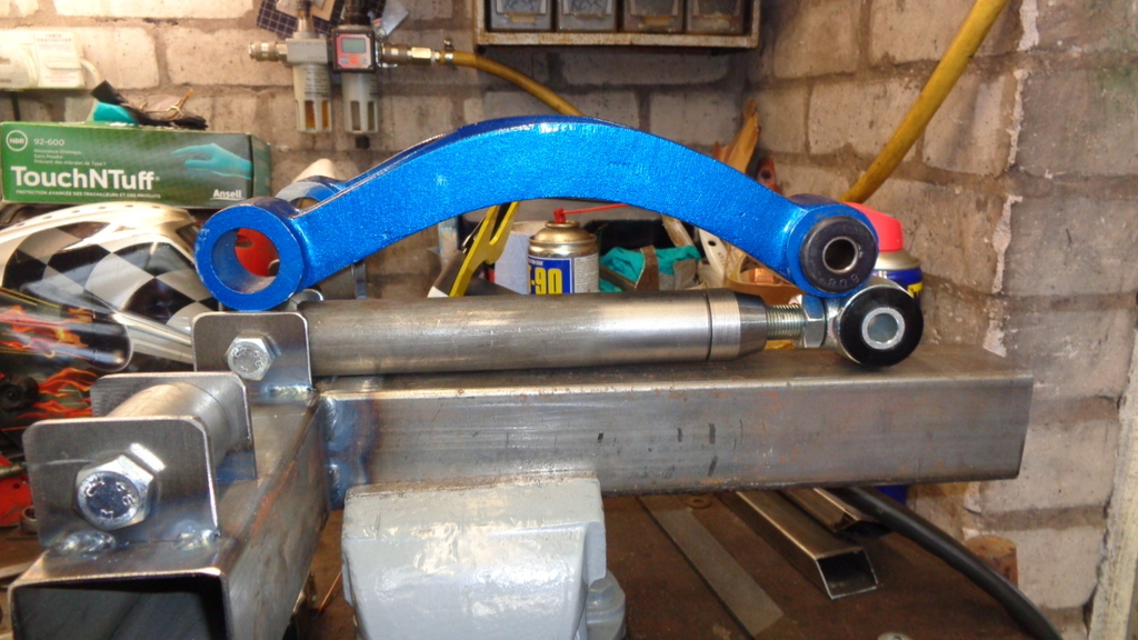 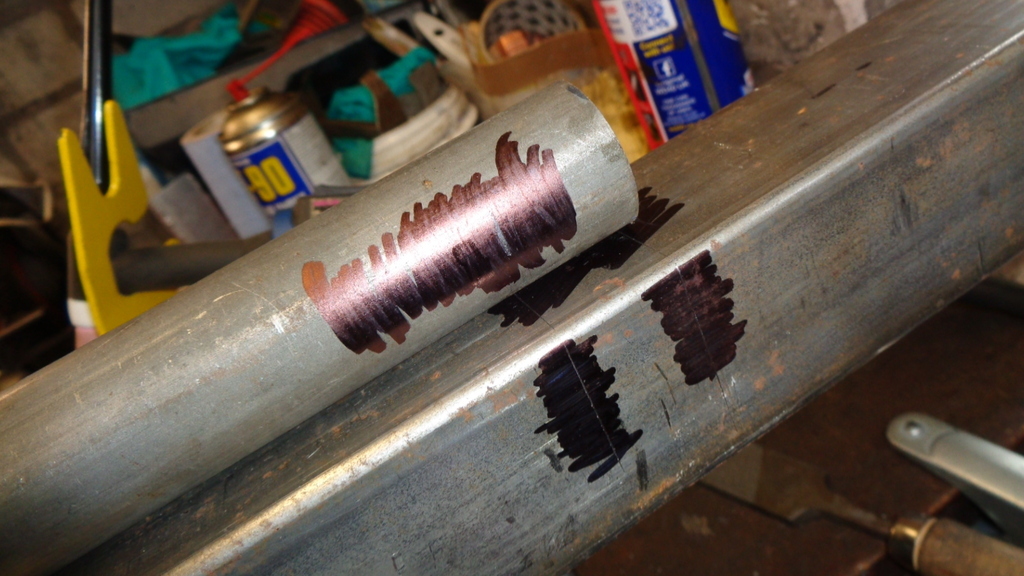 Notch the tube 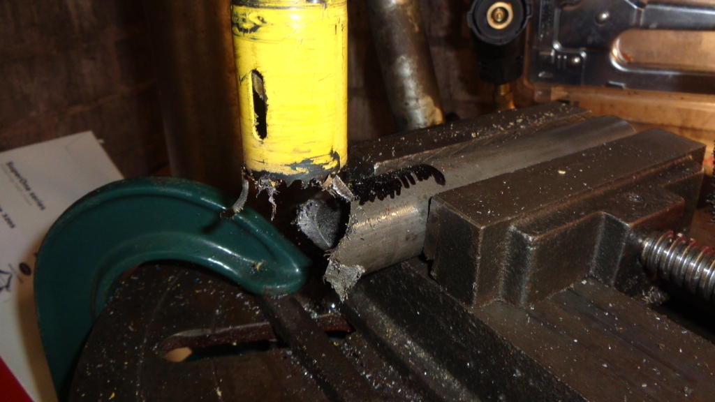 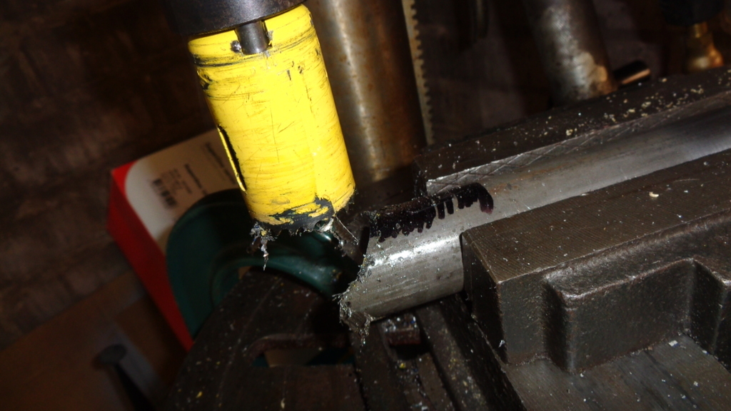 Clean it up and check the fit 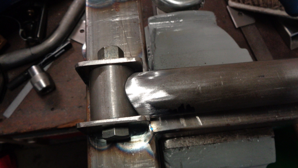 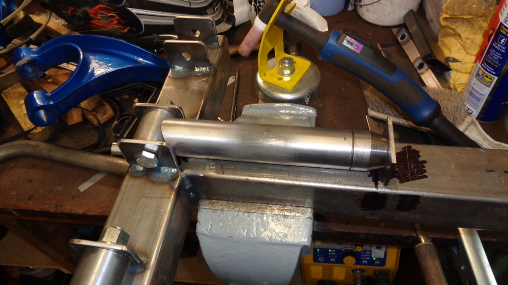 Check that its all as expected 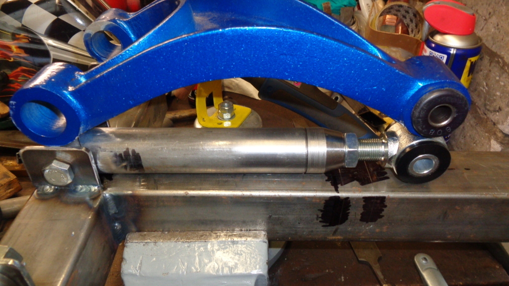 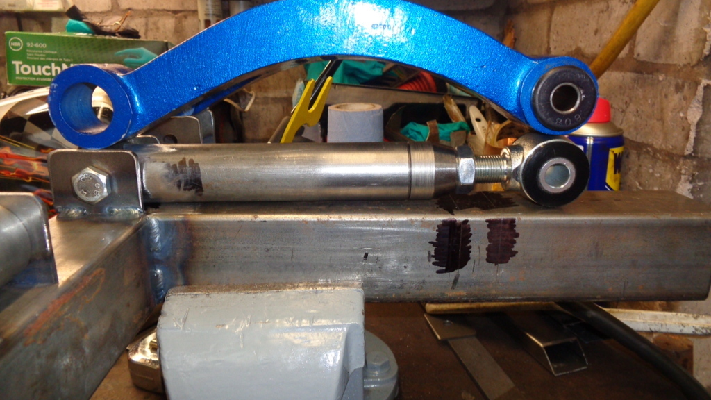 All meets the expectations of the paper calculations. Next stage is to complete the jig with a main tube end stop - notch the other main tube - Notch the 1" and fit a couple of supports as the 1" will need to be raised 1/8 - probably require a couple of diagonals on the jig. |
| |
|
|
Darkspeed
Club Retro Rides Member
Posts: 4,872
Club RR Member Number: 39
|
|
Jun 30, 2021 22:15:35 GMT
|
Had a right old game trying to find the right size UNF bolt to finish the jig - Was almost at the point of having to order one. Let the pictures speak - Tacked up and waiting for diagonals on the jig and the 1" leg 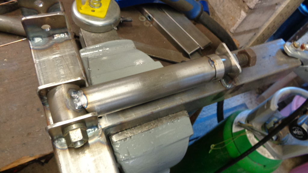 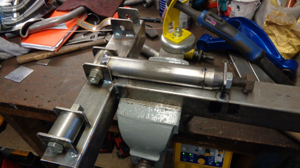 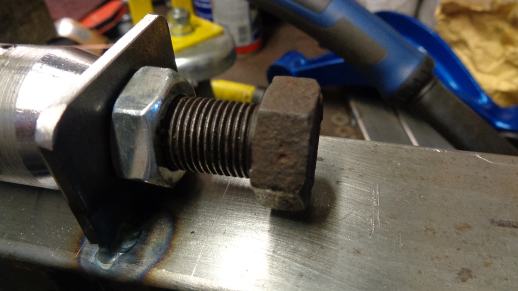 Checking checking checking 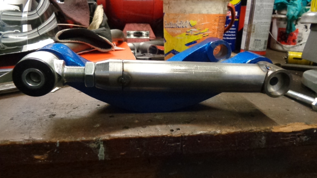 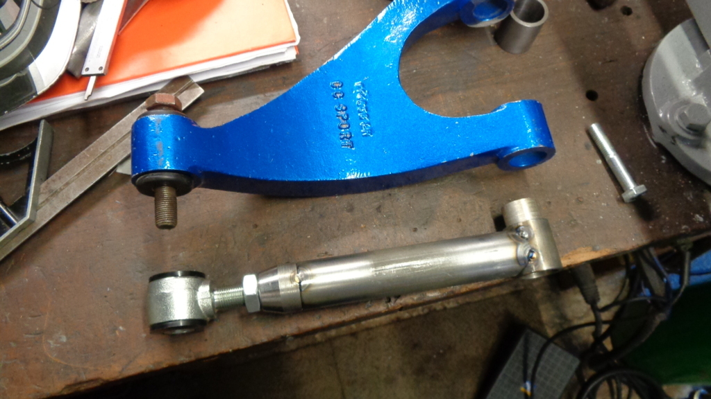 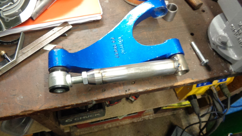 Cheers |
| |
|
|
|
|


 is the world coming to...


