16grit
Part of things
 
Posts: 216
|
|
|
|
If I’m honest I wasn’t liking the look of those ally shims . Bet you weren’t either if truth be told. And you know how it is, I got to thinking, and tried a few things. Now one thing I had never done, least of all before I got the shiny metal out to play with last weekend, was to check the hole positions on the two Empi gearbox mounts against each other. Undoubtedly there’s a ‘lesson to be learned ‘ from my failure to check this out (so excuse me while I stare out the window while I tell you the next bit) ...and I’m sure you’re already there before me, but yes, the two different Empi mounts -hard vs soft - have different hole positions - and in my eagerness to bin the solid mount on favour of something that might lessen the transmission of vibrations to the eh hmmm, seat base areas just a few inches away from where one day hopefully I will be sat, id involved myself in a nasty excursion into the world of engine droop...any kind of droop, as we all know, being ‘sun-optimal’ by simply bolting up the soft mount without checking back against the solid mount.....There-s actually a difference of around 5-8mm, swinging the bellhousing end of the gearbox up and down on my installation depending on which of the mounts is fitted...
So, back to the solid mount, alley shims cast aside, solid mount back in and measuring stick out...
From the first mockups with the engine attached to the box and sitting on wooden cross-member type supports, I had been able to try the rear bodywork for fit with the engine close to where It was actually going to live. And it fitted! Just. Well almost. The new! Davrian rear bodywork I had was around 2 to 3 or so inches too wide for the car, ..not good and obviously this means work ahead, but more importantly I was able to confirm height and length. The crank pulley is going to sit a few mil inside the rear valance area- lucky, engine cover may need a little tweaking to clear the cam cover.
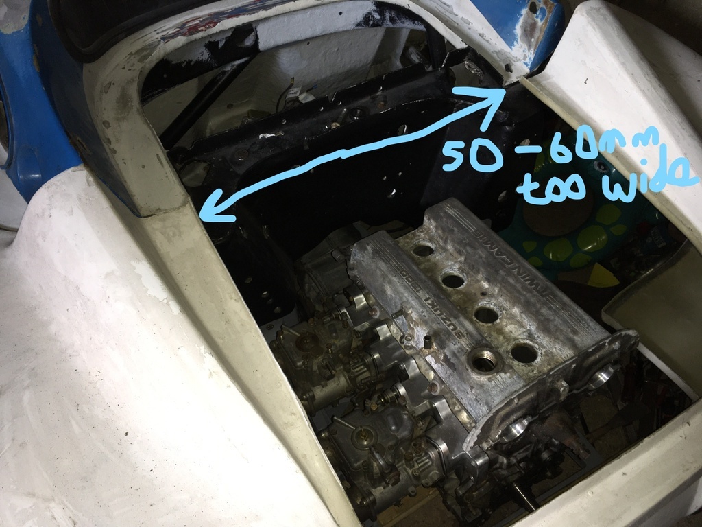
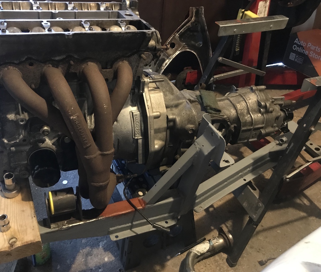
The real job to be done was working about where to place the two engine mounts on the surname / chassis rails, and there was lots going on along the sump line / bottom edge of the block on both sides of the engine, alternator, starter and water rail on the cold (inlet) side, oil filter and exhaust on the hot / exhaust side. I wanted space to be able to accommodate a dry sump pump and the original cast iron manifold as well as the engine mount on that side if I could....the exhaust side mount positioning and the compromises I have had to adopt for this are not pleasing me at the moment, but I’m going to push on and perhaps revisit the exhaust side mount with a different - plate rather than tube - design at a later time....maybe
You get an idea of the issues on the exhaust side in this pic, positioning of mount on this side tricky full stop but more difficult if I wanted to retain use of cast-iron exhaust manifold
OK, so between that photo and now I've been through a house and workshop move, but somewhere along the line I managed to get the two mounts welded to the rear subframe and panic myself about excessive droop while using the soft gearbox mount.
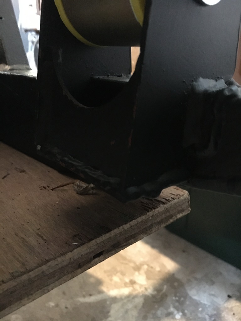
Fast forward til today and I'm happy enough with where the engine and box are sitting to get on with finishing off the tubular engine mount supports that I had started work on. Despite getting the grinder setup in the little cheapo chop saw attachment thing I have I saw the hacksaw and got on with cutting the tube with that....
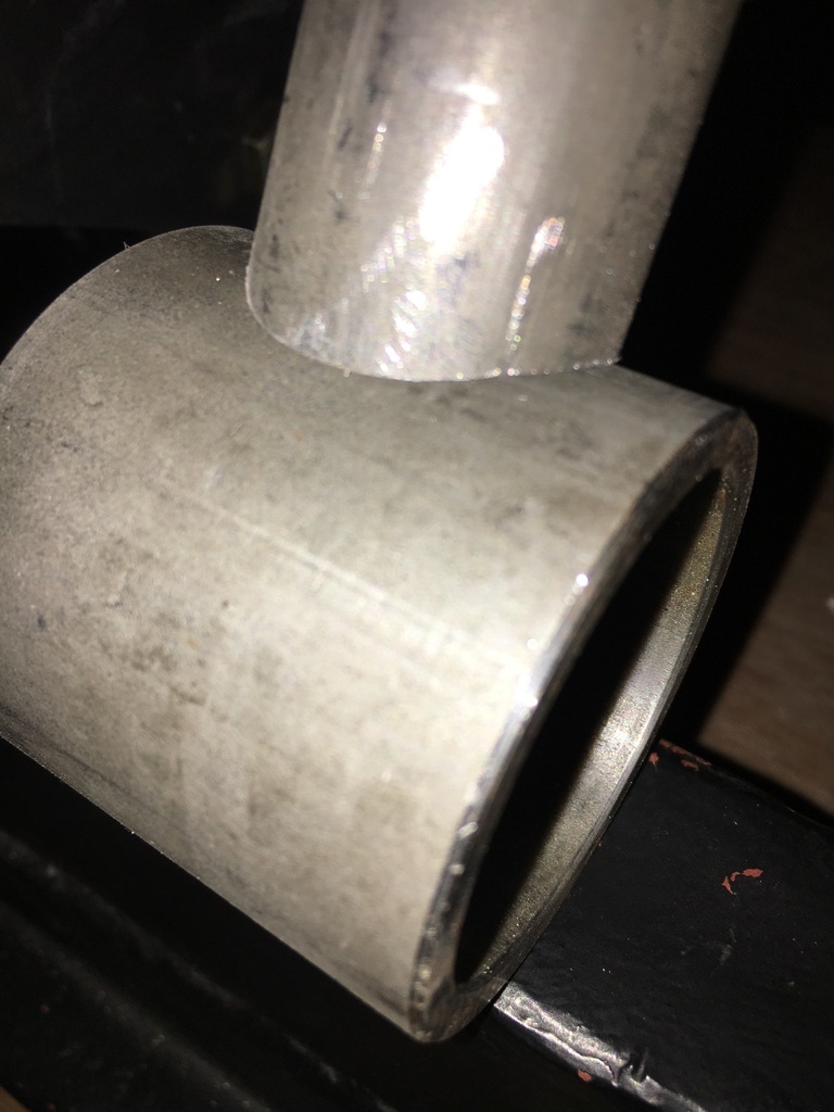
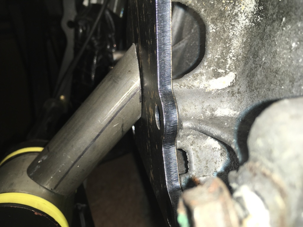
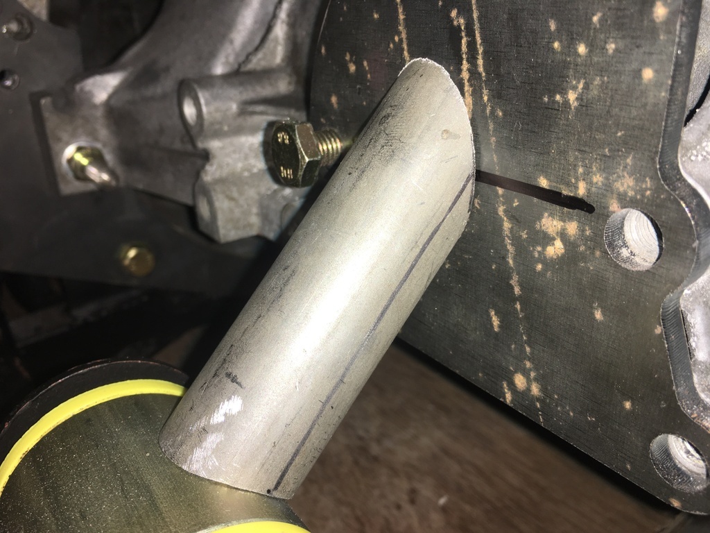
Here's one of the outbound ends I started a few weekends ago...
Hack at work...
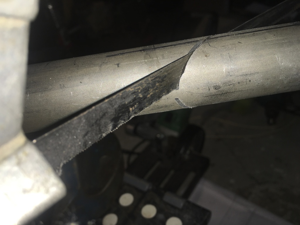 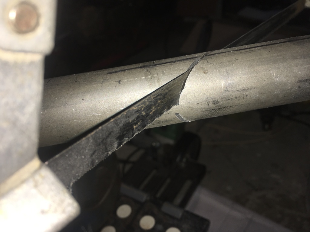
Little bit of fettling.....
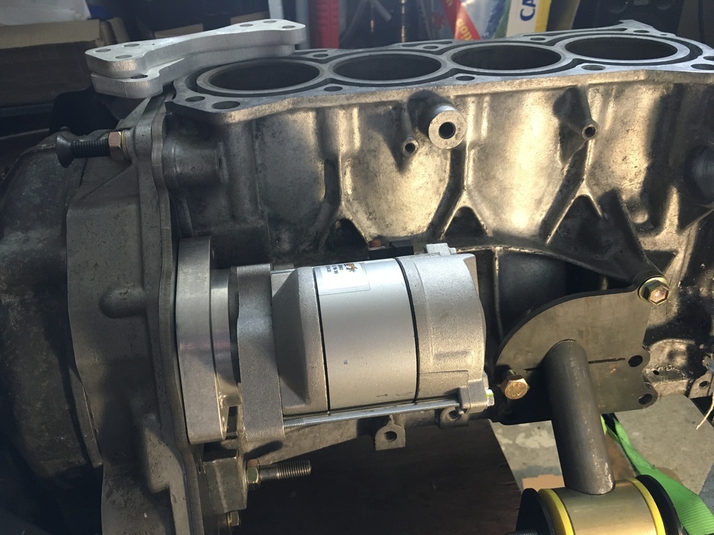
And a pic with the starter added on the bellhousing end, and this is the 'roomier' side of the engine.....
Thanks for dropping by...
|
| |
Last Edit: Jul 3, 2021 12:25:37 GMT by 16grit
|
|
|
|
|
|
16grit
Part of things
 
Posts: 216
|
|
Sept 24, 2021 15:59:00 GMT
|
Thanks for the interest!
Frustrating, but I'm currently on a work stint abroad, so have only been able to get a few drawings done for caliper brackets and some other minor bits and bobs.....
Not many weeks remaining before I'll be free to get into what by then will be a chilly garage I expect!
|
| |
|
|
16grit
Part of things
 
Posts: 216
|
|
Sept 24, 2021 17:10:44 GMT
|
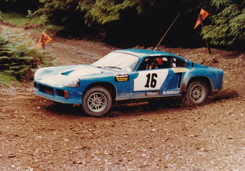
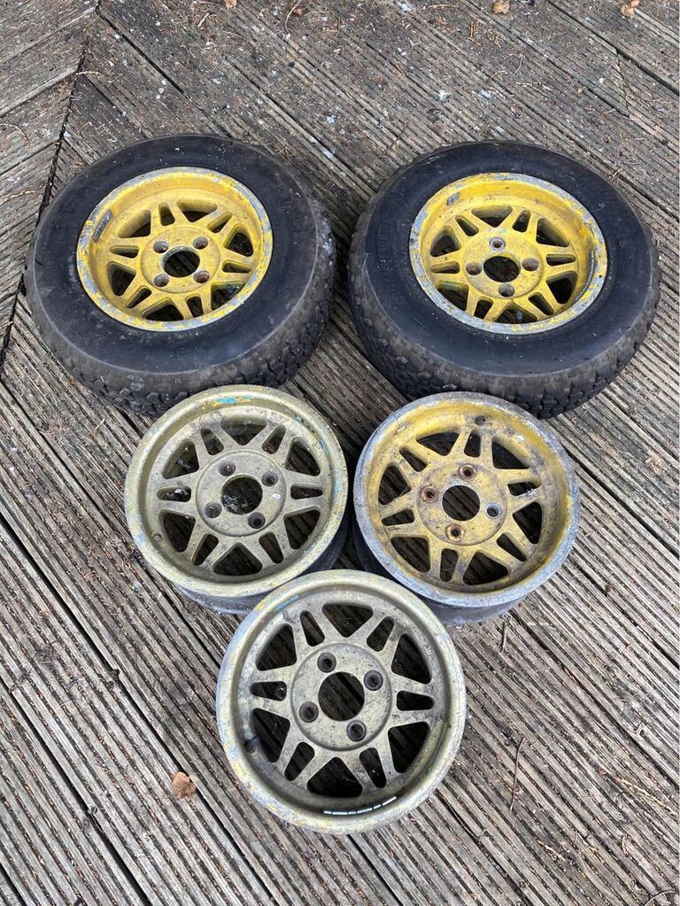
Although I was able to score these a little while back....
In a teary-eyed attempt at recreating this look.....
 |
| |
Last Edit: Sept 24, 2021 17:13:01 GMT by 16grit
|
|
Zagato
Part of things
 
Posts: 80
|
|
Sept 24, 2021 17:52:10 GMT
|
|
Interesting project!
The G13B is a cracking little engine…
It looks much better north/south than it does east/west 😁
I was going to put one in my Suzuki Cappuccino but the 3 pot just kept going! Over 100k miles.
|
| |
1959 Abarth Double Bubble resto project
1989 Lotus Esprit LHD
1997 Lotus Eprtit GT3
1996 Jaguar XJ6 Sovereign manual gearbox from factory
Porsche 356A Coupe replica
Formula 27 Super Seven replica Alfa Nord powered
|
|
16grit
Part of things
 
Posts: 216
|
|
Sept 24, 2021 18:11:53 GMT
|
Interesting project! The G13B is a cracking little engine… It looks much better north/south than it does east/west 😁 I was going to put one in my Suzuki Cappuccino but the 3 pot just kept going! Over 100k miles.
Thanks fella, they offer a pretty good balance between performance and unburstability, especially for a design that's 35 years old and probably a 'classic' in its own right.
|
| |
|
|
16grit
Part of things
 
Posts: 216
|
|
Oct 31, 2021 19:06:19 GMT
|
Able to spend a little time on the car today, didn't get as far as I wished and a little concerned with my glacial progress at present but something is better than nothing. Really wanted to tie the engine mounts up and have nearly got there, one side complete (although not pretty) and the side pictured here well on its way.. Need to take some time here to maintain its fit and keep a grip on distortion as I go. 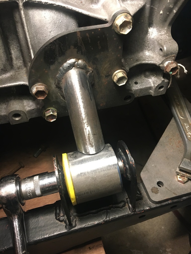 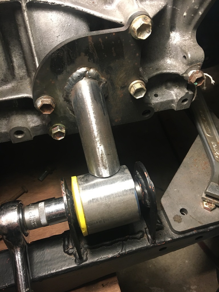 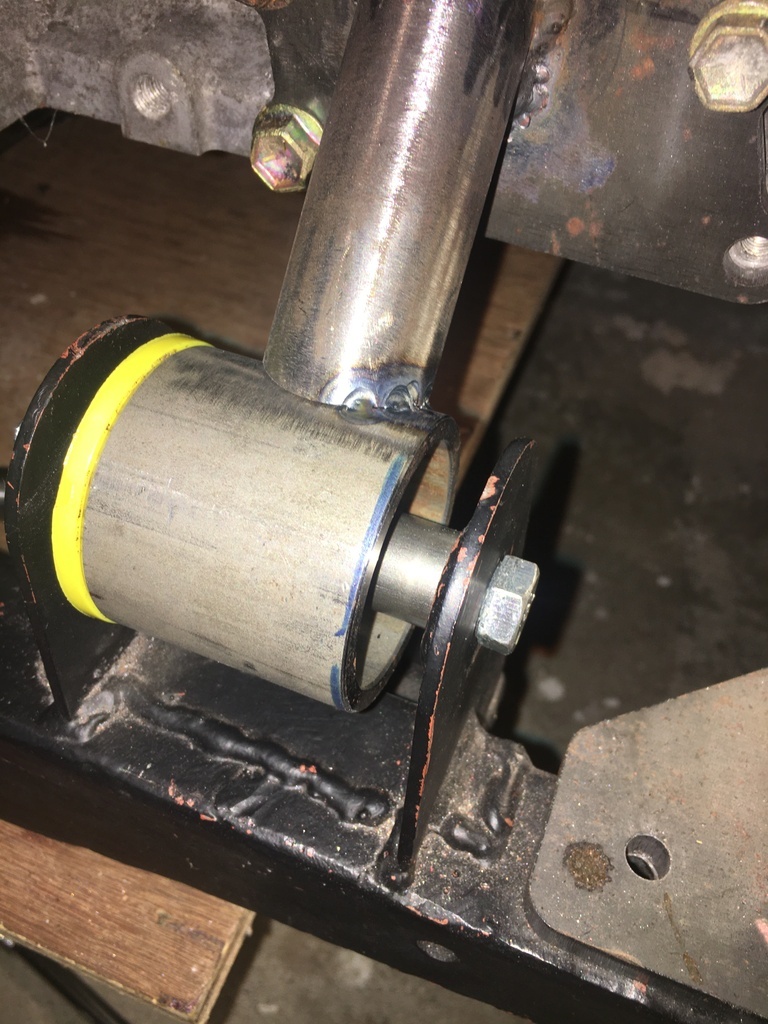 Once the mounts are finished I am going to have a (probably too ambitious) go at an exhaust manifold...but I think that may have to wait for the run-up to the xmas hols now.. |
| |
|
|
pptom
Part of things
 
Posts: 475 
|
|
|
|
|
I was debating the exhaust manifold for my G13b Midget. I have a drawing file for the flange which I was going to get cut. In the end I went for one of those Chinese turbo manifolds, think it was £110 delivered (flange laser cut alone was about £60). It had to be milled flat as it had obviously warped when they welded the pipes on, but other than that I'm very happy with it for the money. Cheaper than buying the bits and making my own, plus, it exits straight down, so easy to take it forward / backward as required.
Just looking at your engine mounts, the bits you've made look good though I'd be tempted to gusset / reinforce the existing upright bits on the chassis, but then I do like to over engineer things!
|
| |
Last Edit: Nov 1, 2021 7:50:28 GMT by pptom
|
|
16grit
Part of things
 
Posts: 216
|
|
|
|
I was debating the exhaust manifold for my G13b Midget. I have a drawing file for the flange which I was going to get cut. In the end I went for one of those Chinese turbo manifolds, think it was £110 delivered (flange laser cut alone was about £60). It had to be milled flat as it had obviously warped when they welded the pipes on, but other than that I'm very happy with it for the money. Cheaper than buying the bits and making my own, plus, it exits straight down, so easy to take it forward / backward as required. Just looking at your engine mounts, the bits you've made look good though I'd be tempted to gusset / reinforce the existing upright bits on the chassis, but then I do like to over engineer things!
Thanks for the comments.
Yep those Chinese turbo manifolds are certainly difficult to ignore at that price. My own turbo 'aspirations' (ok, it's Monday morning!) involve keeping the standard cast iron manifold and then fabricating a short stainless section to hook up with a twin scroll turbo...which may happen sooner rather than later if my experiments with building the N/A manifold that's next on my list doesn't go to plan.
With you 100% on the engine mount bracketry, not really visible in the photos I've posted but mine do have a little more meat to them than the view from the top suggests....
Great to know there's another G13b bod around on here!
|
| |
|
|
16grit
Part of things
 
Posts: 216
|
|
|
|
Quick pic of the exhaust flange I've drawn up for the base of the original cast iron exhaust manifold. This flange was cut in mild and the design has subsequently been tweaked a little. The theory is to have two 180 degree tubes out of this to a VF twinscroll flange. I *think* this might work based on the cylinder division on the original manifold. This is all longer terms stuff really but you know what it's like.... 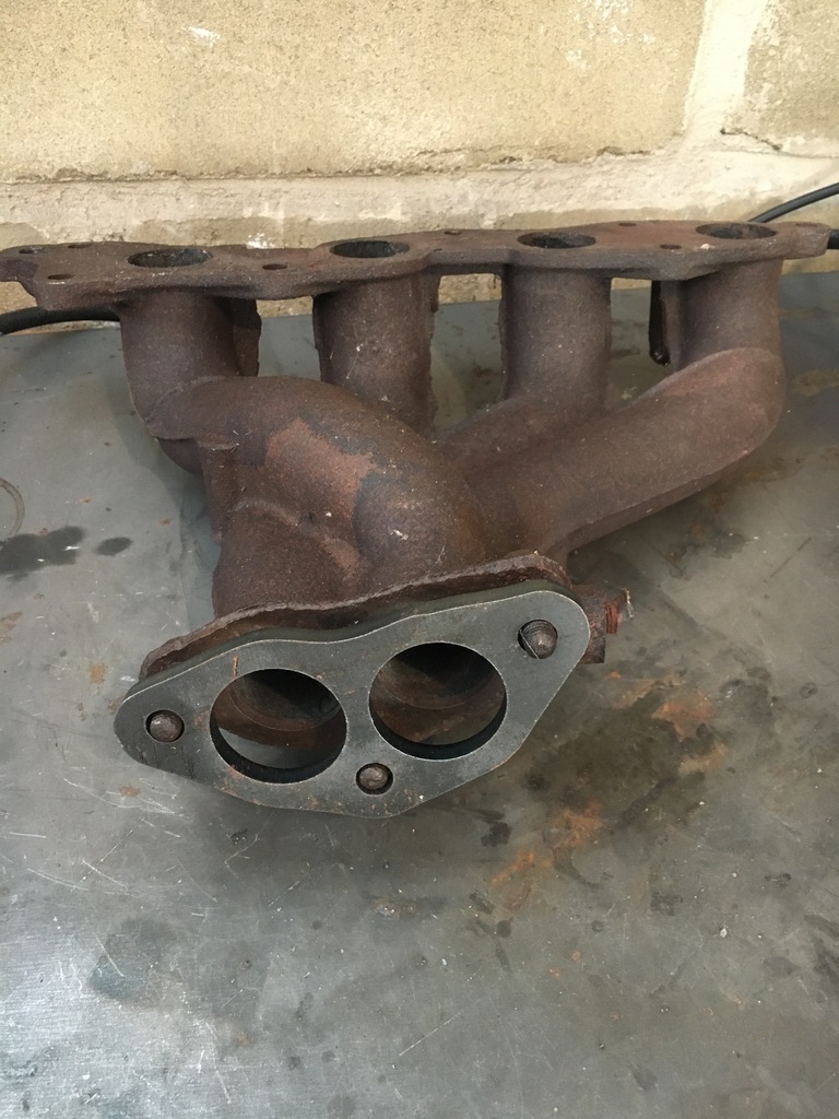 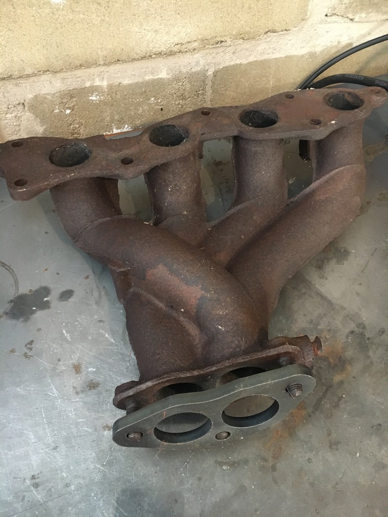 |
| |
|
|
|
|
pptom
Part of things
 
Posts: 475 
|
|
|
|
|
I only had an aftermarket mild manifold from a swift which ended somewhere under the sump, way too rusty to mess with. Although my 'turbo' manifold without a turbo isn't going to be ideal for gasflow, I can't feel any probs with it.
It really is an amazing little Jewell of an engine, I rebuilt mine, and am using the standard inlet / injectors / ECU. Being Ally block I even managed to lift mine out of the boot of my Audi by myself.
I've spent a few years with bikes and I'm happy to say that it's the most motorbike like car Engine I've driven, absolutely loves to rev. Had to do a couple of coolant pipe 'mods' to swap the layout from transverse to longitudinal, and move the alternator to the opposite side to clear my steering column.
Let me know if you want that DWG flange file.
Tom
|
| |
|
|
16grit
Part of things
 
Posts: 216
|
|
|
|
I only had an aftermarket mild manifold from a swift which ended somewhere under the sump, way too rusty to mess with. Although my 'turbo' manifold without a turbo isn't going to be ideal for gasflow, I can't feel any probs with it. It really is an amazing little Jewell of an engine, I rebuilt mine, and am using the standard inlet / injectors / ECU. Being Ally block I even managed to lift mine out of the boot of my Audi by myself. I've spent a few years with bikes and I'm happy to say that it's the most motorbike like car Engine I've driven, absolutely loves to rev. Had to do a couple of coolant pipe 'mods' to swap the layout from transverse to longitudinal, and move the alternator to the opposite side to clear my steering column. Let me know if you want that DWG flange file. Tom You're dead right about the g13s, they are a very light weight unit - and just about manoeuvrable by yourself, which is sometimes very handy! I have a set of Webers for mine, but also am collecting parts to run standalone management with the original hardware as you are using, mainly with an eye to the turbo install.
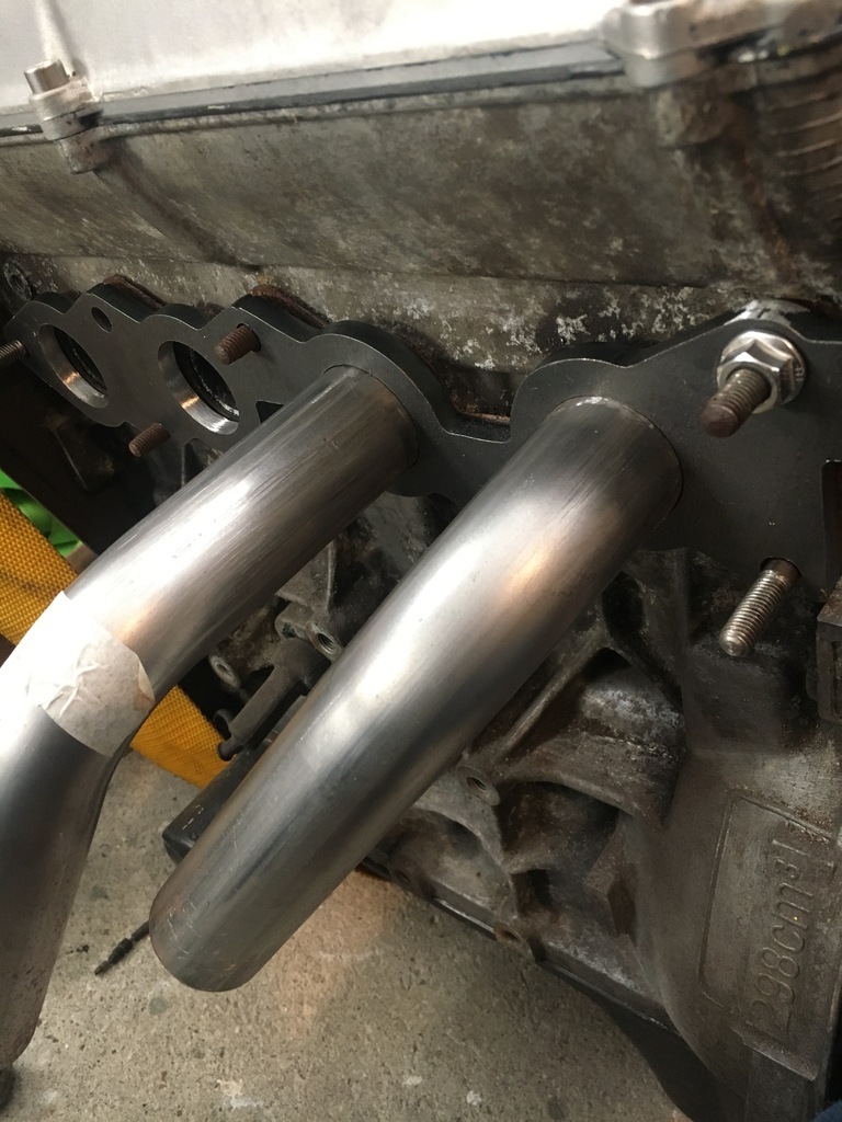
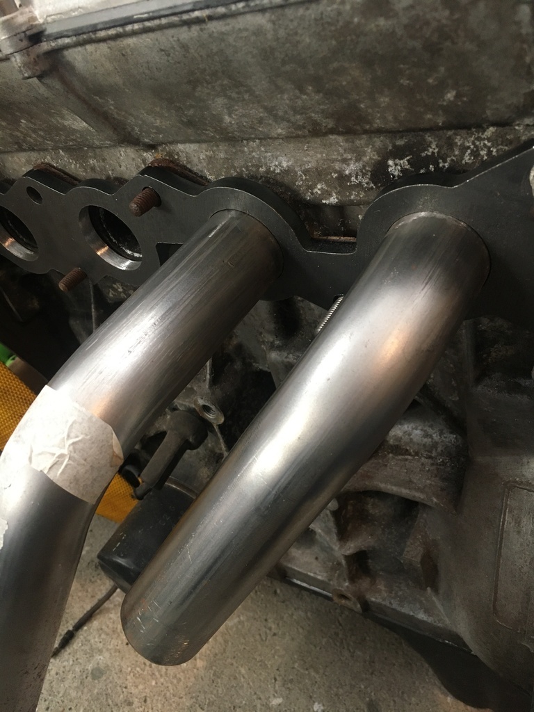
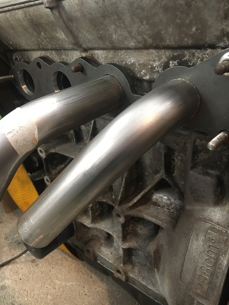
I'm ok on the manifold flange, even if picking it up for this photo reminded me of the looming work if that design is going any further......massive thanks for the offer though, that really is very kind! Have a feeling we could be swapping some notes in future....
   |
| |
|
|
Darkspeed
Club Retro Rides Member
Posts: 4,896
Club RR Member Number: 39
|
1976 Davrian Mark 7aDarkspeed
@darkspeed
Club Retro Rides Member 39
|
|
|
|
Watching with interest as I have - hmmmm.... I was going to say a manifiold for my G27 V8 to do as I will need a larger diam' but as I gave it more thought I need to do the same for another V8 and the Gemini.....
Please make it look easy. - Oh and that it was really cheap.
|
| |
|
|
|
|
|
|
|
|
Seconded on the making it look cheap and easy please. I've got a Rover 2600 that I've never seen an aftermarket manifold for at some point in my future...
|
| |
|
|
16grit
Part of things
 
Posts: 216
|
|
|
|
Cheap and Easy you say?....I can't say with any truth that either of those words came to mind when I took the all-too-rash decision to give attempting to fabricate a manifold a bash....but let's see In a fit of responsibility-avoidance, in terms of actually getting down to the job, today's update consists of my 'interpretation' how the all-too-complicated-looking-theory-of-exhaust-manifold-design might be applied to my little project. I'm sure that there are all kinds of internet based exhaust manifold calculators out there on the web, but cards on the table, my research has consisted of taking a look at my appropriately well-thumbed copy of (four stroke) Performance Tuning in Theory & Practice by A. Graham Bell (whose parents obviously approached the child-rearing task from the very beginning with the necessary degree of jocularity). Dated? Obviously. Flawed? Certainly. To be abandoned after sitting patiently on my bookshelf for the best part of forty years waiting for this moment to arrive in favour of today's flash in the pan internet guru? Absolutely not! It's even got 'figures' in it (remember those?) that are drawn by hand. By hand I say! For the novice disciple of Mr. Bell's exhaust-fabricating-guru wisdom, the quest to achieving manifold nirvana starts, predictably, when you consider the 'holistic' nature of his approach, not with a tube bender and a disc cutter, but by taking a look at your inner exhaust cam, and embarking on a further journey of discovery to get you to a place where you know just how many degrees before bottom dead centre your eight chakras valves start flowing exhaust gas.
Here's my cam set up and being rotated in vee blocks with a dial gauage to see just when those exhaust valves will start moing.
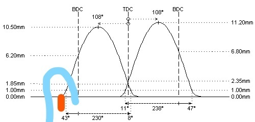
I found this picture on the web which as you can see, contains all the info I need in wonderful detail....It's really easy to guess read off the number we need, because the manufacturer gives us a figure (not the A. Graham Bell book type, the other type) of 43 degrees before 'Bottom Dead Centre' of BDC at 40 thou / 1mm lift. Carefully making it up extrapolaterising, it's apparent the valves achieve lift-off at 55 degrees BBDC. Assuming I'm going to advance the exhaust cam at least 5 degrees (can we talk about that later), the magic number for this part of our quest is thus 60 degrees. Yay!
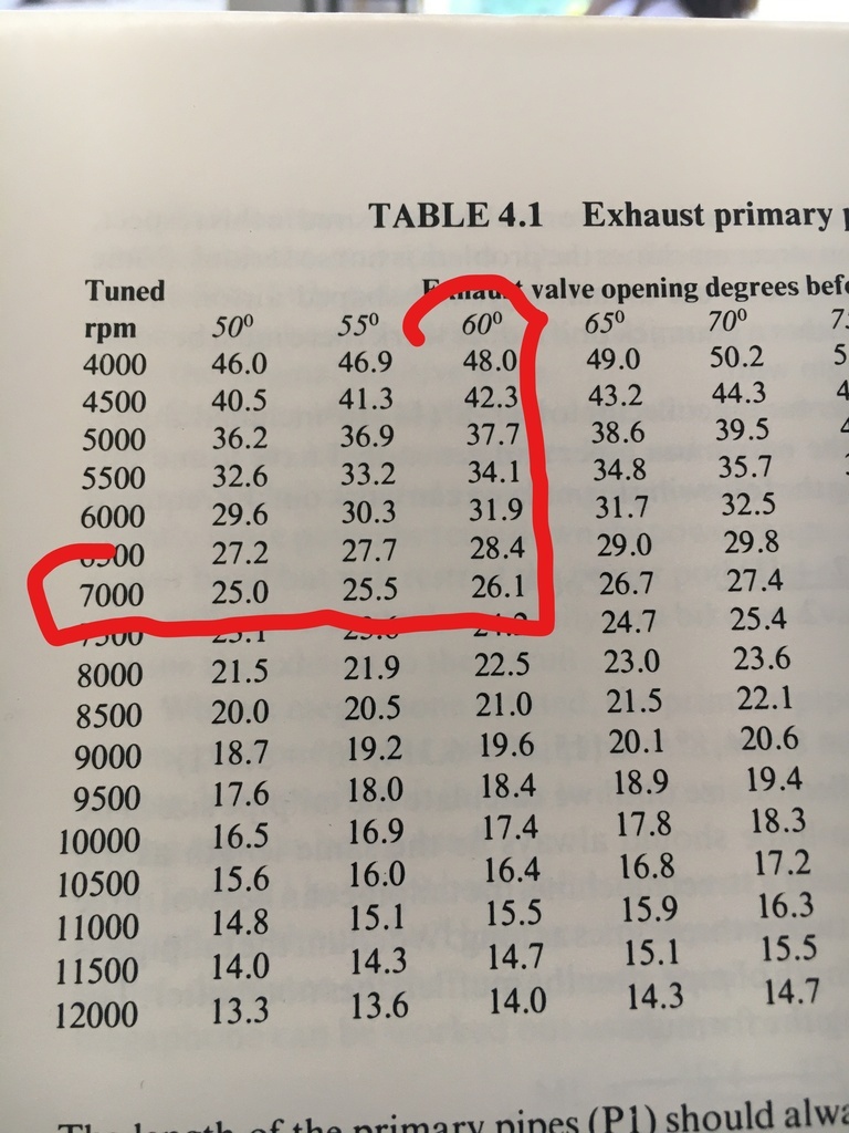
Step 2 in our futile quest is to think about the point in the rev range we are going to tune our exhaust for, and milkman of human kindness Mr. Bell tells us this would be the point of maximum torque in a road engine or the point of maximum power in a race car. Well I don't have either of those, or in fact, a dyno print out with an engine built with those cams in as funnily enough they are lying on my bunch awaiting an exhaust. So more made up numbers and I'm plumping for they dizzying heights of 7000 rpm, knowing this little G13b is a highly strung little filly and guessing that the cams I have aren't going to be happy until around 4000rpm and wanting a realistic peak power redline of 8 and something
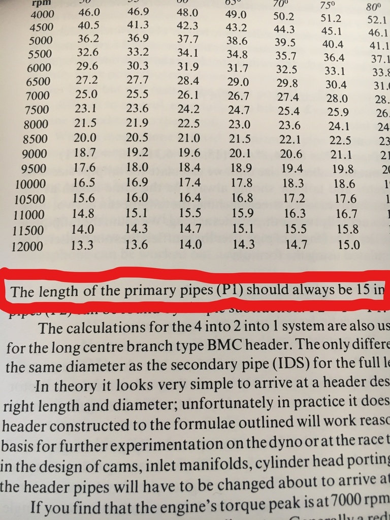
So lets take a look at the parchments of truth Bells book.... and read off the combined length of the 4 into 2 into 1 primaries...
From that then, our total primary manifold length of the whole 4 into 2 into 1 section is going to be 26.1" long...
Now, we all know there are no short-cuts to the truth, but perhaps, just maybe, Guru Bell might have told us from the get-go this little nugget of info......
Yep, that's right kids, just make your 4 into 2 primaries 15" long. That's it. All you need to know! Apparently!
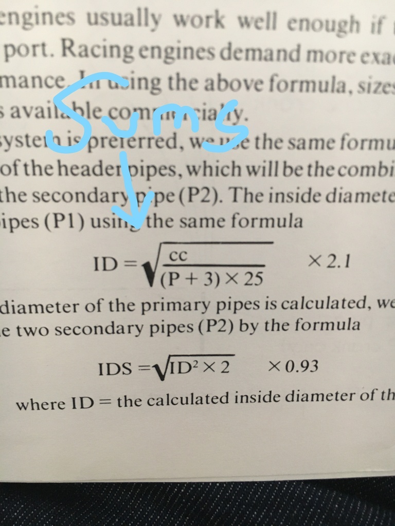
Now, as we approach Manifold Nirvana it should be obvious that the steps of the quest will inevitably become more challenging, and we all know that for booky type people that usually means throwing some 'ard sums on the page, to disorient and confuse us
The maths bit....
Casting those aside with all the verve of Dora the Explora as she pushes vines out of the way before entering Parapatatta....  we get ....
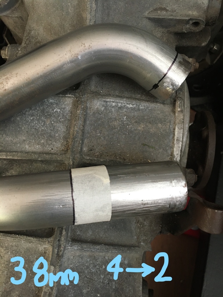
35mm for Internal Diam of the 4 -> 2 primaries, plus 2 x wall thickness of 1.5mm = 38mm OD tube...
And doing the same thing for the 2 - > 1 primaries gives us an ID of 46 or 49mm OD tube or even better, 48mm tube
And finally, tail pipe size, 48mm ID or 51mm OD or what is going to probably end up as 2".....
.........
And then we trot off to ebay and see how those numbers tally up with commonly available tube size and ready-made mandrel bends, coz we can follow our guru whereva, but blind belief gets us only as far as ebay without the real heaven of having my very own tube bender, and so I'm going to have to be content with off the shelf sizes, which is as it should be, when we factor in the very large cloudy-factor in all of this...sorry Mr. Bell
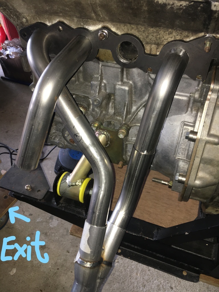
The photo above has been added purely as it actually shows some shiny exhaust tubes, the final product will look nothing like this except that it will include, er, lots of shiny exhaust tube....
Thanks for checking in.... |
| |
Last Edit: Nov 7, 2021 17:00:33 GMT by 16grit
|
|
Darkspeed
Club Retro Rides Member
Posts: 4,896
Club RR Member Number: 39
|
1976 Davrian Mark 7aDarkspeed
@darkspeed
Club Retro Rides Member 39
|
|
|
I think I have a copy of PipeMax around here somewhere from a bundles deal from Spead-talk or somesuch - Will have to see if I can open it up after all these years and see if it works. Probably will need a password I have long forgotten or lost. maxracesoftware.com/PipeMaxPro400.htm |
| |
|
|
16grit
Part of things
 
Posts: 216
|
|
|
|
I think I have a copy of PipeMax around here somewhere from a bundles deal from Spead-talk or somesuch - Will have to see if I can open it up after all these years and see if it works. Probably will need a password I have long forgotten or lost. maxracesoftware.com/PipeMaxPro400.htm
Impressive array of functionality there.....would be fun to compare with Bell's ideas from the 70s...
|
| |
|
|
16grit
Part of things
 
Posts: 216
|
|
Nov 28, 2021 17:57:24 GMT
|
Work commitments have kept me out of the country again, but I have been able to put in a bit of time on the Dav while not eyeing shiny stuff to make a turbo manifold with waiting for exhaust tube to arrive for my N/A exhaust manifold.. One area I have been collecting bits and doing a little here and there as part of other bits is the front anti-roll bar. Here’s a pic of the bar in situ: 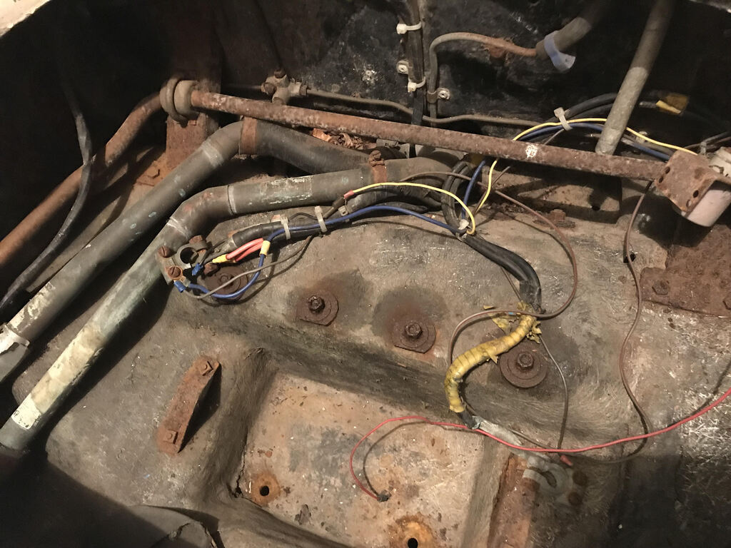 The bends in the bar and the mounting bushes and clamps, although sat on some natty angled fabbed brackets told me that the bits had been sourced from another vehicle, the challenge would be to work out what. The brackets (I thought);reminded me of Renault r5 bits, but a quick google showed me a)I was wrong and b)my memory was not that reliable.... In the end, a thickness of17.3 mm showed me it was an imperial size and copious Googling and I ended up with Triumph Spitfire / GT6 etc..as the most likely origin. The clever bit was how this had been put to use. As you can see from this photo, the end of the bar were connected to drop links going through cutouts in the front boot floor 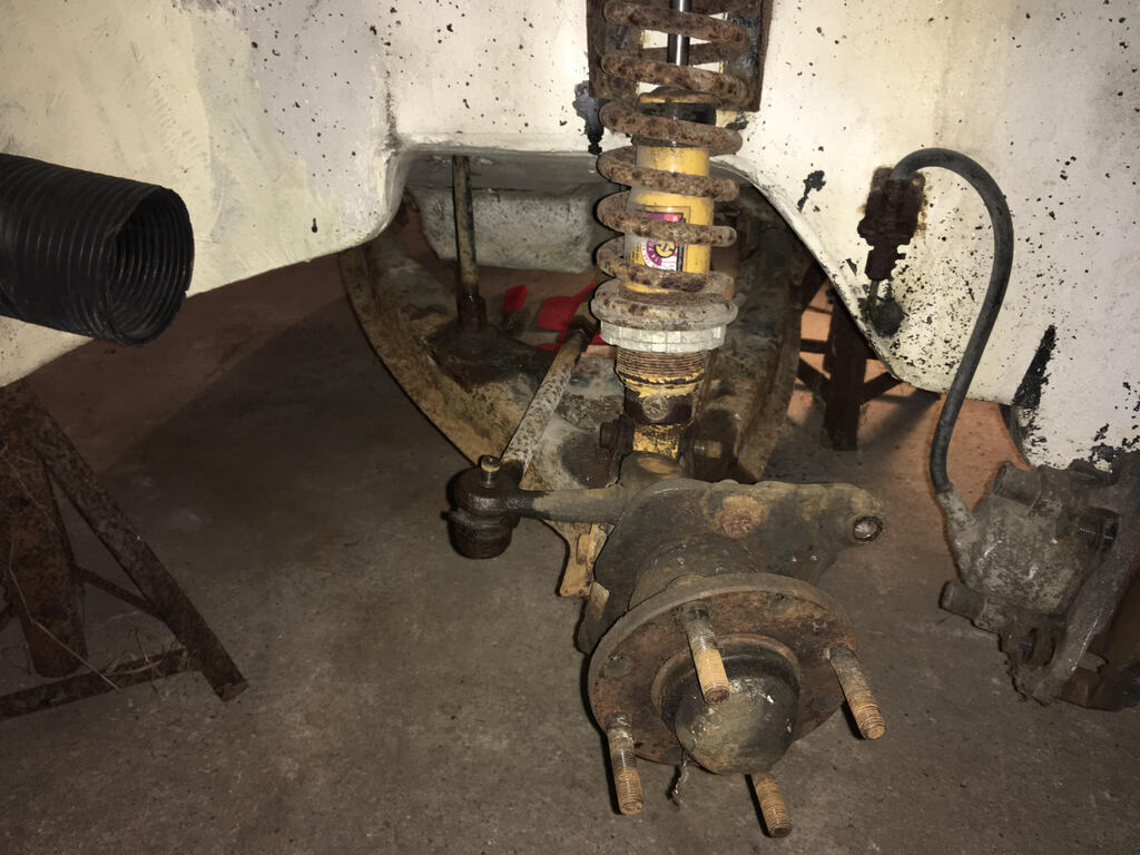 Down to the front arms, strengthened on top and underneath: 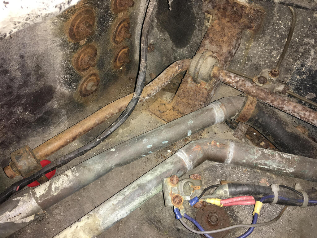 And have subsequently blasted and plated the angled bulkhead mounts and sourced some new bush mounting brackets. I found some Subaru bushes cheap that Imwas going to use, almost solely out of my dislike for brightly coloured poly bushes but having spent time working through this while the kettled boiled the other day, am now comfortable with just buying the correct Spitfire bushes for the clamps and ammresigned to living with their bright orange colour... 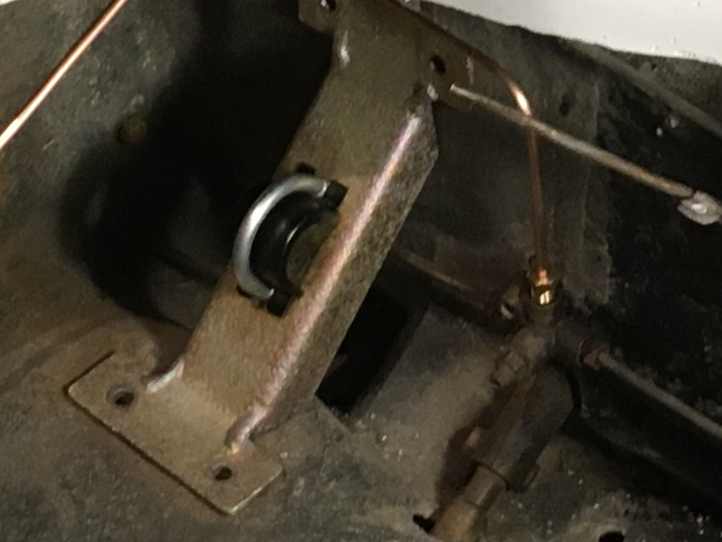 somthat just left the drop arms themselves. Duffy was typically inventive here, using basically what must have been laying on his bench in the form of a couple of steering rack drag links, repurposed by threading them a bit further, adding some shock bushes and cups and some inserts to marry and bolt them up to the bar itself: 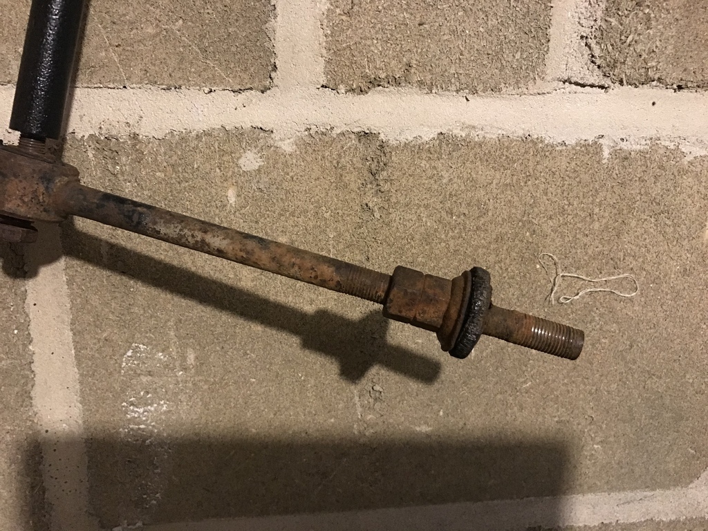 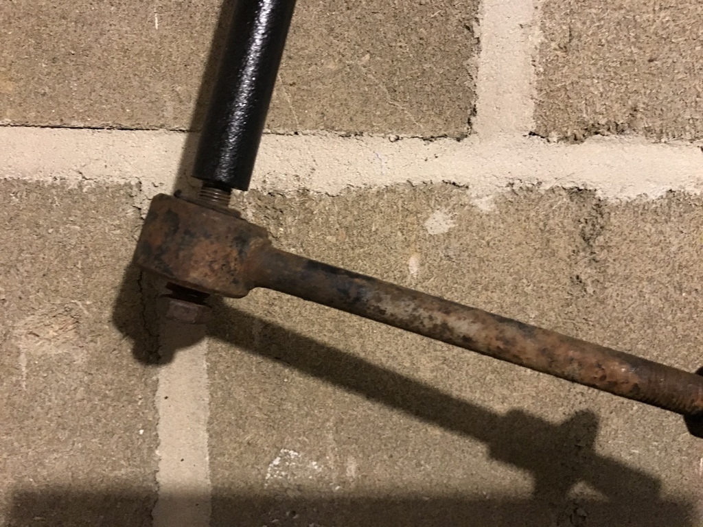 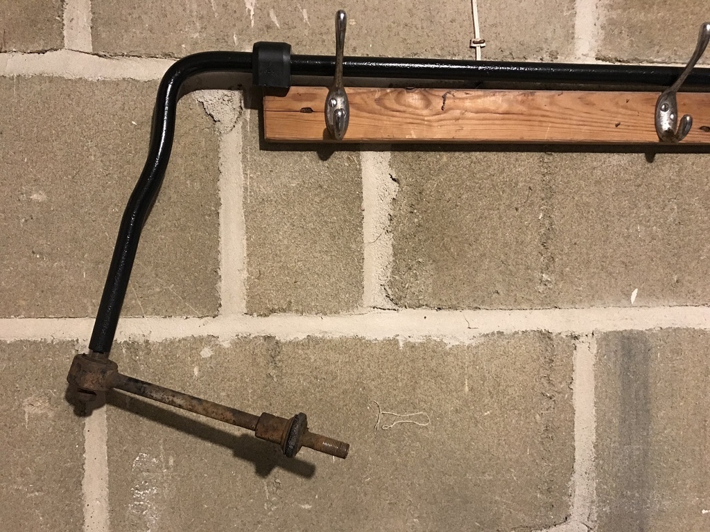 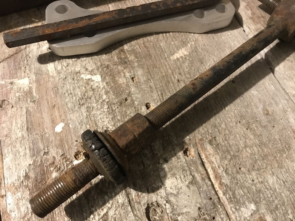 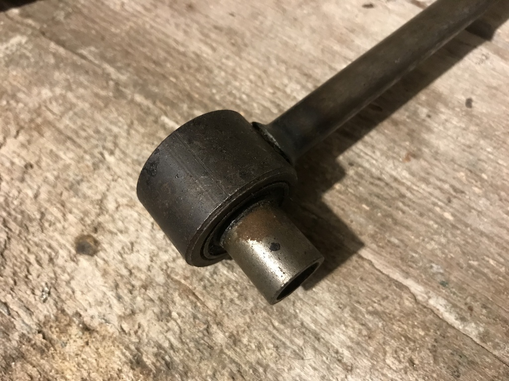 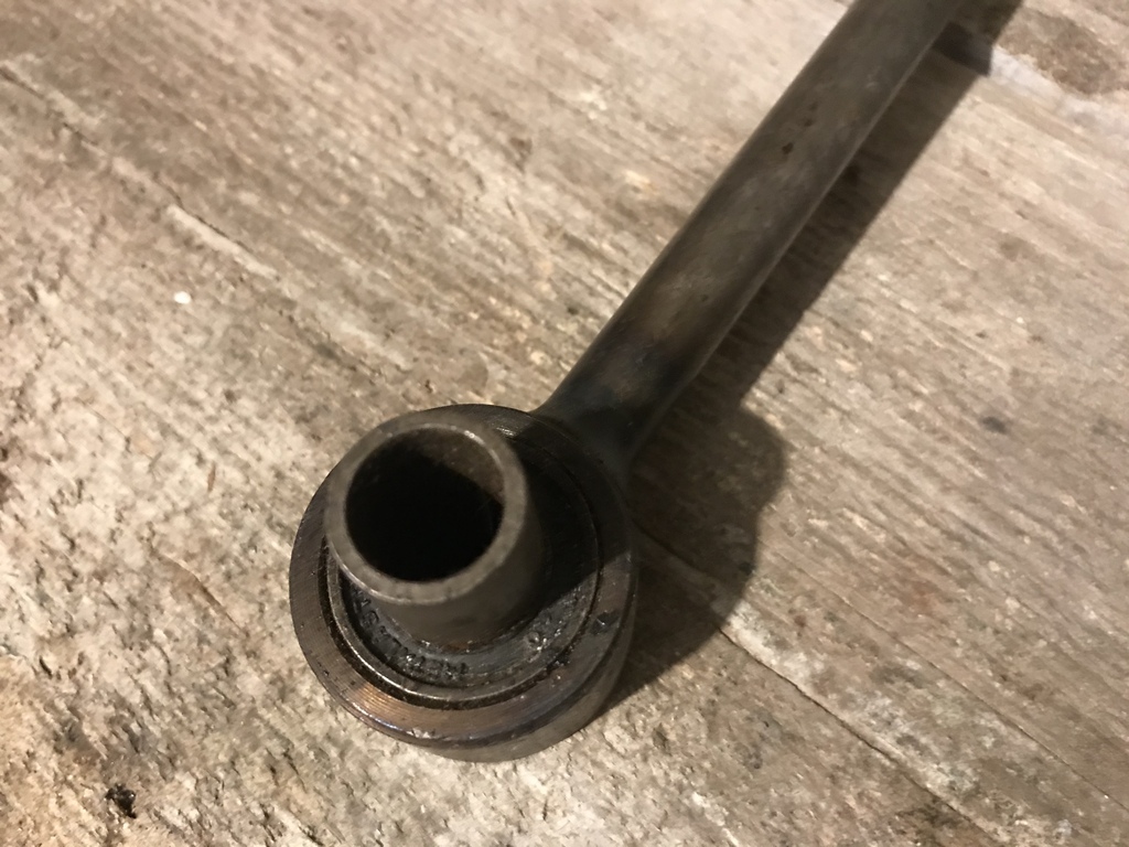 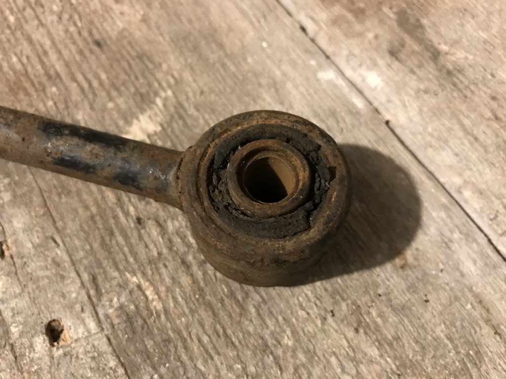 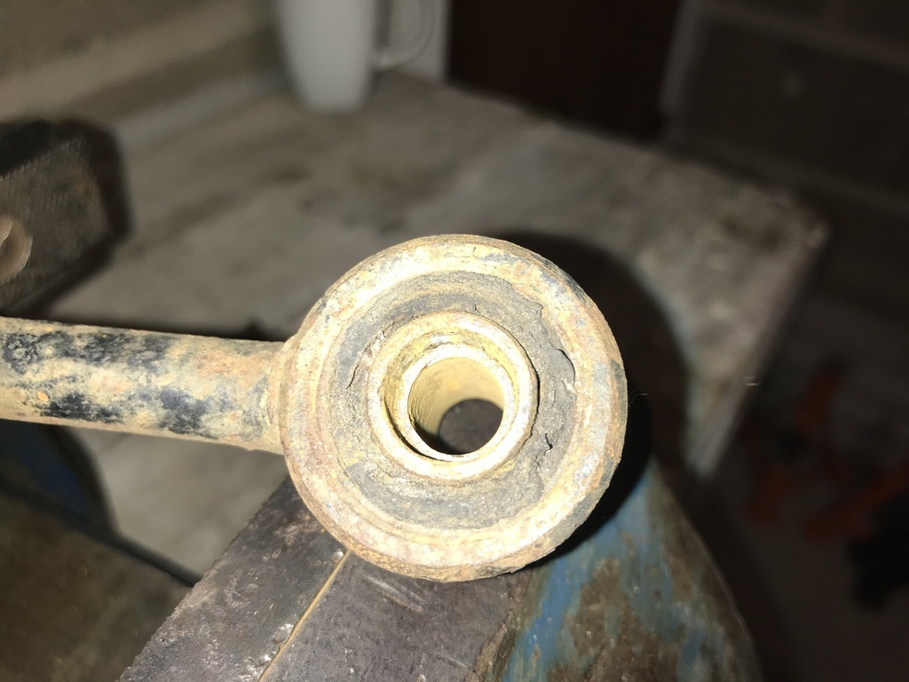 thanks for taking a look |
| |
Last Edit: Jan 30, 2023 19:19:41 GMT by 16grit
|
|
16grit
Part of things
 
Posts: 216
|
|
|
|
Thought it was about time for an update of sorts. My excuse this time around for not making any progress on my exhaust manifold is ........ is.......er.....is..... A complete lack of Argon. Back in November, with the quantity of welding looming, I decided to trade my relatively small argon bottle for the next size up. This would mean a bigger bottle deposit and (slightly) higher but more economical refill charges. Except for whatever reason when I went to my local depot to do the exchange and fill they had no stock of the medium sized bottle required. Mixed with some covid in the house, work trips abroad, quarantine and whatever else, it was only last week that this fella arrived in the garage...
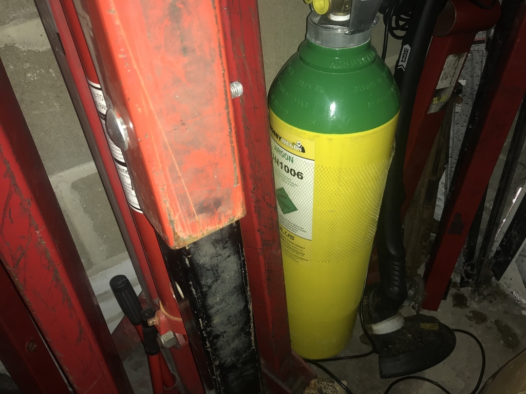
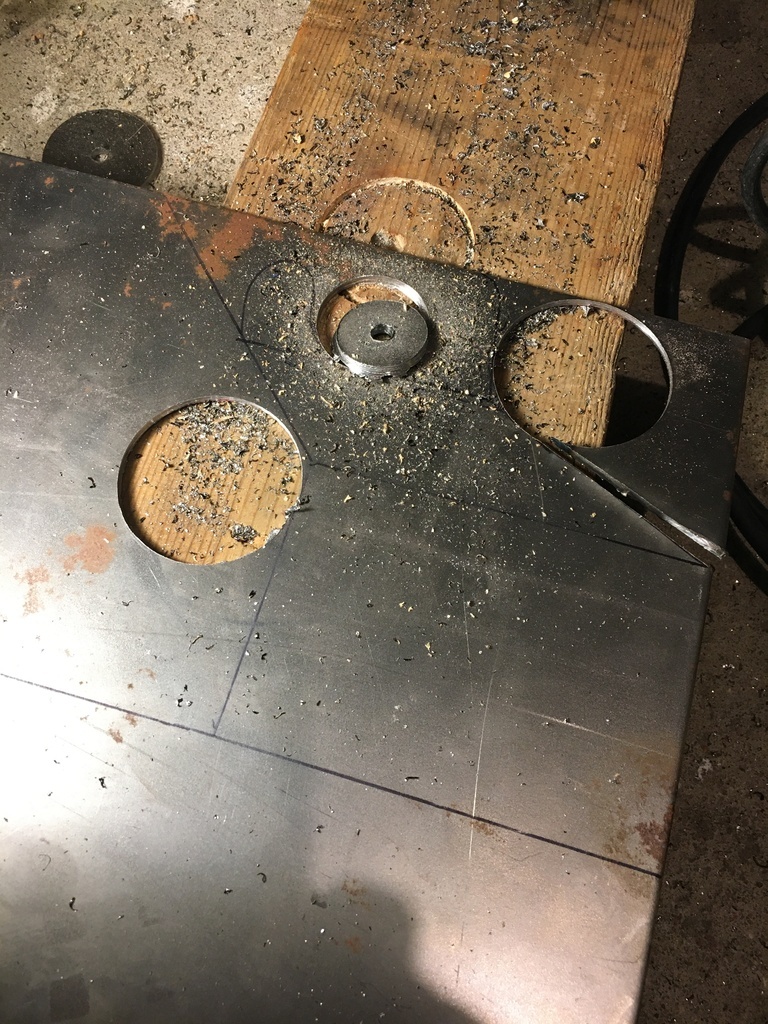
In the meantime, having had a little time to think things through, I 'discovered' I wasn't really ready to make my manifold anyway. And not just on an emotional level. Or a skill-level related one. No, I mean, just on a practical, 'OK, i've made the manifold but what about the silencer..but won't that mean cutting the bodywork....but what about......etc. I can't say how this began for sure - whether this was because I had entered one of those 'cant do this before this is done' loops that maybe some of you will be familiar with, or an 'always know where you are going to put the thing down before you pick the thing up' kind of paralysis or some other form of 'success avoidance'  ....but what it meant in my case was that I saw other things needed doing, not least making a start on thinking about the silencer that was going to hang on the end of this exhaust, where it was going to sit and how it would connect to the manifold. That itself needed a flange cutting, but before pressing the big green steel cutting button on just that flange, I thought I should really finish the sketches for a few other bits that would be needed in the not too distant future too and that these could be cut at the same time...and so it goes on.....
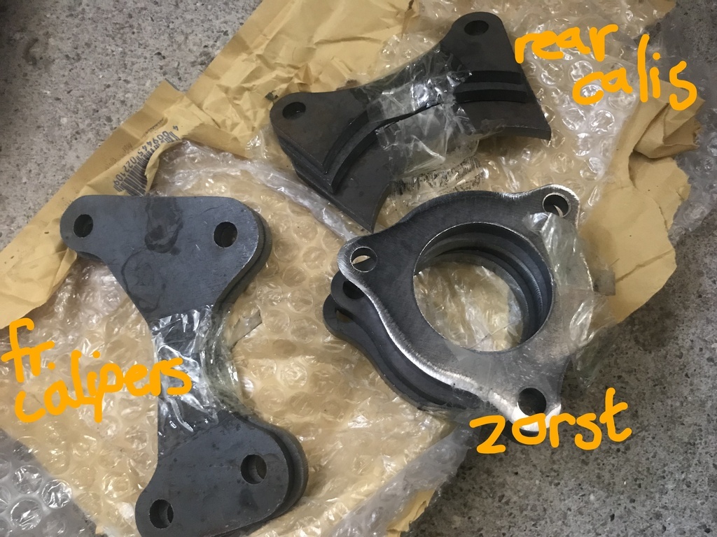
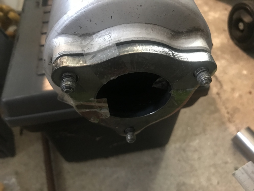
The exhaust flanges shown in that pic destined to fit on (Suzuki branded!!) Hayabusa silencer that I just happened to have kicking around. When I originally dreamed up this bit, I was thinking of some 6R4 style double decker noise-cancelling silencer setup, which may still yet come to pass.....but leaving that, here's a quick pic showing the flange on silencer...
Having decided to mock-up the silencer position, I decided that I would change the engine-block I had sat in the cradle bolted up to the gearbox for the engine I was hoping to be able to use to get the thing to a running stage. This was another mk1 swift gti unit (narrow timing belt, old schule distributor etc), probably rallied and revved to death in a previous life but in one piece and (I'm hoping) capable of starting.....
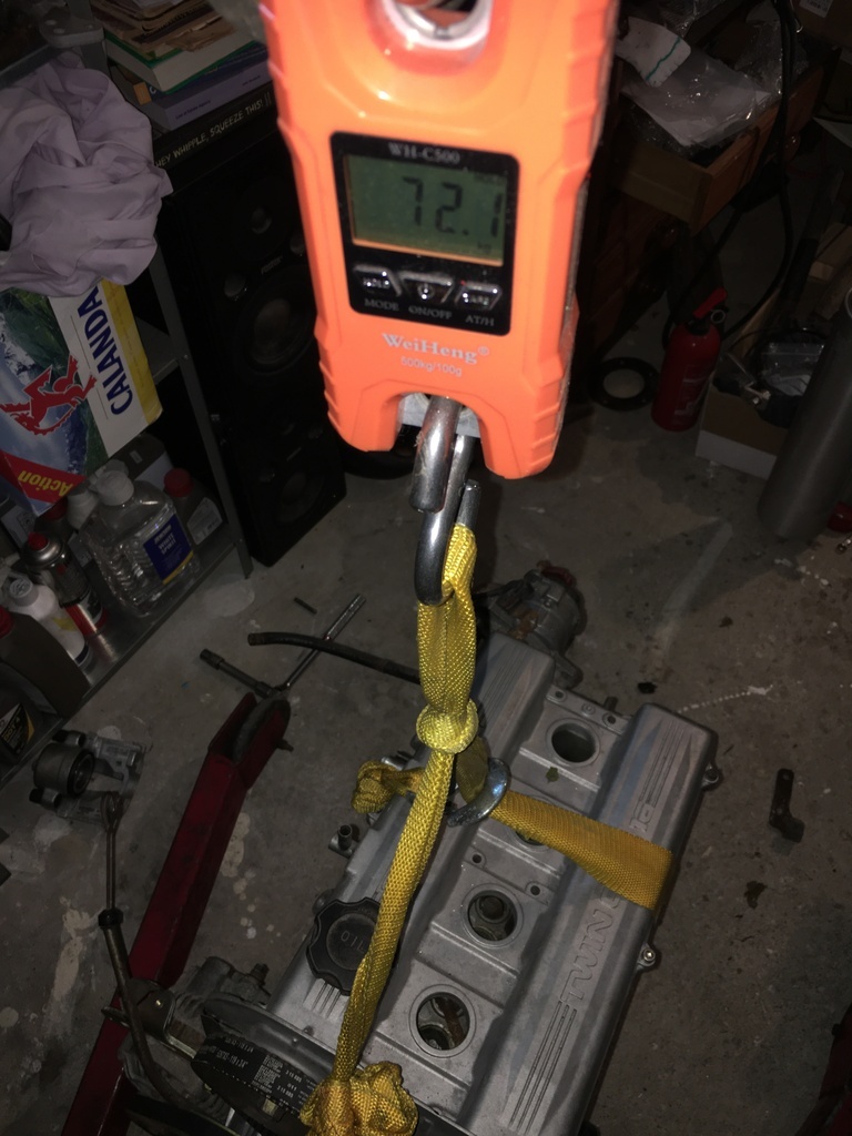
In the middle of swinging the engine into position, I took the chance to weigh it. Not actually as light as I always believed, but still half a small person less than a xflow etc..... 72kg dry, no manifolds.....(obviously.....)
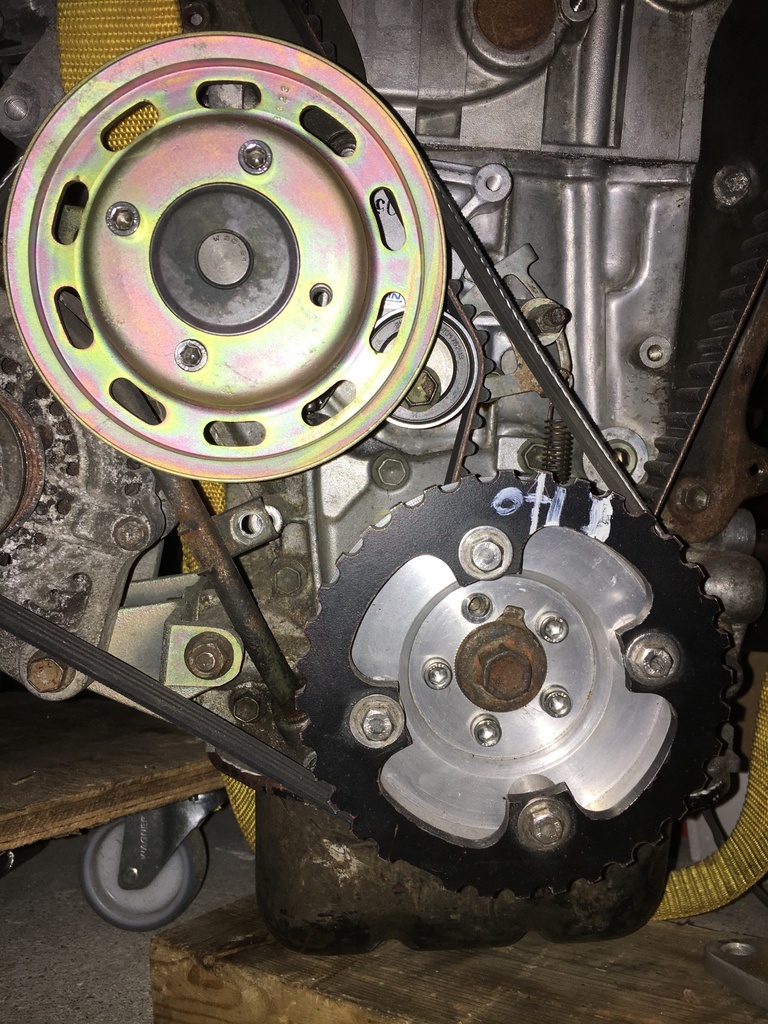
I'd previously fitted a few service items to this engine, put a new belt and tensioner on it etc.
Beyond the gold-tone glare that some on here are already connecting with deep seated 'kitcar' ownership trauma, my eye began to focus on the trigger wheel and the reality that I was going to have to sort my ecu situation out, rather than wittering on about those fitted to other cars....
I'm not going to go into huge detail on the system as yet cuz I thinnk that might make a better 'standalone' (ouch!) post...but I am going to share what I have started on the required bracketry etc....
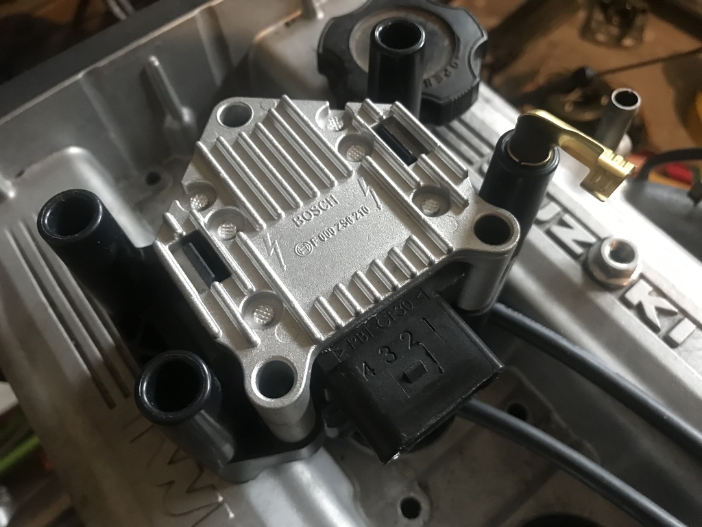
So here's a pic of the ubiquitous Bosch 'smart' (meaning ignitors are in-built) wasted-spark coil pack that I'm going to be using initially...
I came up with the idea of mounting this on the engine itself, alongside the original distributor. Looking at the thermostat mounting lug on the head, I schemed up a quiuck bit of CAD :
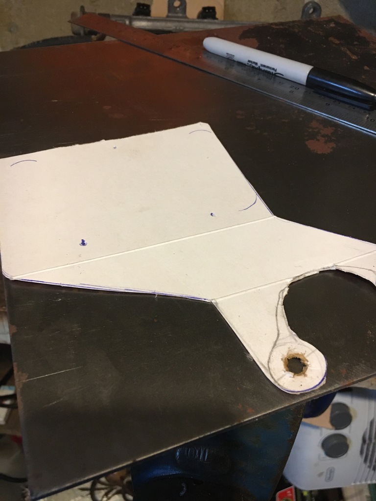
That I could then start wrangling....
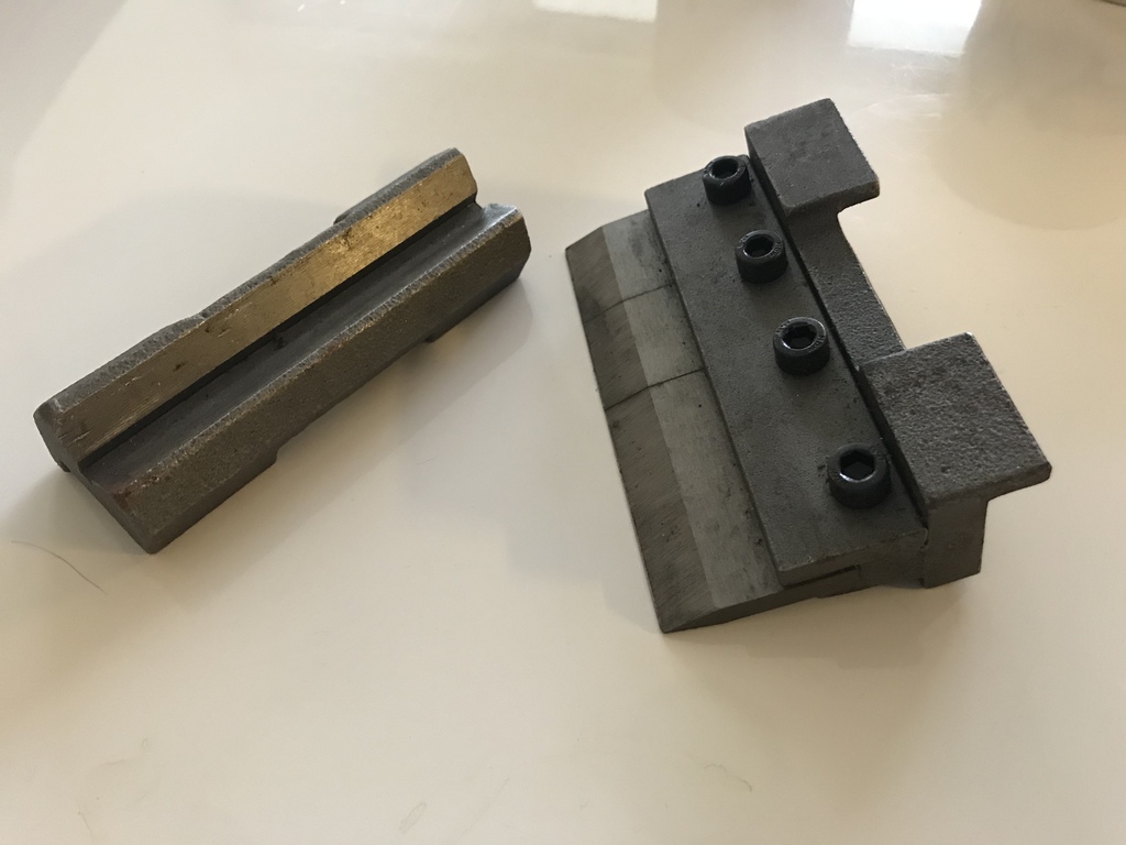
Before getting to use a tool that for me is worth its weight in gold. This is a set from Axminster, and when used in conjuction with service tool No1. (in my case a 6' scaffold pole with hub nut sockets welded to the ends) used here solely for its leverage, can quite quickly bend 3mm mild steel in the vice
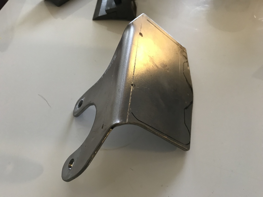
producing this:
Which when the standard thermostat housing bolts are replaced with suitable studs and standoffs, allows me to do this...
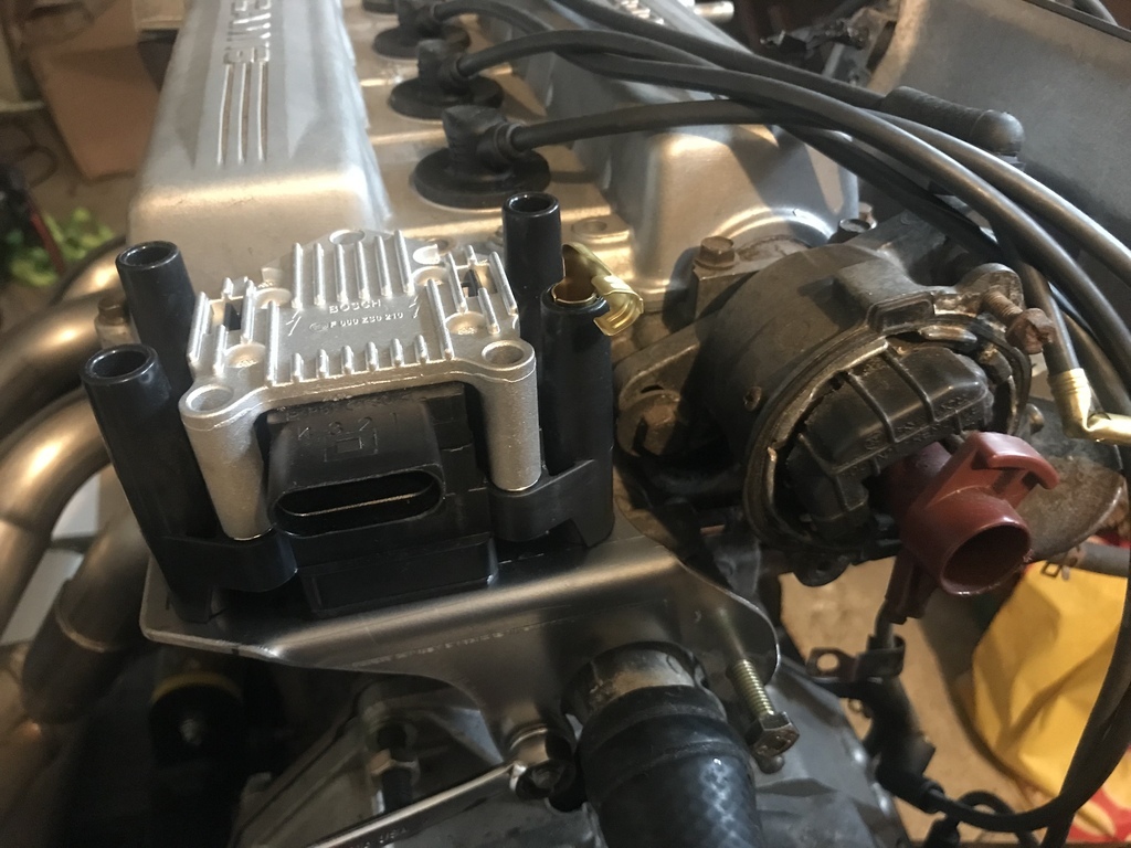
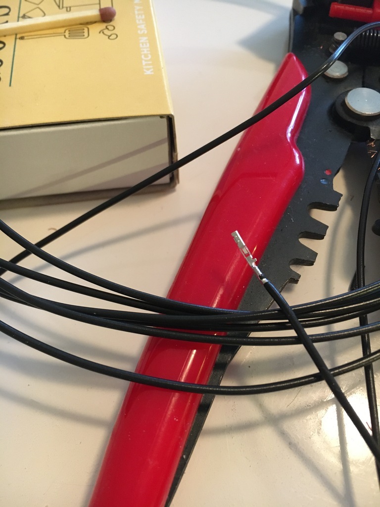
Having misplaced my center-punch and begun to get a little frustrated, I've started to turn my attention to a little wire crimping, 'little' being the appropriate word as you can see from the pic below, and more of which in the next update.....(and maybe a little more zorst action too.....)
Thanks for stopping by as ever...
|
| |
Last Edit: Jan 1, 2022 12:12:40 GMT by 16grit
|
|
16grit
Part of things
 
Posts: 216
|
|
Jan 10, 2022 18:33:47 GMT
|
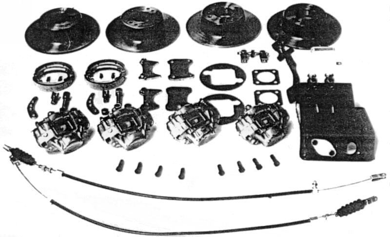
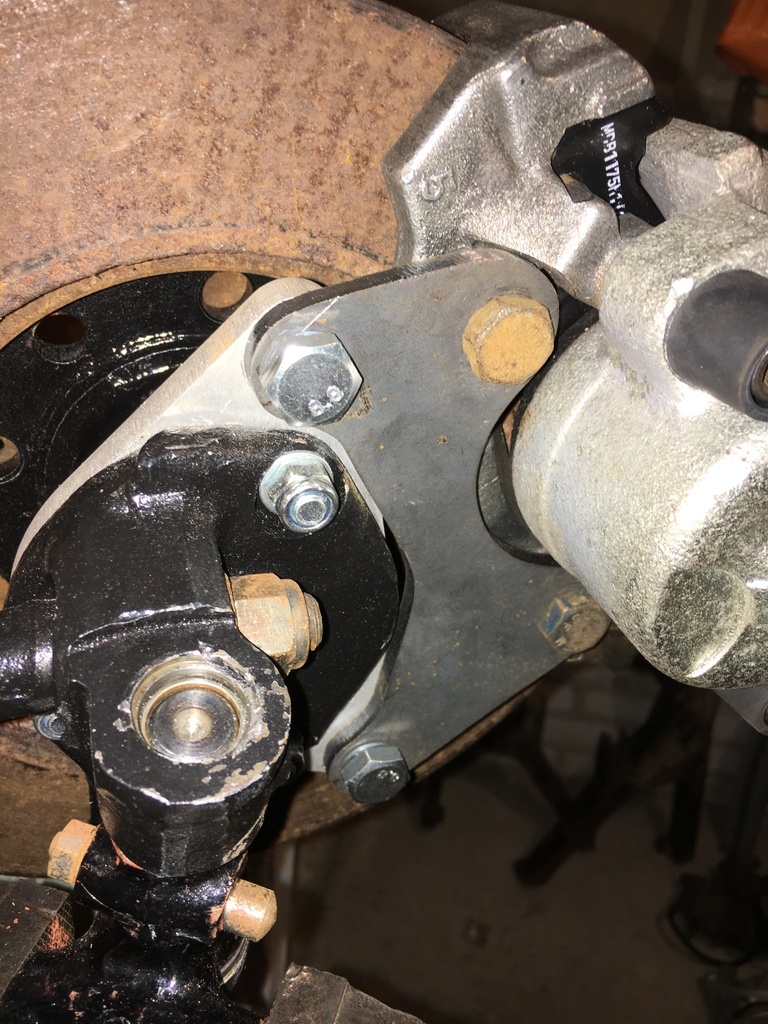
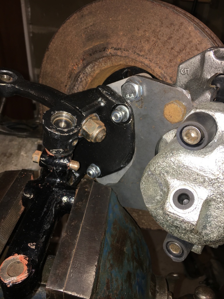
This update is a look at my front brake setup as it is coming together. But why now? Where's the exhaust?! And what about the wiring and ecu? Well I'd like to get my new coil mount and a few other bits zinc plated before the dreaded surface rust starts spreading across them like incredible fungus, and with that in mind ..... my attention turned to the front brake caliper brackets you saw in the pic above, which were going to need some spacers sizing up, before being welded onto the brackets and then the brackets joining the other bits in the 'to be plated' pile... 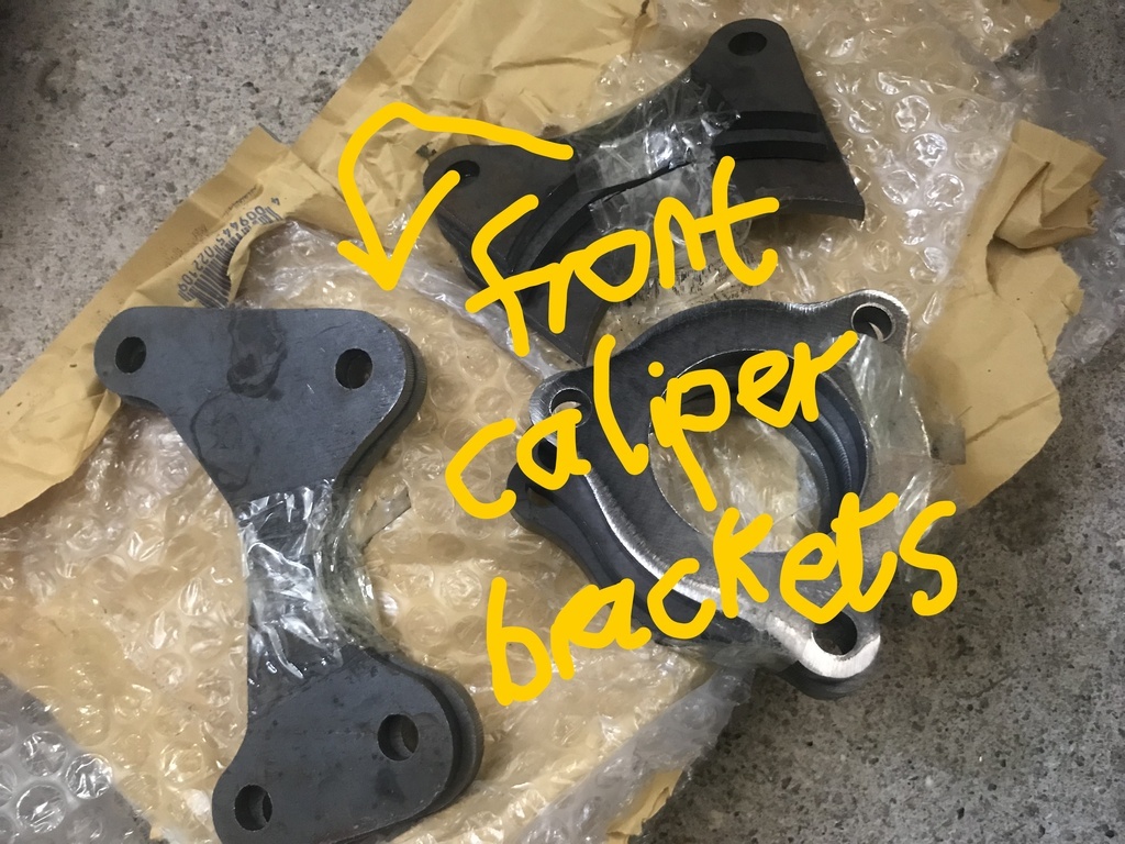 So why is any of this even necessary? Those pictures of the car you posted at the beginning of the thread showed it sat on its wheels, didn't it have brakes? Well yes and no. The front end of the car was pretty much complete - even if this meant that most of the Hillman Imp-derived suspension parts were either riddled with stress cracks, mismatched parts that had been thrown together or simply to rusty to use - the front shocks being a good example of that. Back in the late 70s / early 80s Davrian had developed their own four wheel 10.2" disc and caliper kit, with complete with motorcycle brake shoes operating internally on the disc bells for the handbrake, an idea that has been copied used by lots of people since: Top of the range options here were Girling AR alloy calipers, repops of which have been made available today for the historic rally crowd at wallet-cleansing cost... A look under the front arches of my car when I got it revealed no such period all-alloy braking nirvana, but instead what met my eye was...Some heavy cast iron calipers wrapped around some reassuringly large (260mm) vented discs. From the marks on the calipers (they had 'FORD' cast into them) I deduced that they were Ford calipers... Escort RS Turbo S2 if you want to sound flash, plain old Sierra front if you don't.....
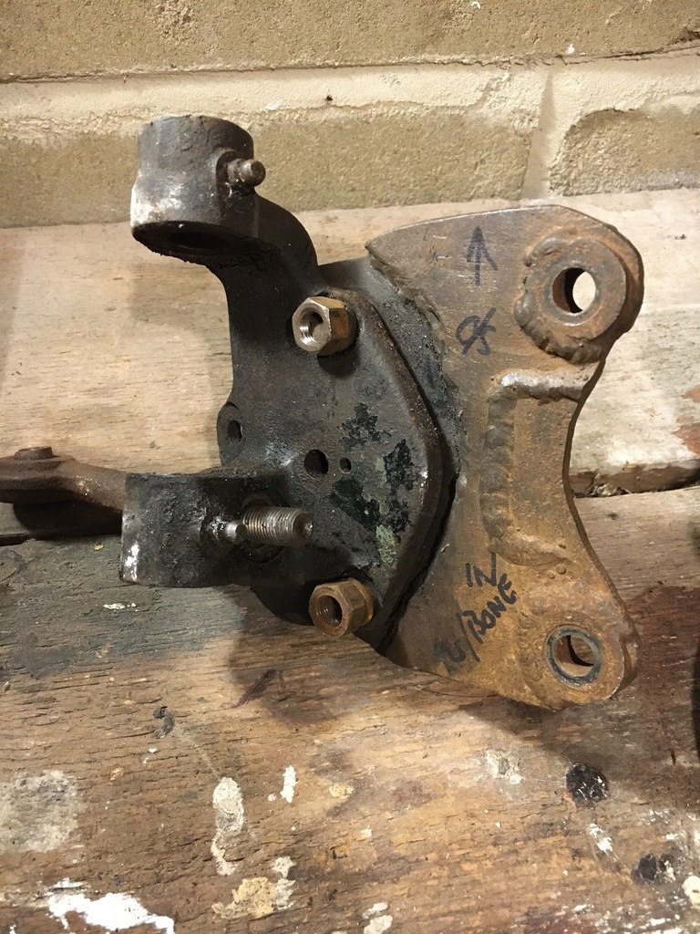
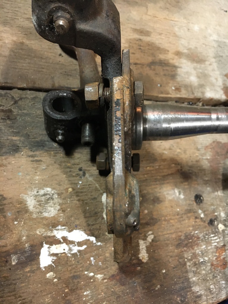
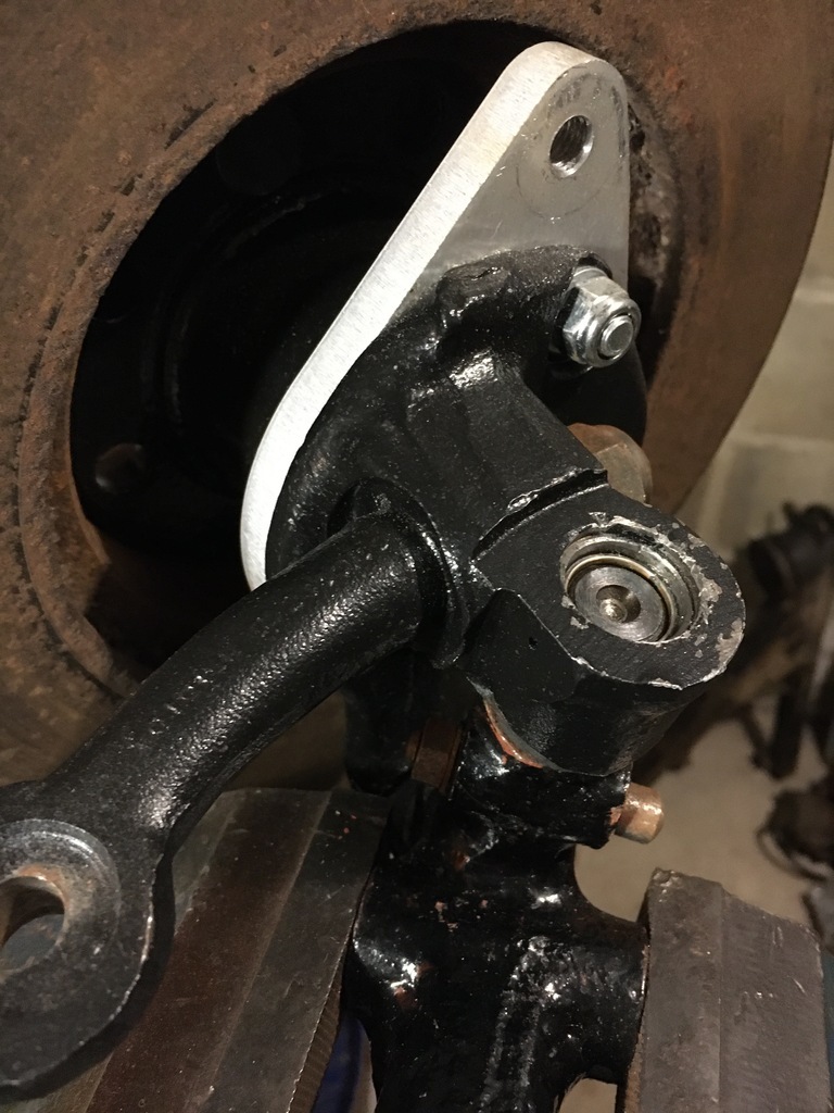
Now these calipers were attached to the Imp stub axles using some the brackets shown here..
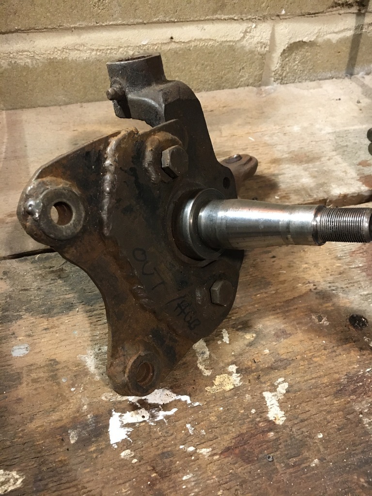 Leaving the execution aside for a moment, there appeared to be a slight design weakness also.....both were bent across the thin section...
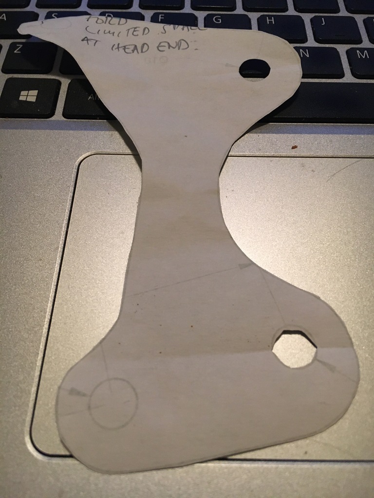
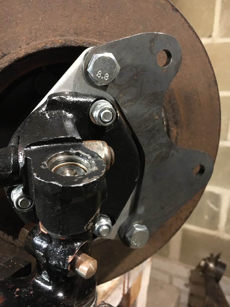
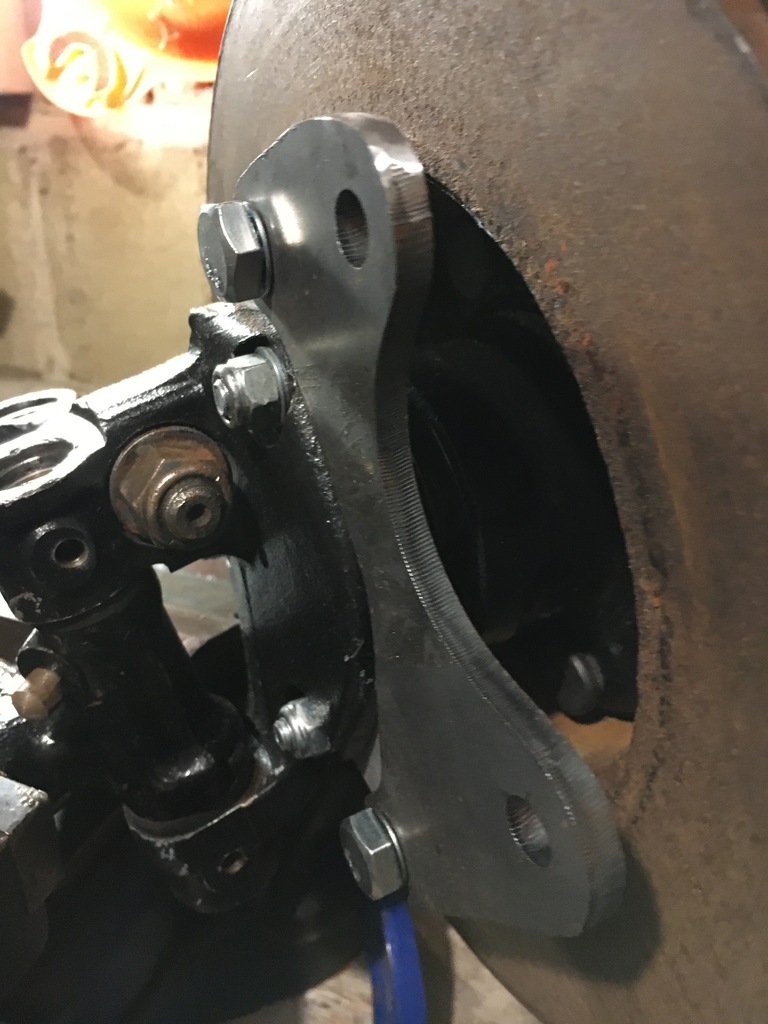
I've toyed with lots of caliper ideas (including RX7 and AP and Girling units), but I've decided at least for the time being, to stick with the cast iron calipers and the 260mm discs - in fact I'm going to try and use them all round the car. For the front, this meant trying to produce some new bracketry... I found these natty alloy brackets to kick me off in the right direction, from one of the Imp disc conversion guys... 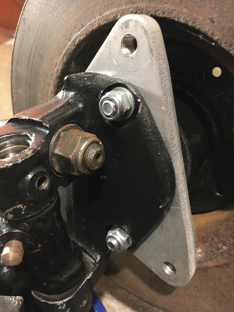 Using the old brackets as a template inspiration, I worked up this Which then got cut and mounted on the other bracket 'cosi' as our EyeTalian cousins might say.... Tiny bit of fettling with my favourite Chinese finger file....
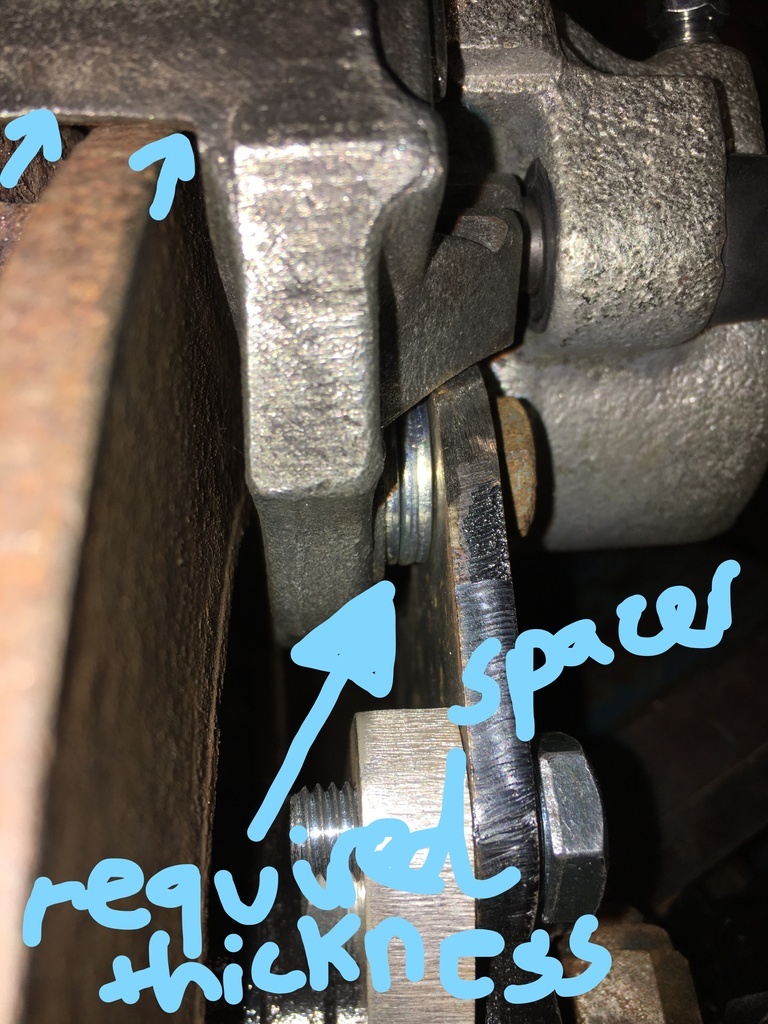
And then presto, refurb caliper and some Mintex pads (which buyer's remorse is already telling me will be overkill on the front).... I then trialled and mostly errored with washers until the disc placed in the centre of the caliper - giving me the dimensions of the spacer that I'm going to have turned to finalise the caliper mounts. I am going to change the hub bearings first though - and although this sounds simple I have a feeling that there might be some mighty Fordiness in the hubs too - once new bearings are in I'll double check the spacer thichness I need...
In the meantime, thanks for checking in ....
|
| |
Last Edit: Jan 10, 2022 18:43:09 GMT by 16grit
|
|
|
|









 we get ....