|
|
|
Jan 11, 2022 16:29:15 GMT
|
|
Nice to see another Davrian being brought back to life!!
Use to hang around with a load of the Modsports gang in the late 70s/80s.
Had a road going Bevan Imp powered MK8 myself.
Must still be a few laying around in people's garages waiting to be recomissioned !!
Good luck in your next stages !!
|
| |
|
|
|
|
16grit
Part of things
 
Posts: 216
|
|
Jan 11, 2022 17:21:02 GMT
|
Nice to see another Davrian being brought back to life!! Use to hang around with a load of the Modsports gang in the late 70s/80s. Had a road going Bevan Imp powered MK8 myself. Must still be a few laying around in people's garages waiting to be recomissioned !! Good luck in your next stages !!
Thanks for the interest, appreciated. Amazing what they achieved in Modsports when the cars were in fact very 'standard' in their own way
As you say, there's got to be a fair few in garages dotted around the place, there's a pitifully small number actually being run! That's a real shame in my
view considering the competition pedigree.
|
| |
|
|
|
|
|
Jan 11, 2022 20:54:12 GMT
|
Nice to see another Davrian being brought back to life!! Use to hang around with a load of the Modsports gang in the late 70s/80s. Had a road going Bevan Imp powered MK8 myself. Must still be a few laying around in people's garages waiting to be recomissioned !! Good luck in your next stages !! Theres at least two... |
| |
Koos
|
|
|
|
|
Jan 11, 2022 22:43:31 GMT
|
|
Somehow I had missed this thread. Now, after one strong coffee I have read it through. Its a cracker and some of the info and mods you have posted are relevant to my Imp project. I'll be having to chop the centre section out of my rear suspension cross member and raise the tunnel under the rear seat area by about 60mm to allow for my Subaru Leone transmission to sit in there. It interesting to see how Davrian ended up going their own way in that area to allow for other boxes to fit.
Please keep the posts coming. Its an interesting and entertaining thread!
|
| |
|
|
16grit
Part of things
 
Posts: 216
|
|
|
|
Somehow I had missed this thread. Now, after one strong coffee I have read it through. Its a cracker and some of the info and mods you have posted are relevant to my Imp project. I'll be having to chop the centre section out of my rear suspension cross member and raise the tunnel under the rear seat area by about 60mm to allow for my Subaru Leone transmission to sit in there. It interesting to see how Davrian ended up going their own way in that area to allow for other boxes to fit. Please keep the posts coming. Its an interesting and entertaining thread!
Great to have you along for the ride. Looking forward to hearing the soft lilt and refined torquey thrum of that Goldflapper motor going into yours...
'Davrian Developments' used to make a pretty big thing out of the torsional rigidity of their all-fibreglass Davrian shells compared to their traditional steel counterparts, and binning the rear cross-member worked on this level as well as the practicality of wider track and bigger boxes from more manufacturers.
I'm not qualified to offer you any advice as you are about to cut the rear floor out of your Imp, but I can sign off with some of Adrian Evans' Davrian Developments marketing at its peak-70s finest......
 |
| |
Last Edit: Jan 12, 2022 7:35:02 GMT by 16grit
|
|
16grit
Part of things
 
Posts: 216
|
|
Jan 22, 2022 13:51:10 GMT
|
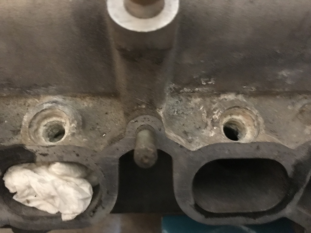
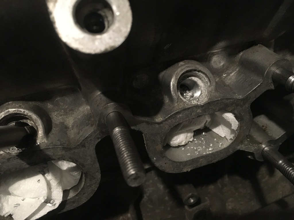
So this one is less of an update and more of a 'backdate'... No... not that kind of backdate, the fashionable 'ooh I'll just put some 70s 'inspired' elephant leather seats trimmed with gecko eyelashes into my '85 911 but hang-on-a-minute-while-I-just-launch-my-new-and-eqally-luck-zur-riant-line-of-bee-spoke-wrist-watches-while-the-sewing-machine-is-cooling-down..NO! Instead, I'm talking about the kind of recurring revision that the 'triers' like me (rather than the achievers) go all-in for on projects like the one I am attempting here...where you finally get something done....months pass by.with plenty of thinking time...and then you do it again, but different....then you do something....months pass by with plenty of thin... Now, it just so happens that the little Suzuki 1300 'TC' was designed with injector bosses in the head casting, reet up close to the valves, after the throttle plenum. The early engines (designed back in 1985) used a traditional (but electronic) distributor for the ignition. There was an ecu too, powering the (reasonably large, low impendence) injectors sat in those very same injector bosses. For those yearning for the solace of simpler times and the induction roar of a pair of sidedraft Carb-burritos, all you need do is simply bung-up the said holes in the head, sling on a suitable manifold and suddenly with the addition of a little bit of Bologna's best your highly strung mamoiselle butterfly is all ready to reach some kind of Eye-watering Eye-talian sonic Nirvana.. All very well and good in theory of course, but ...surprising as it may seem, 1985 what not just yesterday and your injector orifices are more than likely to look like this...
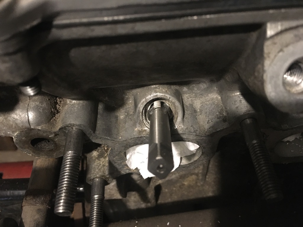
After a little bit of cleaning, some measuring suggested I wasn't a million miles away from being able to tap the injector bosses out to M12,
Which after a few twists of the fingers gave me this..
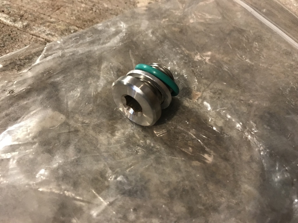
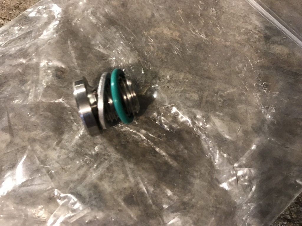
Now I had some freshly cut threads I had to find something to "fill the void" that even a fried egg sandwich wasn't capable of achieving here...so, after copious eebayerizing, with all the professional forethought of a Simon Cowell conjuring up another boy-band I put this little combo together, which as I'm sure you won't fail to notice, bears witness to my new-found sense of a responsibility as a petrol burner, 'doing the right thang' and choosing to 'go green' with the new elements of my fuel system, much more than just another symbolic offering to good old Gretta...
and just as pleasingly....
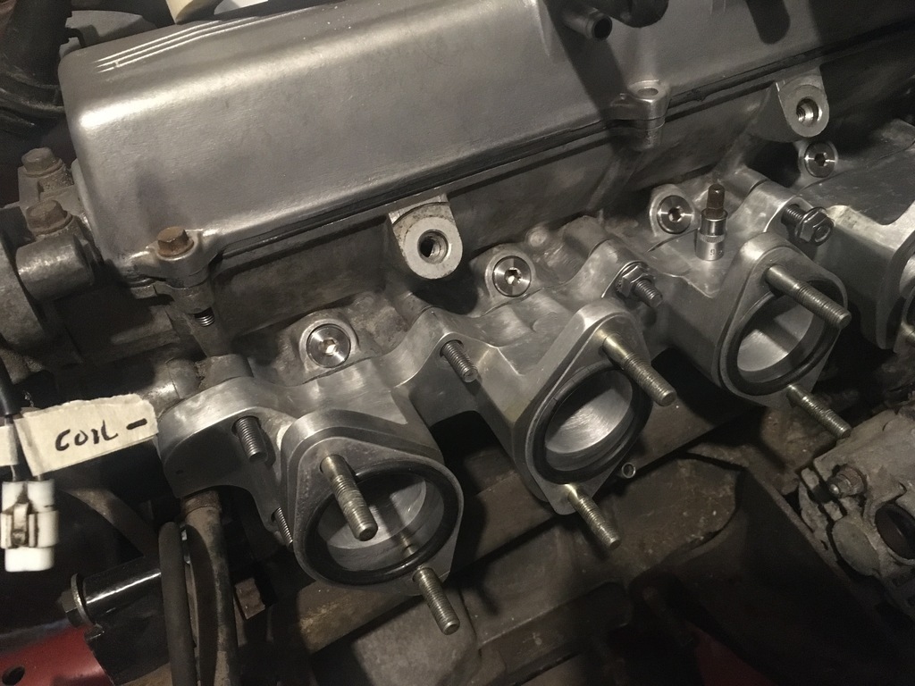
Which when assembled produced this rather fetching vista..
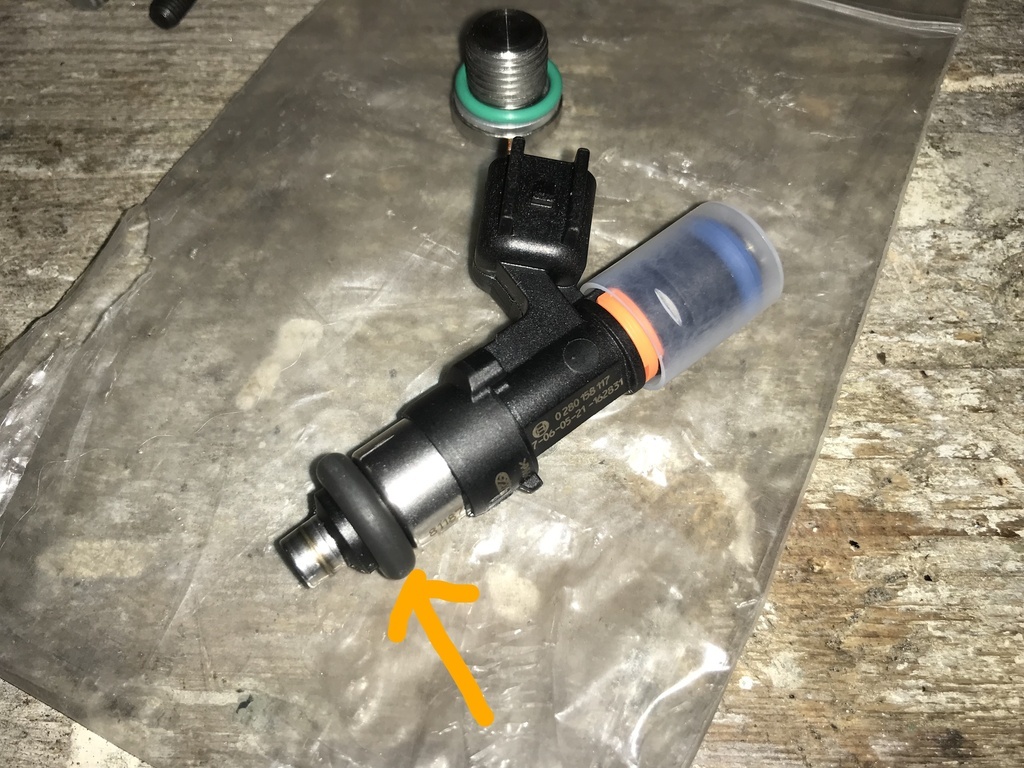
But now I had a job that was actually done, on the good ship niggling doubt, I began to wonder if I wasn't backing myself into a corner (or harbour, or whatever).. One of the original Davrian demonstrators and one of their race cars had run a turbo and if I was going to have the opportunity to do this, in todays ezy-sqeezy-peas kind of way I was goint to need what I had just done to at least also be capable or running injectors...(as god intended) So that's where I am, If I want 'ye olde Eye-talian operatic drama of a pair of Webers I can do that, or should I want the disturbingly ruthless efficiency of some Bosh injectorizers, I can do that too, all it needs is some suitably sized rubbers....
Such as this And this
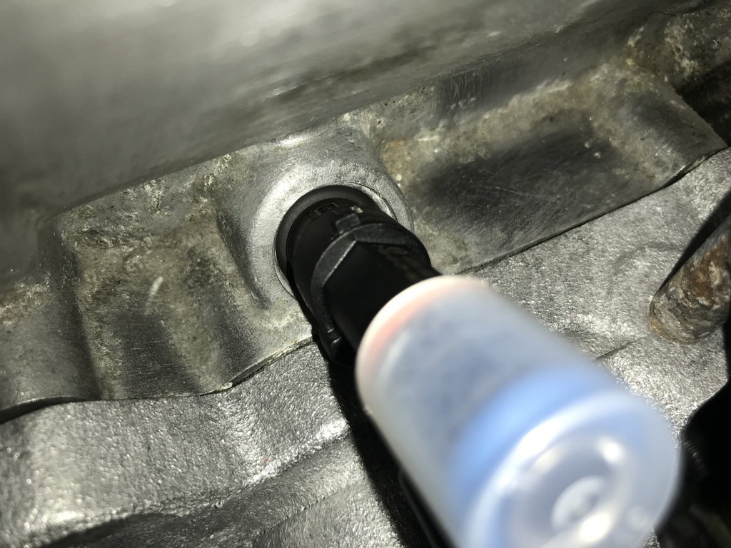 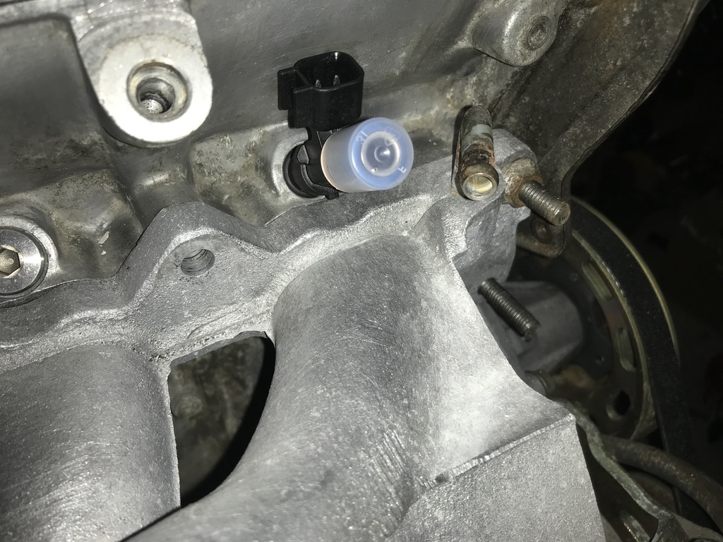 The Italian affair may or may not be over. It might have been one step forward two steps back, but (at least currently) the momentum is deffo with trying to get the car running on injection .....
That's it til next time when I hope to be bringing you more info on the loom I'm putting together to run the injection and finally be able to tidy up a few other loose ends. Thanks for your patience.......
 |
| |
Last Edit: Jan 22, 2022 19:34:42 GMT by 16grit
|
|
16grit
Part of things
 
Posts: 216
|
|
Feb 19, 2022 15:54:10 GMT
|
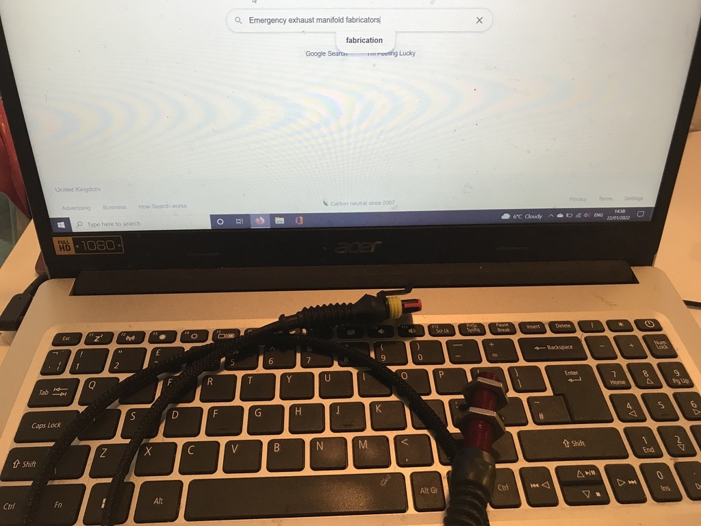
I've been looking at some other bits of my injection system... Like, stripping down the fuel rail.. Remembered I had this bit of stock under the bench for that all importance extra-boost 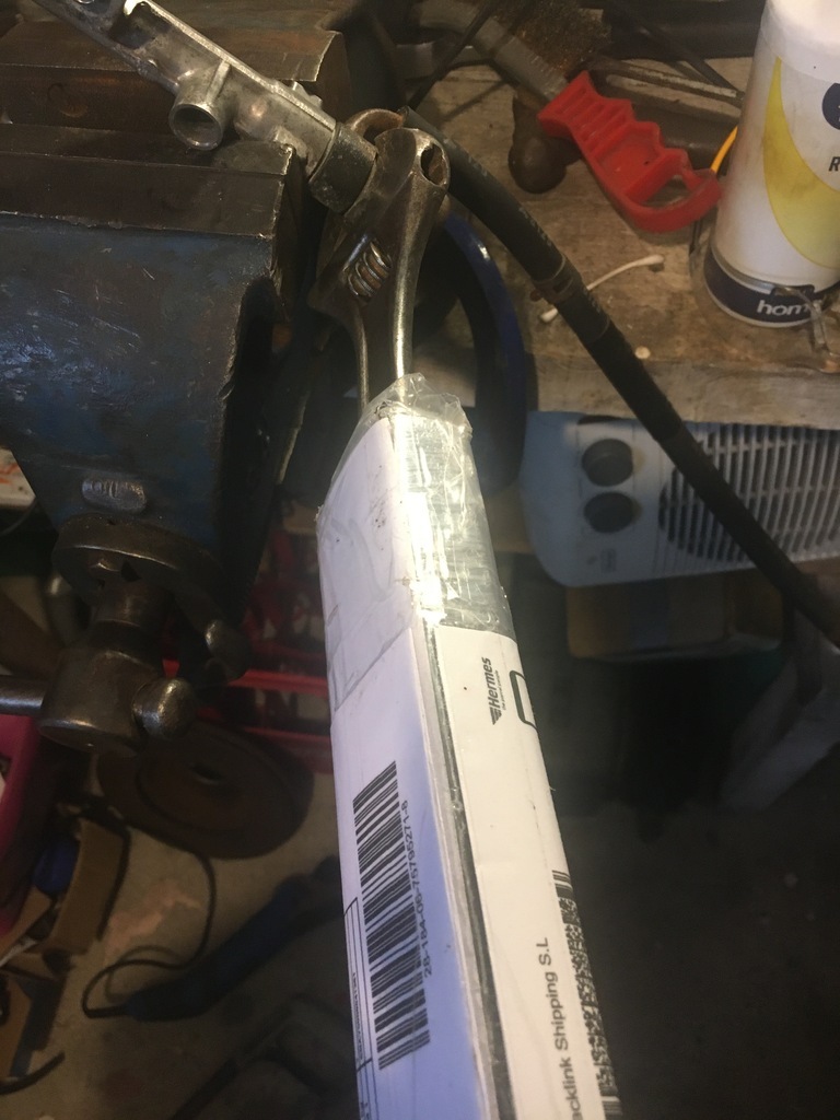 Which meant I could make a start on the pressure release side.. 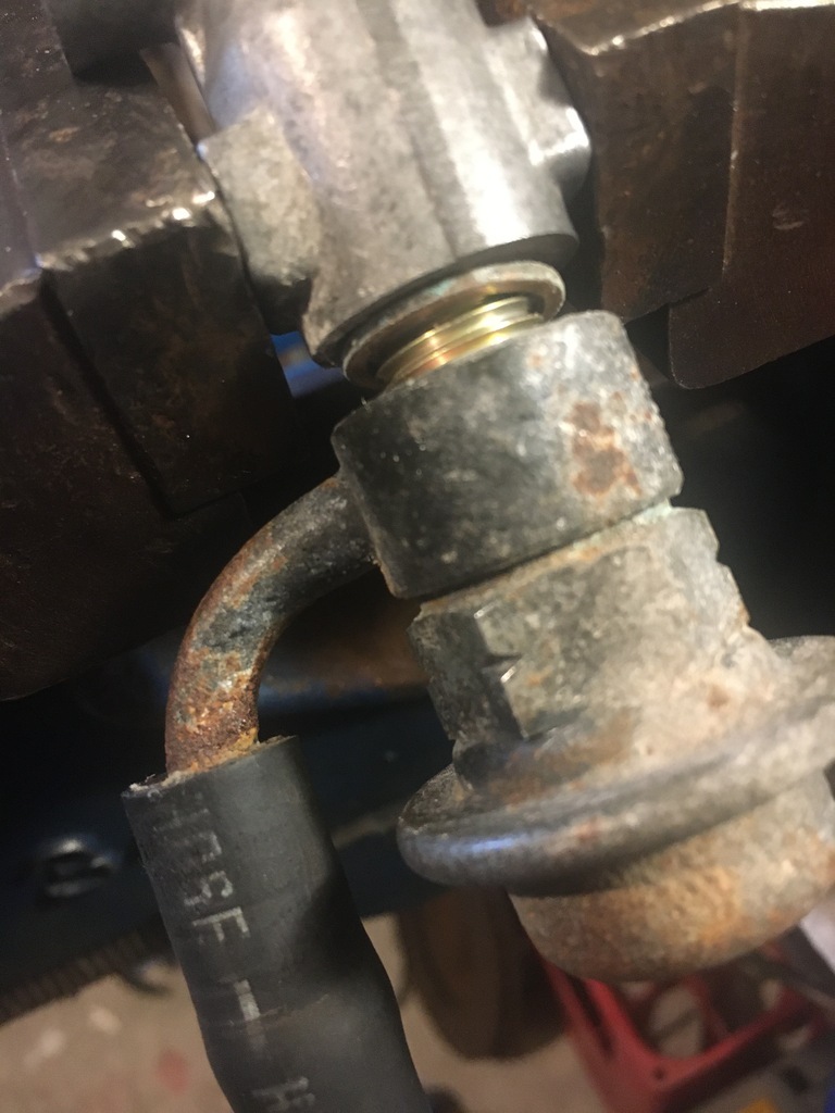 With the rail not having been apart for 36 years I thought I should do the right thing and buy the correct torx.. 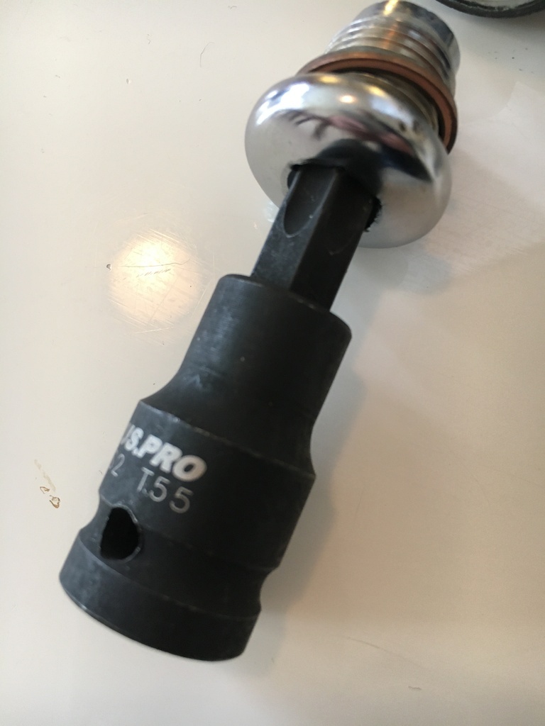 In the end those weren't really any trouble compared to the obstinacy of the last injector... 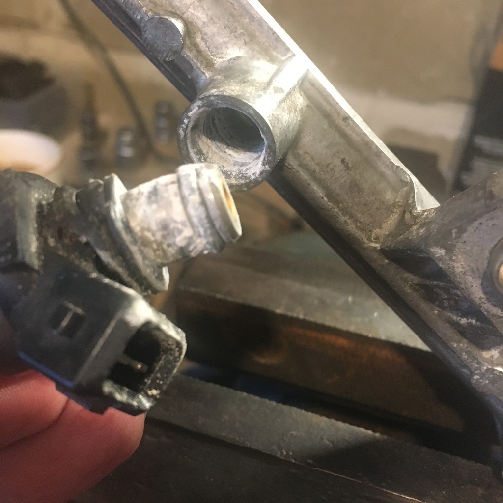 That left just the fuel feed side which would need to be changed after suffering some damage, probably out of the car, when the motor was being moved.. 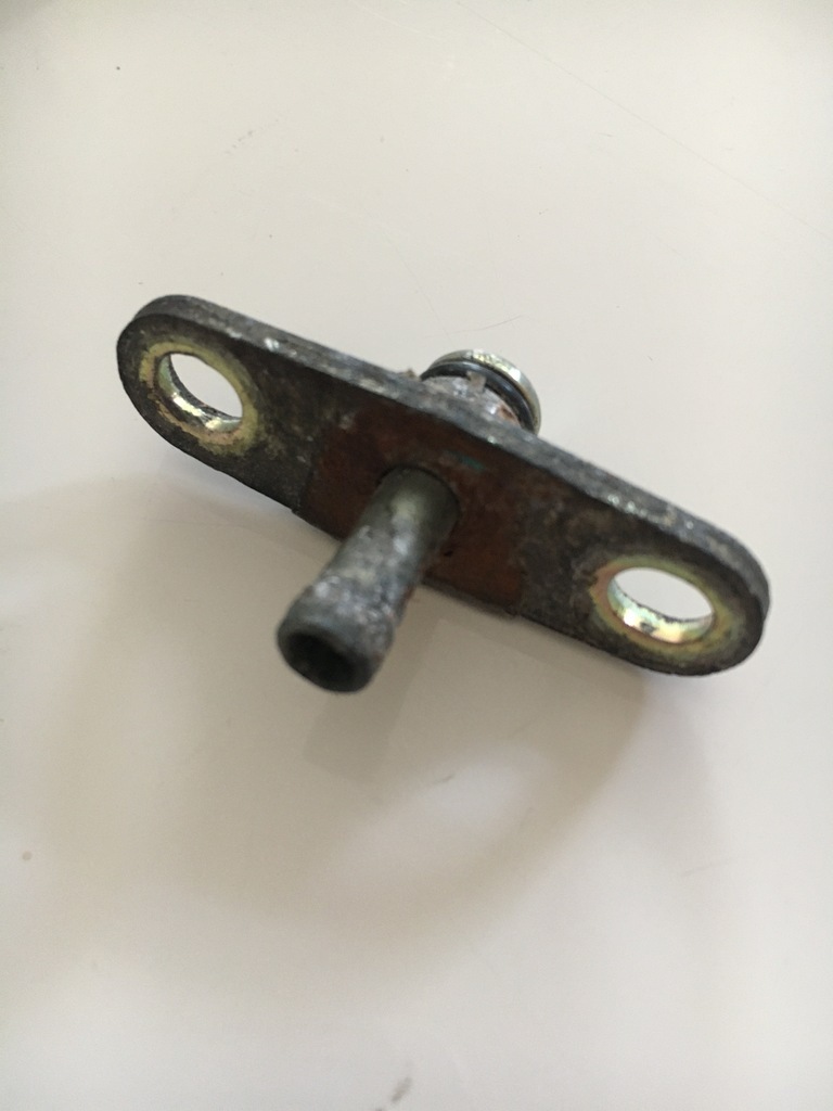 Leaving me with this 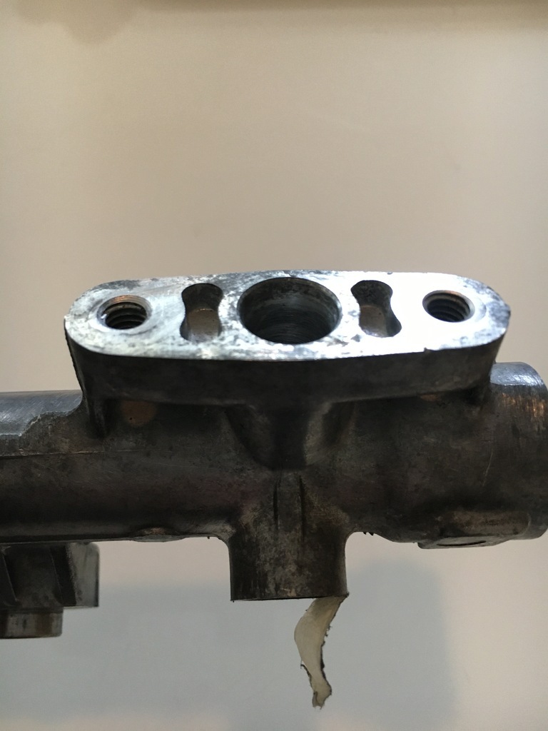 Drained some more of my life-force into ebay and woodjabelieve it.... 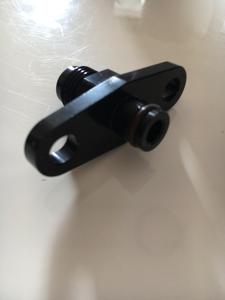 Which was thrown on an ever-expanding pile of tiny pieces that bears no relation to the time expended on sourcing it all, but hopefully will all want to play nicely together sometime in the future... 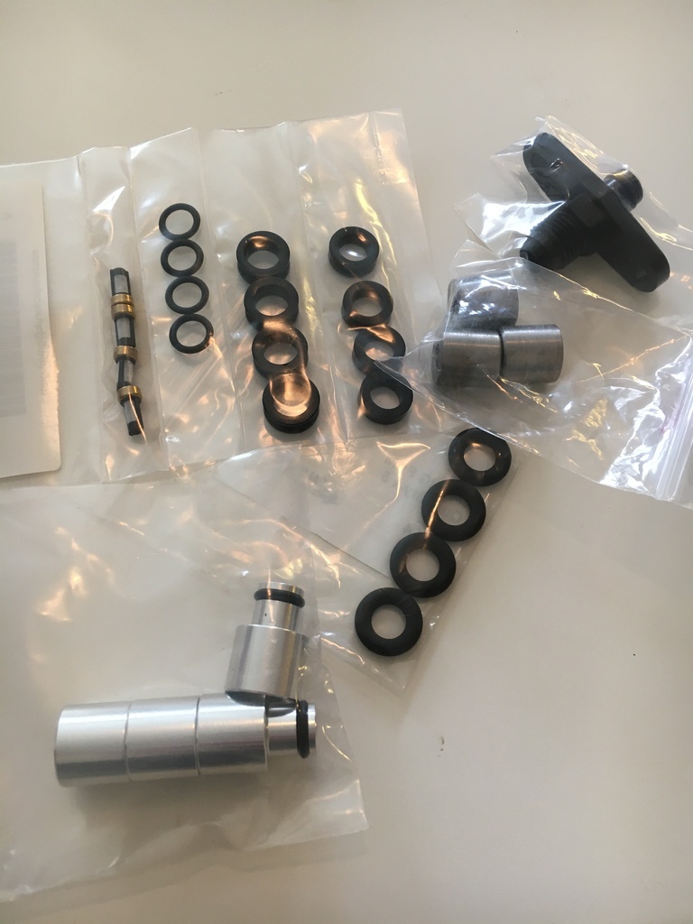 A few of the standoffs I had ordered meant I could progress my coil mount a fraction 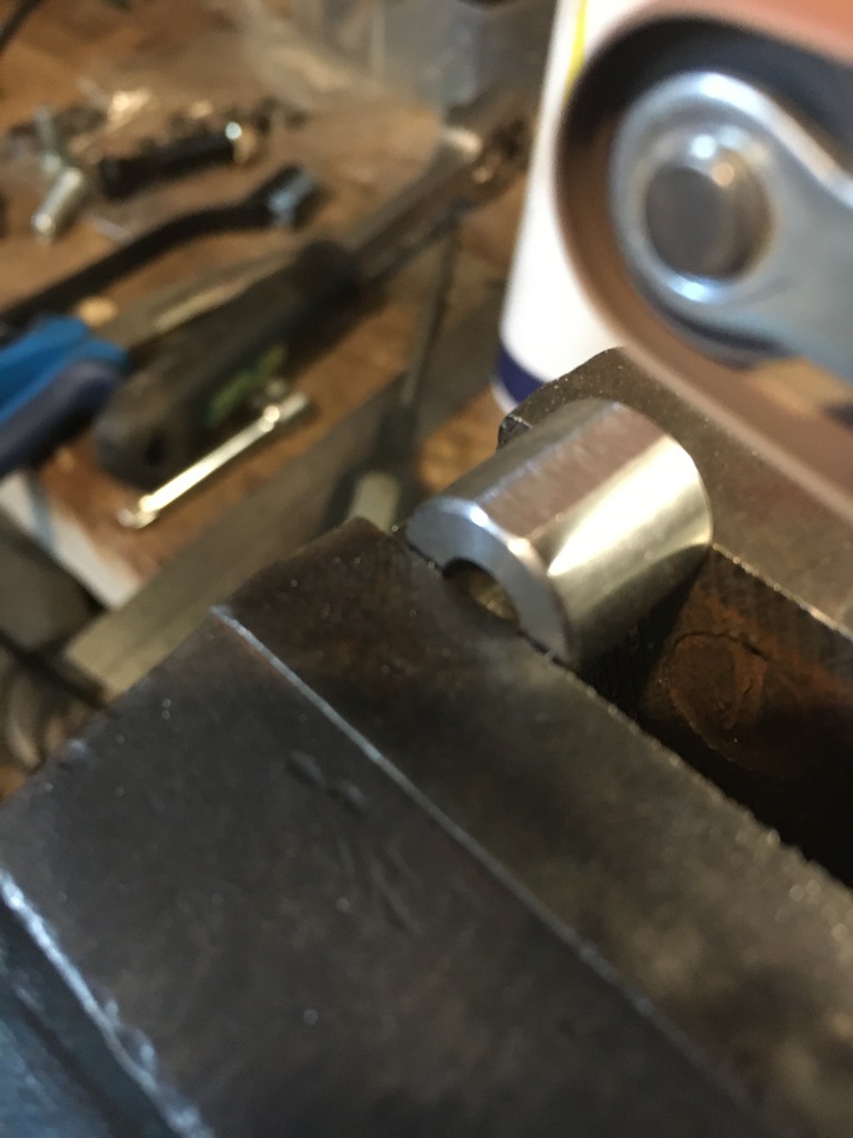 Becoming this.. 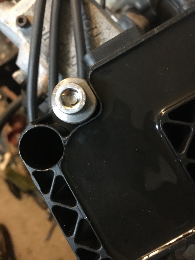 Wide angle view of the same thing minus the coil.. 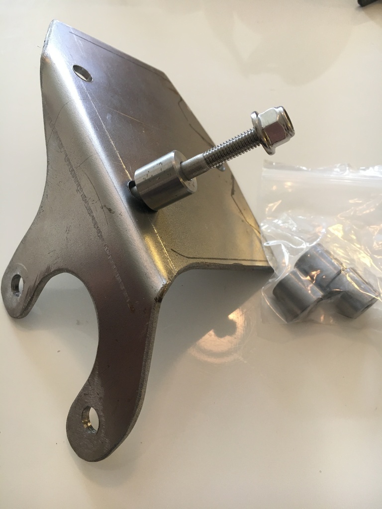 Made up my throttle position sensor ('TPS') cable, and started looking at the ally adapter I'm going to need to fashion to marry this up my (standard) throttle body 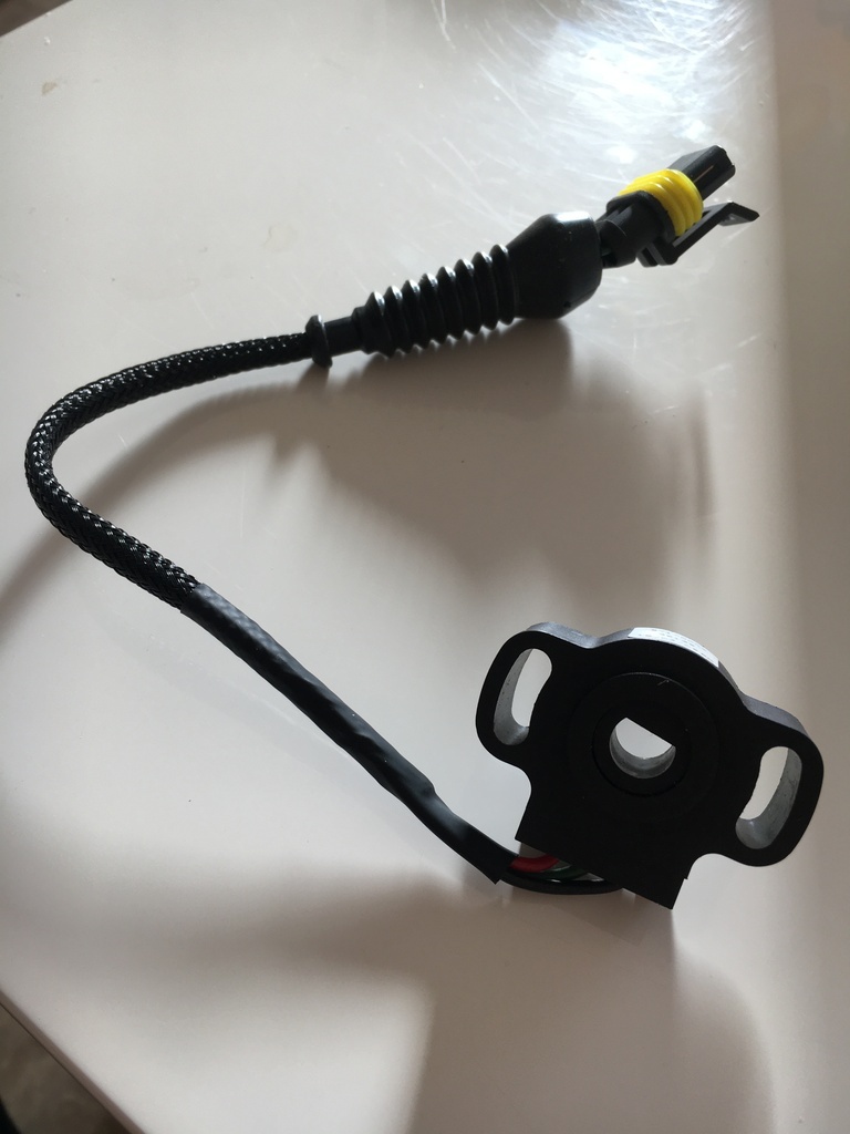 And finally glued my caliper bracket spacers where they are going to live meaning my front hub assemblies are moving forward too.. 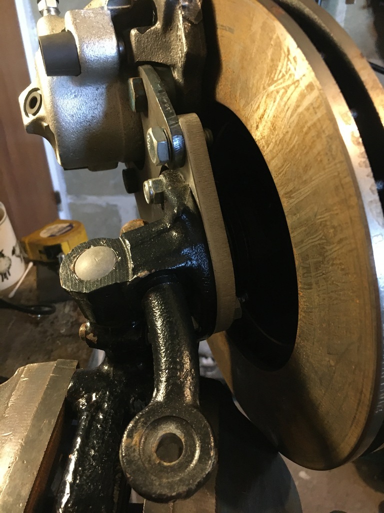 And 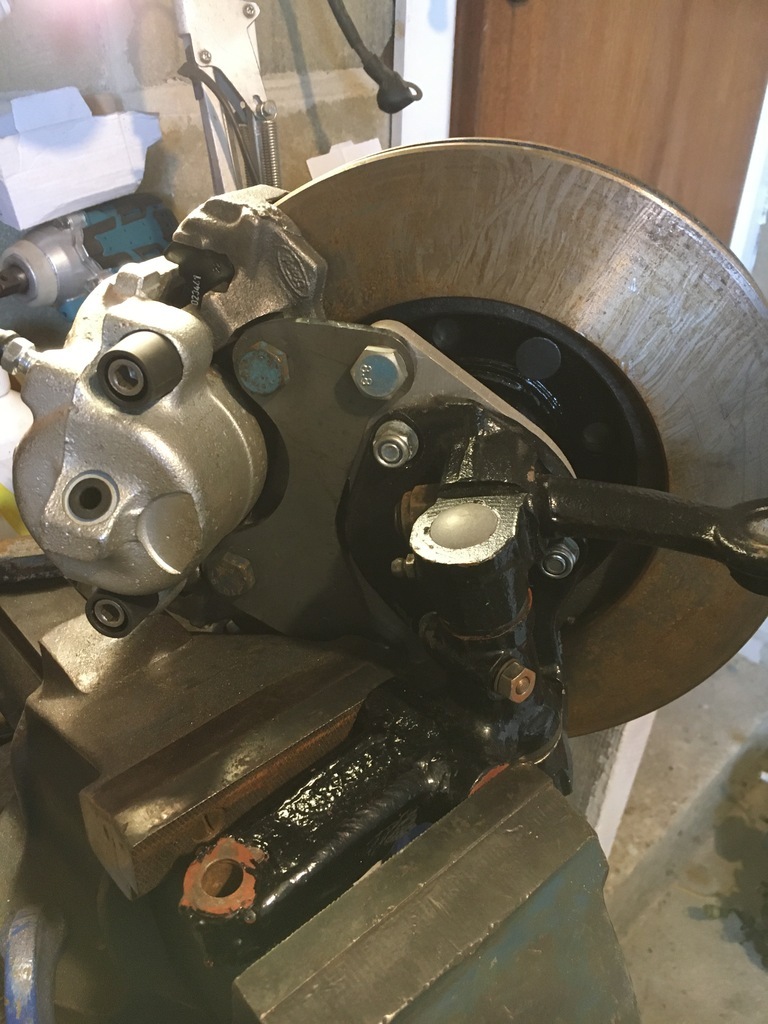 Now with the project moving towards completion at such a blistering pace on so many levels  ..it was obviously time to sit back, take stock, cast an admiring eye of everything I had achieved so far and... and promptly take the rash decision to consider completely changing direction... 
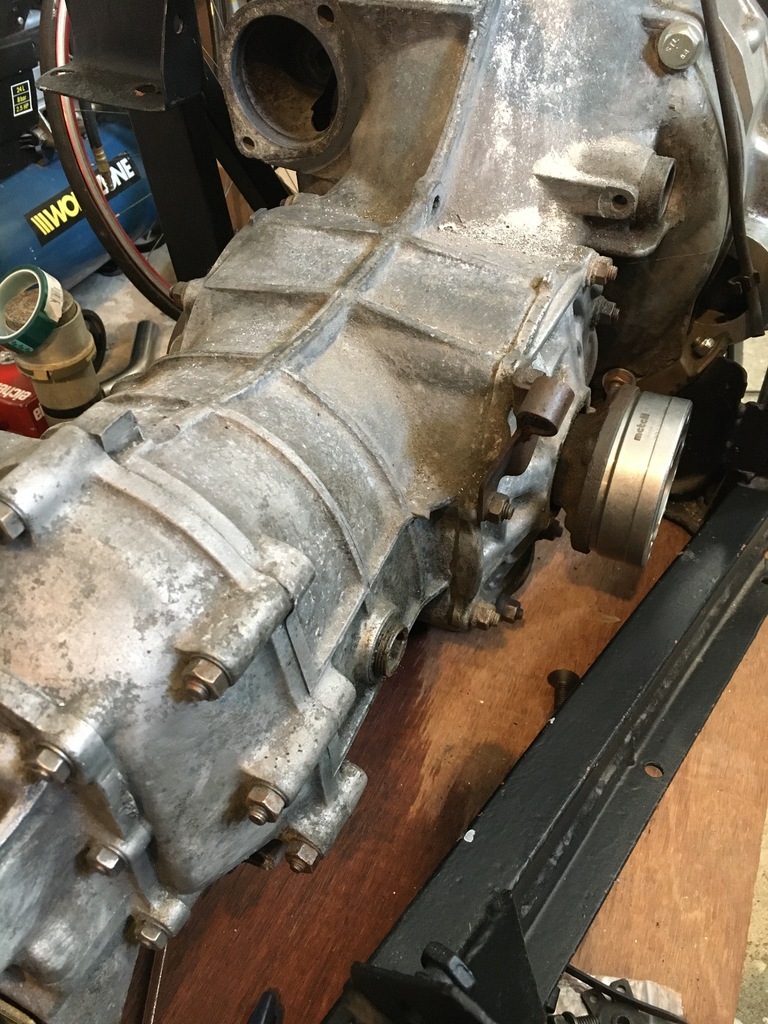
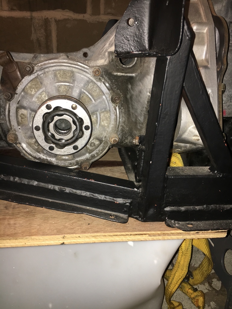
Now as things stand my current (VW-based) gearbox setup looks like this
which through not just a little bit of time, effort and money has been persuaded into some kind of bizarre Ford-sponsored Germano-Japanese mating operation pictured all 'discovery channel' style right here:
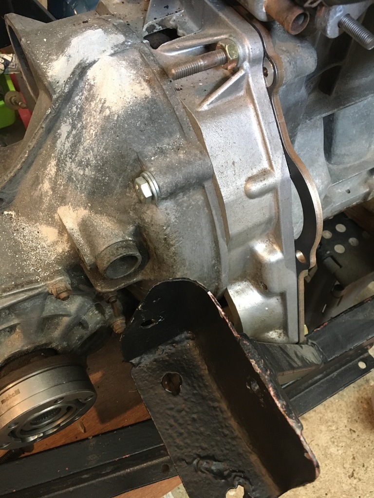
Now, this particular gearbox was only ever intended to be a 'placeholder', waiting patiently for the day its amazingly badly spaced ratios and made-of-glass internals were jettisoned for a suitably bastardized Anglicized version of the little German Beetle-Box in the form of a choose-any-ratio-you-want-but-don't-ever-think-about-putting-too-much-torque-through-my-sensitive-parts HEWLAND version. Only problem being, finding Hewland bits these days seems VERY DIFFICULT INDEED, almost at any price. Maybe its all those retro-single-seater-lovers snapping them up but even if you can find the right combination of parts, the thought of spending a heap of cash on a box that really isnt that strong by contemporary standards anyway was pushing me onto the horns of a dilemma. Cos the scene tax with the Hewland buys you historic rallying legitimacy dontchaknow... BUT venturing away from the Hewland orthodoxy means binning that as a possibility, something I have tried hard to stick with in other areas, like the brakes for example.
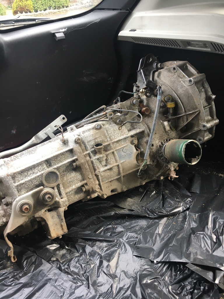
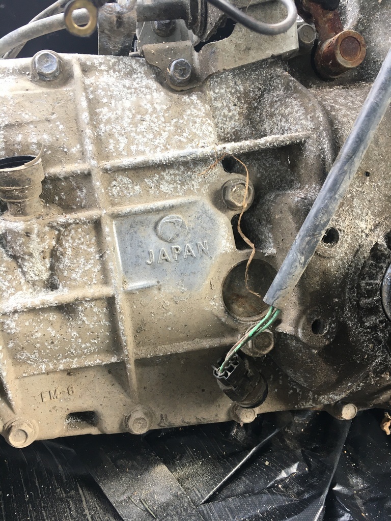
So that's why this arrived at Gritty Towers today...
Sporting this little mark:
All purely for research purposes of course.......
thanks for stopping by...
|
| |
Last Edit: Feb 19, 2022 16:28:59 GMT by 16grit
|
|
|
|
|
Feb 19, 2022 19:09:27 GMT
|
|
If you wanted to keep the Germanic link, try finding an Audi 012 box, Porsche boxster uses the same box with different ratios and rod-actuation I believe.
Could that be an option?
P.S. Is that a subaru box you brought in?
|
| |
|
|
16grit
Part of things
 
Posts: 216
|
|
Feb 19, 2022 19:36:53 GMT
|
If you wanted to keep the Germanic link, try finding an Audi 012 box, Porsche boxster uses the same box with different ratios and rod-actuation I believe. Could that be an option? P.S. Is that a subaru box you brought in?
Thanks for the suggestion. I have considered the 01E (? from memory, hope that's right), think it was in the Passats to begin with. I know this is now the go-to box for lots of people who were using Renault UN1s before they became so scarce. I stopped considering it but can't really remember why, maybe weight. I certainly haven't discounted it out of hand, and it may still be an option, I think there are versions where it ran in front of the engine and could be used 'as is'. Yes the box I have is a cheapy Subaru. This one is actually just a 'placeholder' for dimension checking as its a 'dual range' version, which in the end might only supply the centre-diff casing to be cut down and fitted to a better type. The only thing making this a viable possibility is the subarugears reversed cwp which isn't cheap. In its favour there are quite a lot of factory and aftermarket bits still in circulation for them, and there's a good range of ratios available including close ratio sets. In reversed CWP cut down form the Subaru box is 42kg, heavy not a massive penalty over the VW type 1 and massively stronger. When Ive summoned the strength to actually lift the thing as it stands now I can start taking some actual dimensions, the main issues I'm aware of now are the hight of the layshaft as against the output shafts when compared to the VW box, and also the difference in distance from output shaft flange to bellhousing face. These are likely to cause me problems becasue of the specific design of my rear subframe as it sits now. I don't have a great deal of room to manouver if I'm to keep that as it is right now and raising the engine 50mm isnt appealing and may not actually be practically possible bearing in mind how close the cam cover is already going to sit against the rear 'boot' top...
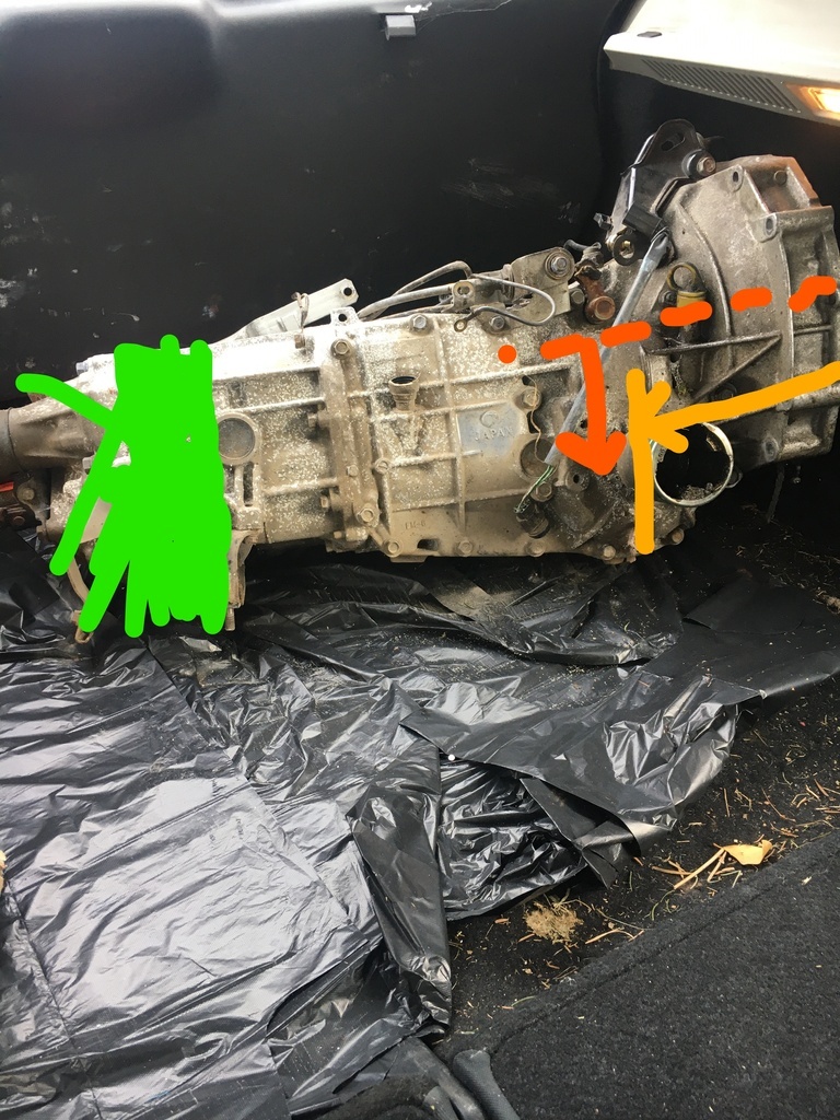
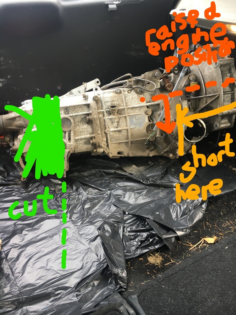
Differences in dimensions fall into this critical bit of space:
I'm going to get the Subaru box cleaned up and then get measuring and see where it takes me, until the thing is actually offered up it is very difficult to judge all the pinch points.
Thanks once again for the reminder on the VW alternative, it may yet be tried!
|
| |
Last Edit: Feb 19, 2022 19:46:31 GMT by 16grit
|
|
16grit
Part of things
 
Posts: 216
|
|
Mar 20, 2022 20:34:37 GMT
|
OK, so where do things stand?
My immediate objective with the car has been to get it to a rolling shell stage. That includes a functioning bias peddle box and working 'period' brakes that fit under 13" wheels, front and back. By implication that also means a checked over, if not rebuilt steering rack, and a rebuild of the rear suspension arms and drive flanges with new bracketry for the brakes which will match those up front. While I've been working through all the re-fabrication etc required for this, I've also tried to satisfy those cravings for more projectry by getting the engine / box married up and aiming to get the Suzuki engine fired up - whatever gearbox it ends up running.
A couple of posts back I grabbed piece of box section from under the bench:
When I went to put this back it dawned on me what I had bought his for. The car has been modified to run a lowered steering rack, presumably with the intention of trying to dial out as much bump steer as possible, even while running quite high. I had already fabbed up the lowering mounts for the rear, but as found, the car used some neat piles of washers to lower the four attachment points on the front wishbone mounting bolts:
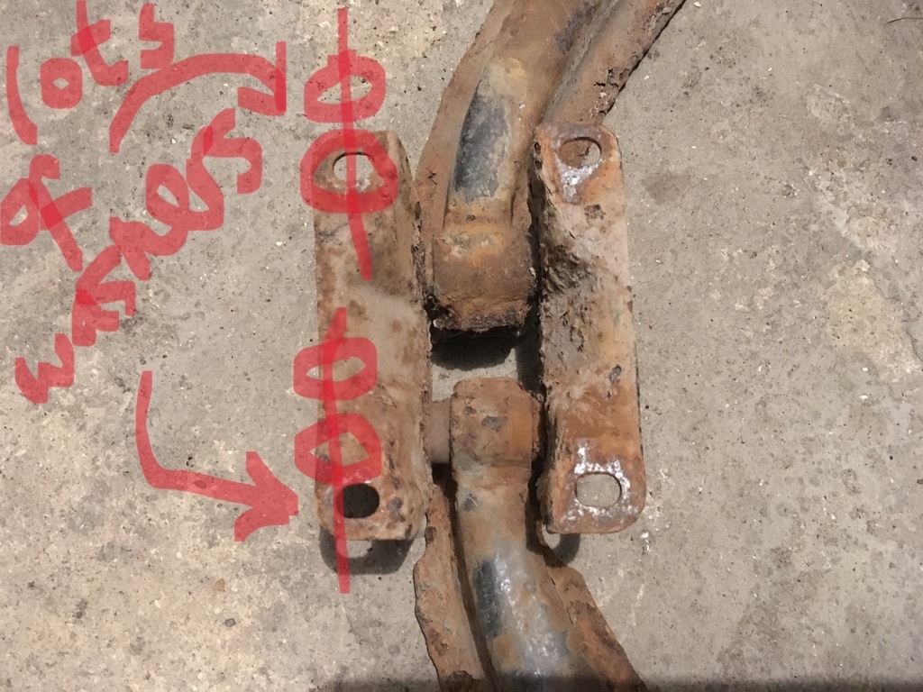
This drops the front pivot points of the front suspension arms to match the rear, and this is how it might look if it were mounted on an Imp, which is where the arms originally came from:
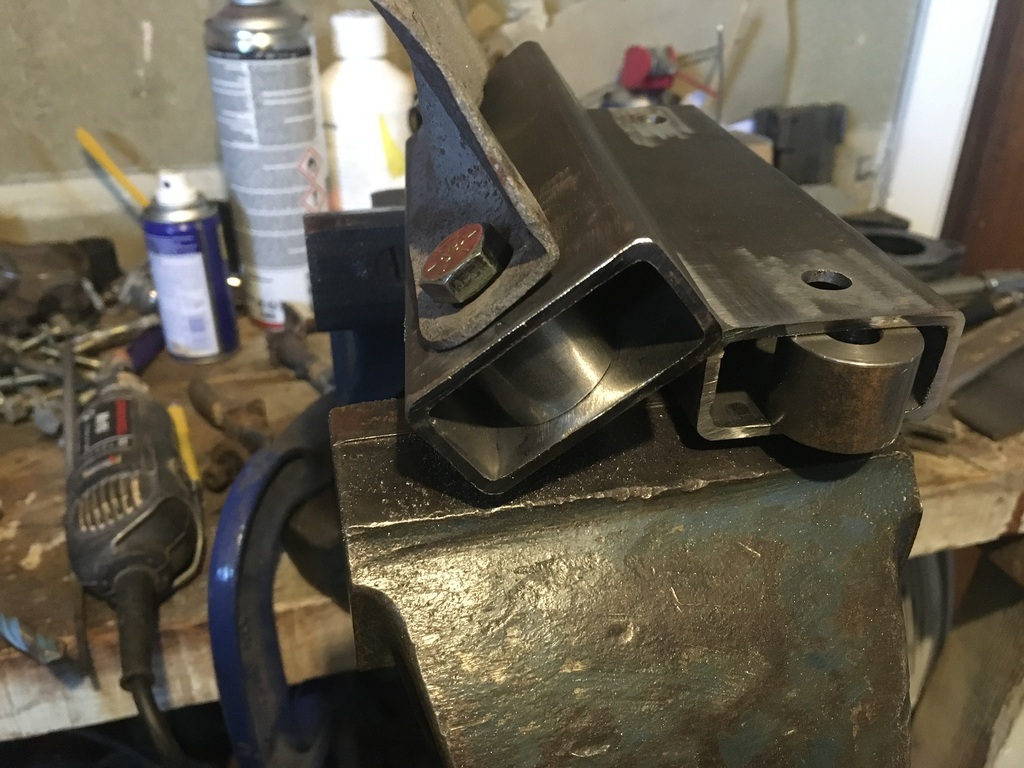
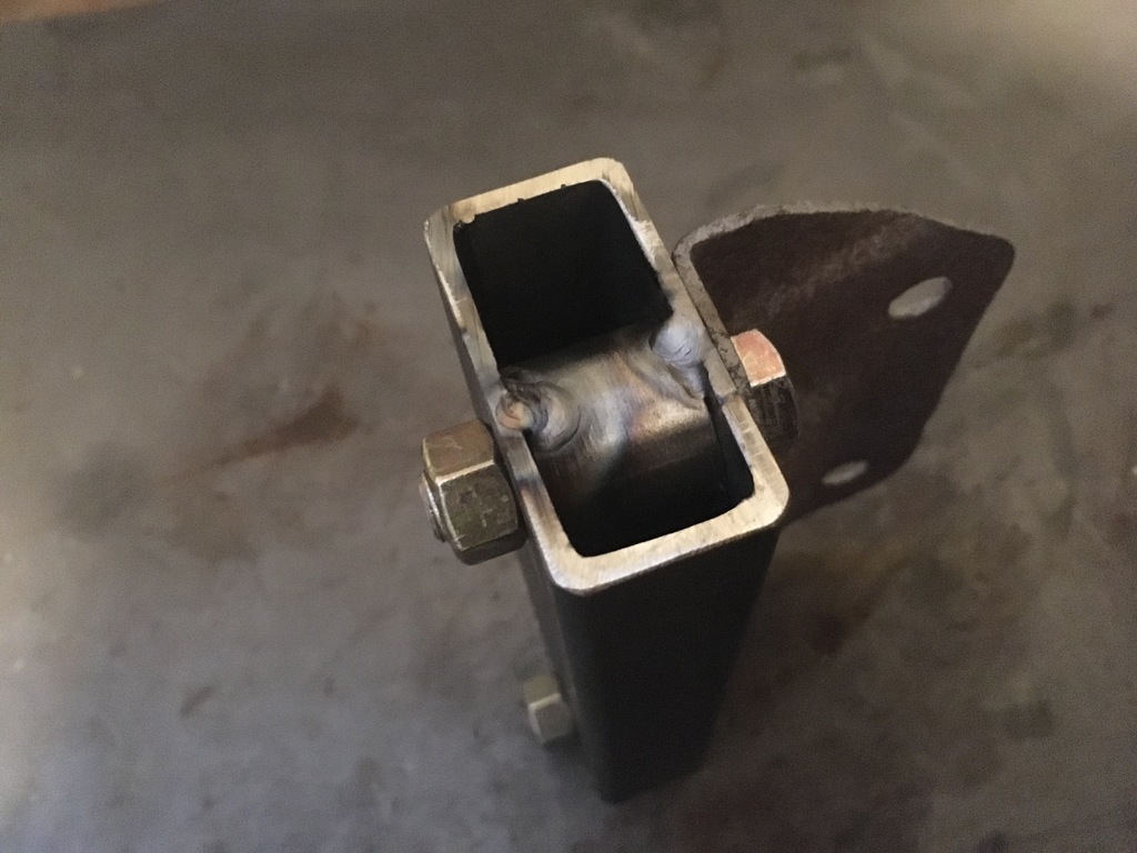
Using washers means that there is some kind of infiinite adjusability in the wishbone pivot location, but having lost the piles of washers carefully considered my options, the sensible thing seemed to be to make up a pair of box section stand-offs, and that's what I set about today. Once these are plated, the front end will be ready to piece together, leaving only a mis-shapen steering wheel and brake line fiddling to deal with...kindof....
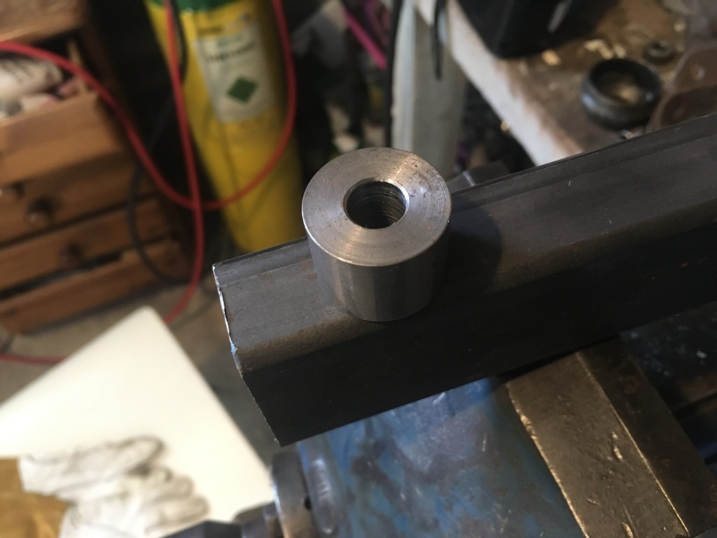
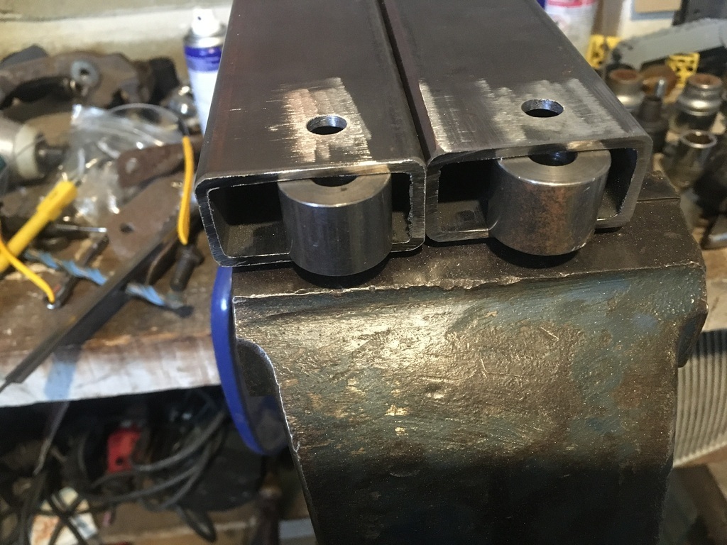
As I've mentioned before, I don't have a working lathe, so I buy ready machined spacers from ebay and buy box section with an internal dimension that provides a nice snug fit for my spacers. It's cheap and easy to do. I bought four spacers like this:
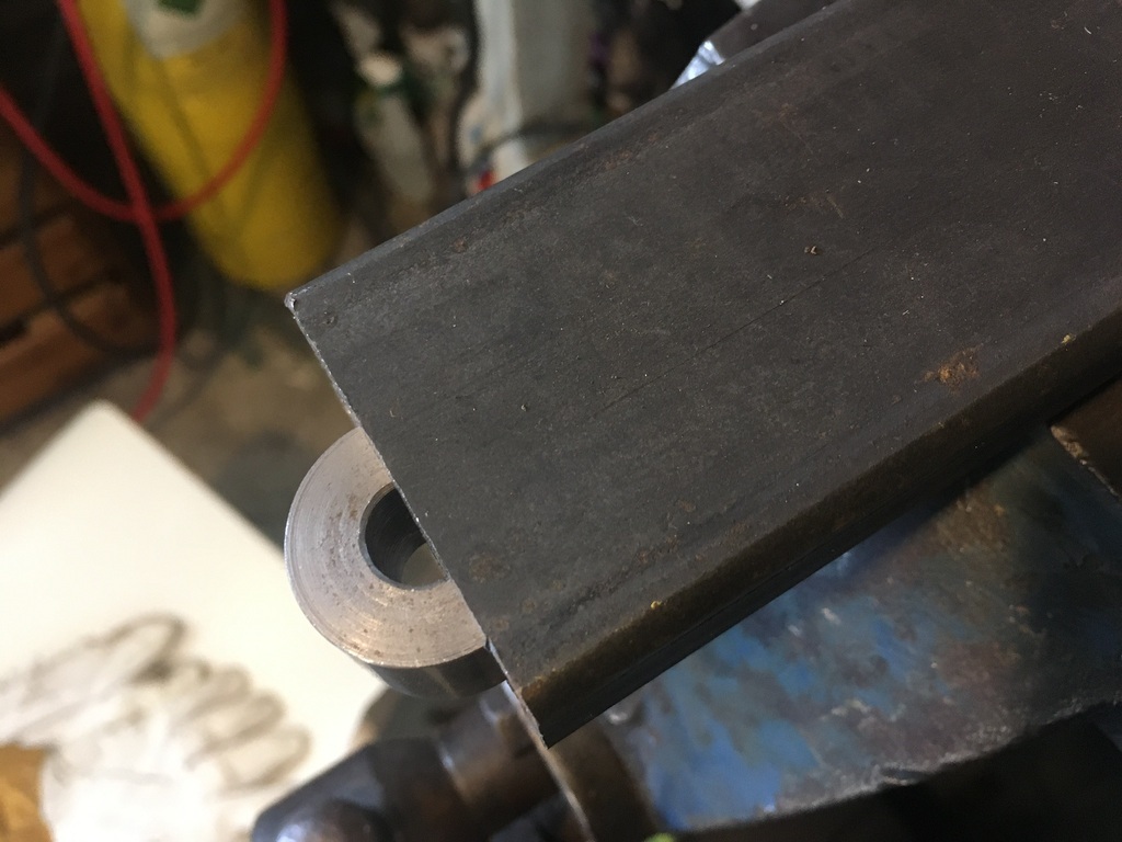
With an absolute minimum of fettling, these would slide into the box section like this:
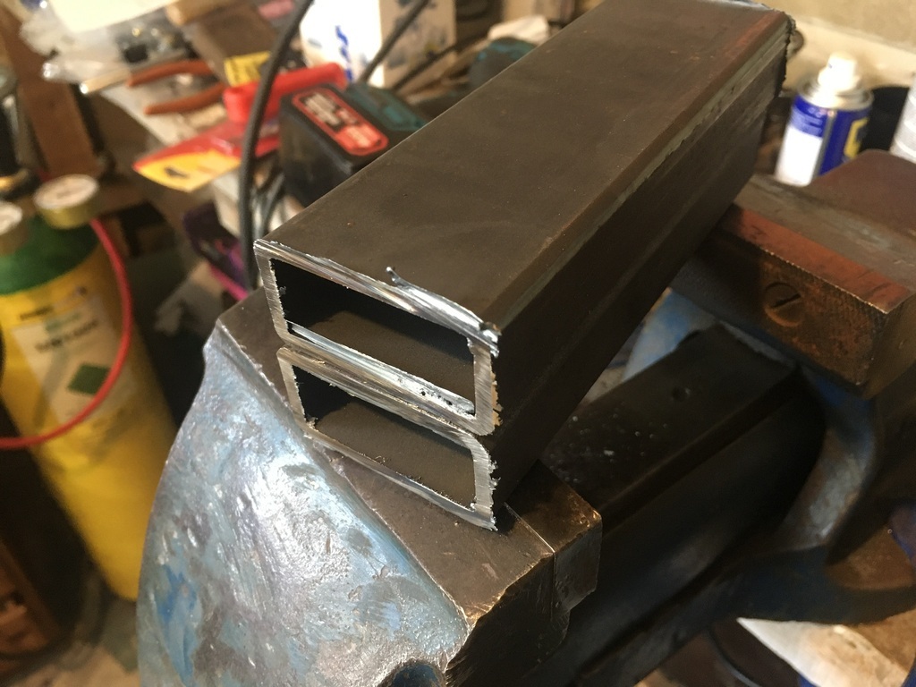
Used the chop saw to divide up the box section into a pair of smaller pieces:
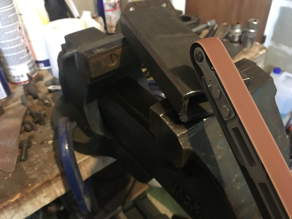
Cleaned up with the Chineezy finger file:
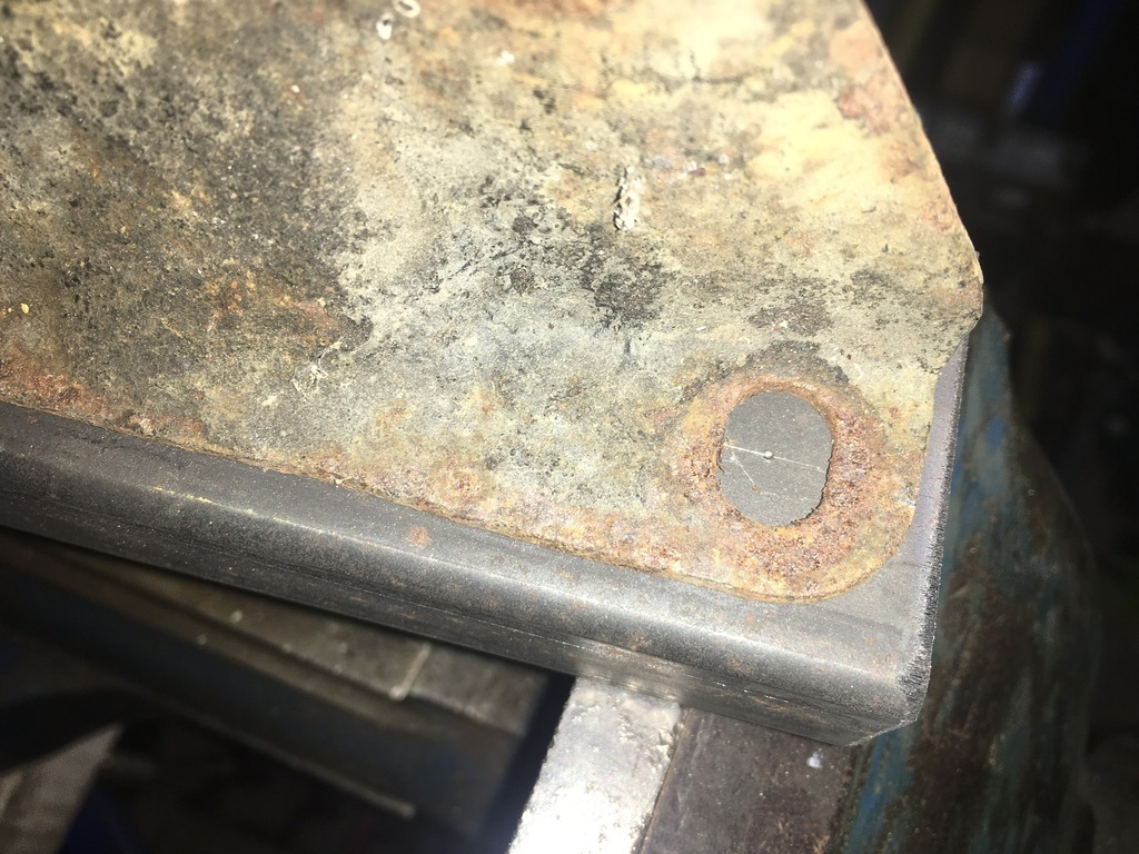
Marked out and centre-punched to match the suspension arm mounting plates with a slight offset to mount in the space available in the shell:
Drilled:
Brackets would mount like this:
And then sparkalized:
These are now going to go on the pile of other bits that are due to go off for plating, including the drag links from the rack, drop arms from the anti-roll bar, engine mounts, coil bracket and a few other bits that I've prepared.
Work on the rear suspension arm drive flanges and brake mounts is next, with the engine electronics awaiting cable and a few other bits as well as the dreaded exhaust manifold before a possible engine test...
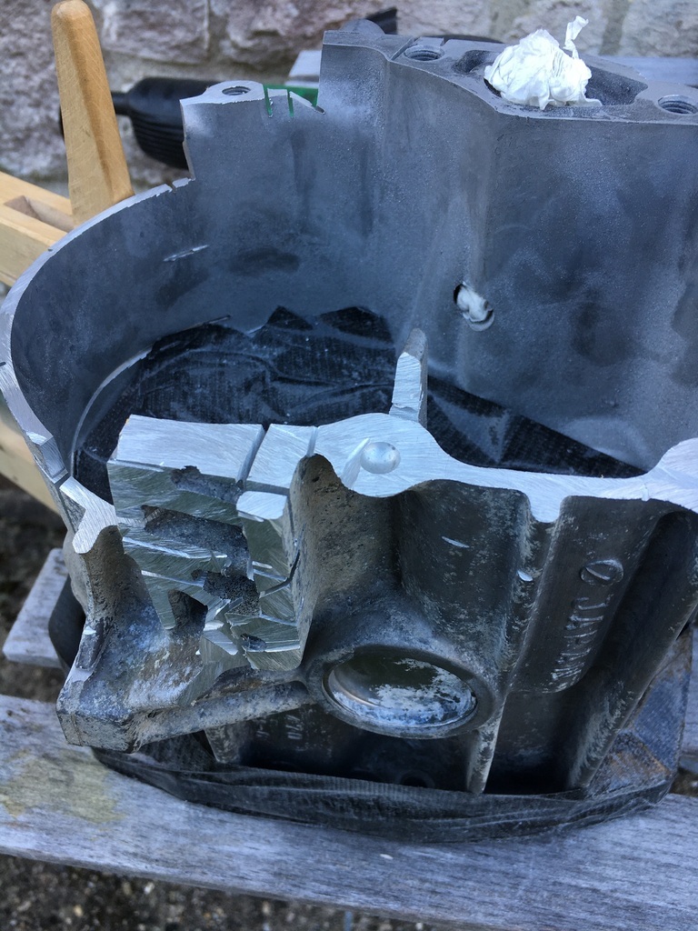
I have also been continuing with exploring the subaru gearbox option but am waiting on drawings to assess how feasible that is....although that hasn't stopped me keeping the neighbours on their toes with the practical side of checking it out with plenty of grinder action......more of which as and when...
 |
| |
Last Edit: Mar 20, 2022 21:24:39 GMT by 16grit
|
|
|
|
16grit
Part of things
 
Posts: 216
|
|
|
|
I'd like to say that this little update is a side project while I wait for my pile of bits to arrive back from the platers, but truth be told, I haven't even taken them there yet. So it's an update while I wait while lots of other bits are sitting in a cardboard box waiting to go to the platers..
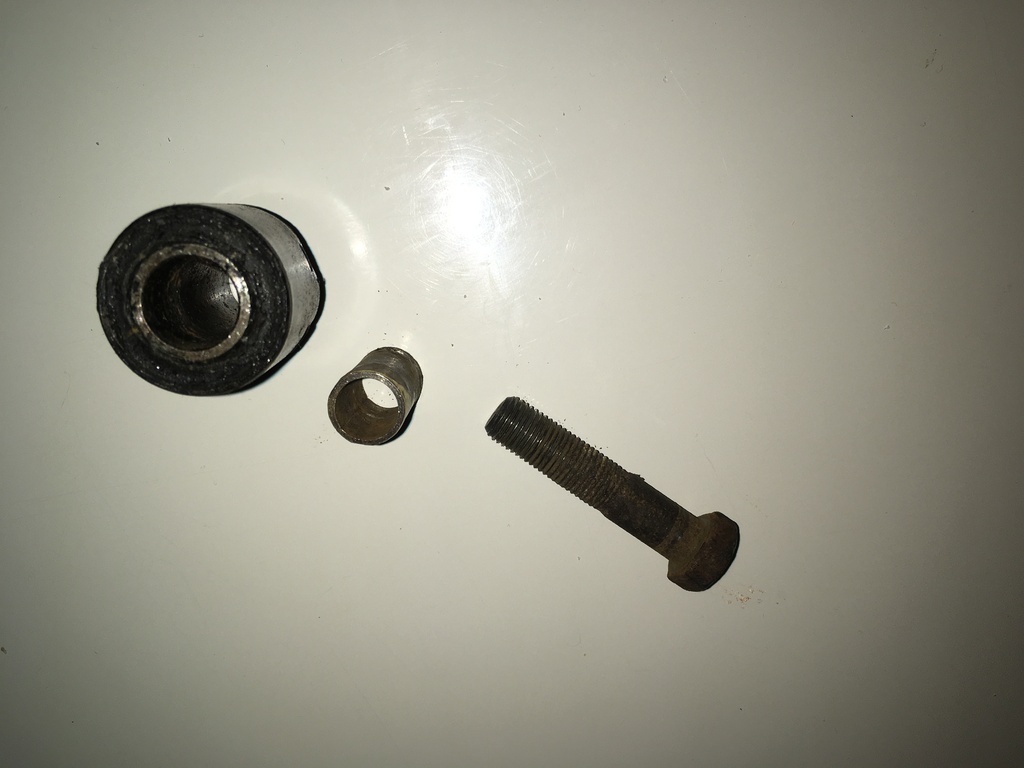
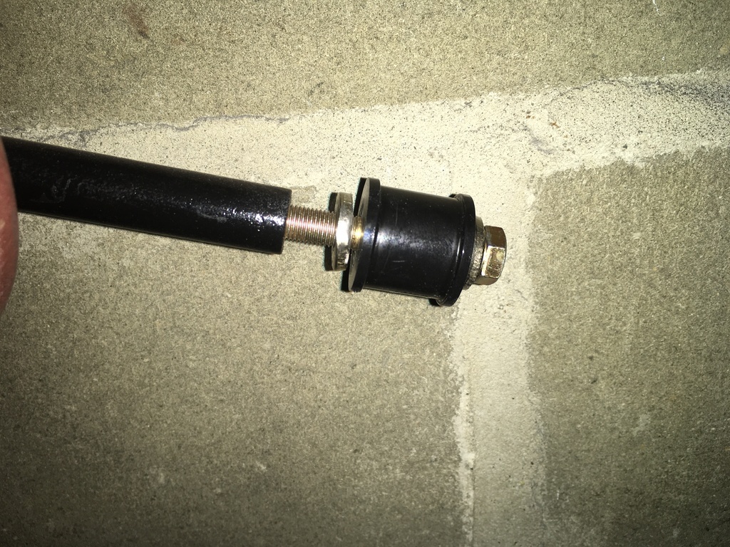
A few posts back I was dismantifying the anti-roll bar drop links that the original builder of the car had cleverly made by repurposing a pair of Hillman Imp steering rack drag links, shortening the metalastik bushes these contain and filling their centres not with gooey chocolate but some nattily machined brassy bronzey thin wall bushes.
Here is where the drag links originally lived as part of an Imp's steering:
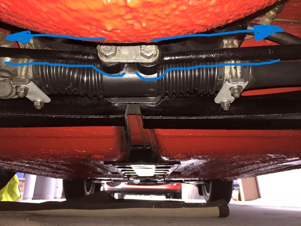
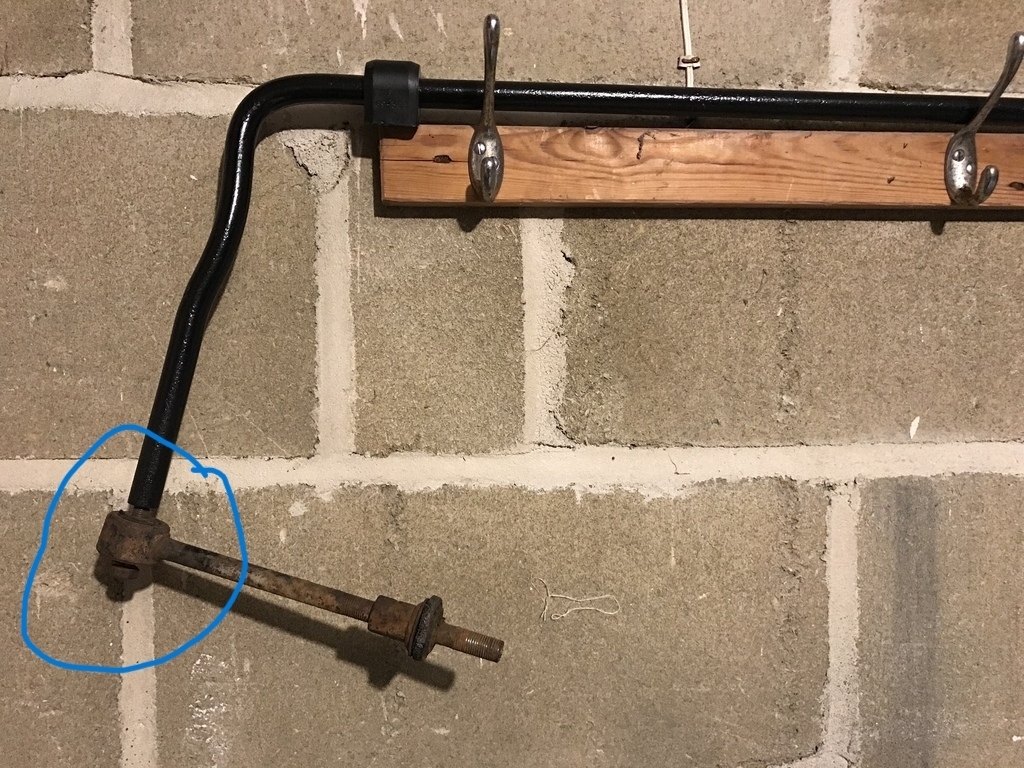
And here is the pair repurposed as drop links for the anti-roll bar installation on my car:
The area circled in blue contains this, the metalastik bush and the thin-wall metal mush which allows the link to pivot around the arm of the anti-roll bar:
Only problem being that after many years of (ab)use, the bush was no longer the kind of sliding fit that we all prefer...
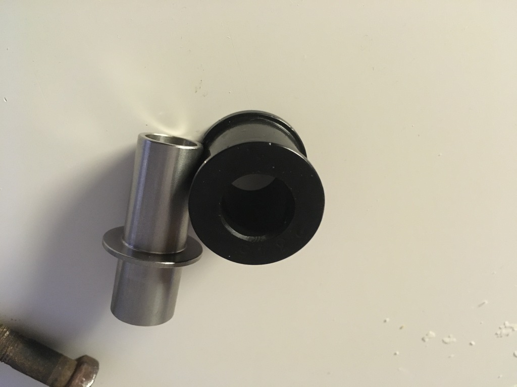
Now a lesser known fact is that polybushes are in fact available for the Imp drag links, when they are being used as drag links, meaning the bit sits around a craftily machined stainless insert that is in fact double sided, one to plunge into the rack itself, the other to hold the polybush in the drag link:
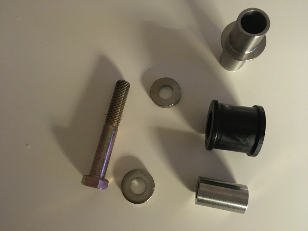
Ideal! All I would have to do is buy some new, longer shank part threaded bolts of the right length and some thick stainless 'containment' washers, and then measure the width of the bush and.......wait for it (you know what's coming don't you....) contact me favourite internet-based-lathesman to conjur up a paif of new stainless inserts that would use the bolt shank diameter as their ID and the polybush ID as their OD....
I took a chance buying an overly-long 3/8"-24 unf bolt in the hope that the unthreaded section would be long enough to give the bush a smooth running surface, and fortunately the length turned out good. I knew I would have to adjust the total length to suit with the angle grinder later.
Similarly, with the 'containment' washers to sit either side, I didn't want anything that would be too large and offer too much friction to stop the thing turning correctly, so the thick stainless washers were m8-holed, which I then had lots of fun and games with trying to drill/file/dremel out to the 9.5ish mm of the unf bolt.
Here are the bits:
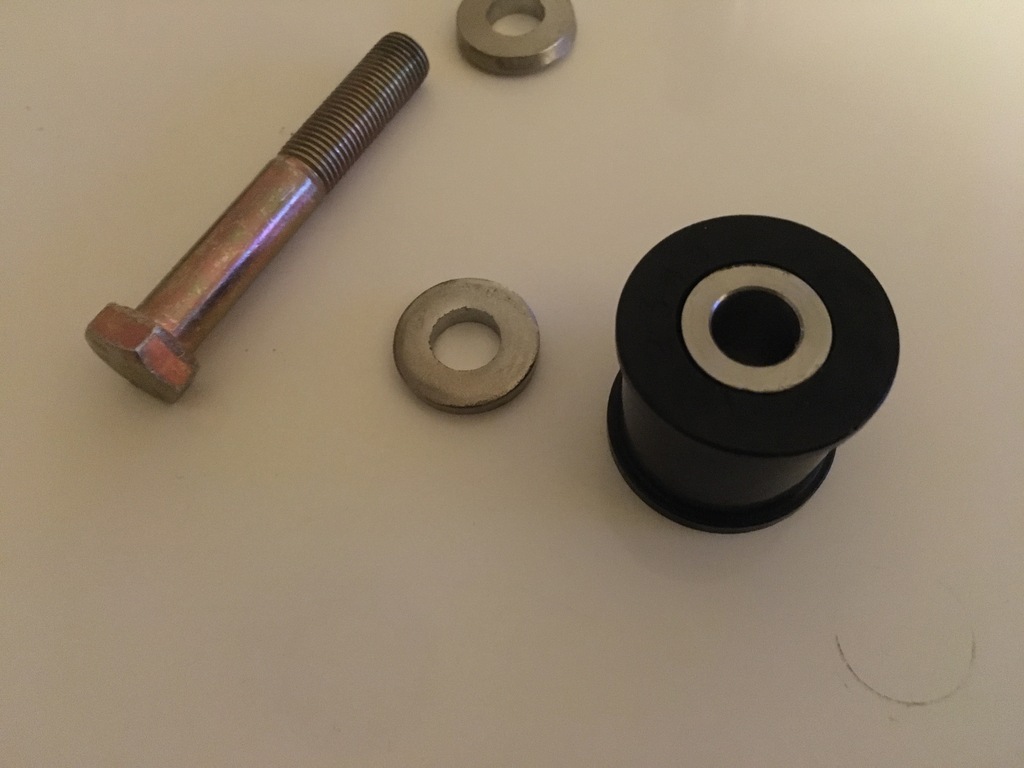
New stainless inserts in position:
And assembled onto the anti-roll bar awaiting the drag link itself:
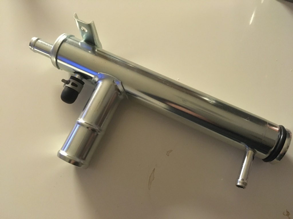
Parts arrived to move on a couple of other areas. Whichever gearbox I end up using, the size of the bellhousing compared to the original suzuki gearbox meand that I will not be able to use the original long external water rail which runs down the side of the engine out of the pump. I sourced this Suzuki Samurai part from India, although I'm having trouble dealing with the idea of the 90 degree bend it uses:
A bit of googling gave me the dimension of the O-ring seal that you can see fitted on the end, this feels a little loose. I am going to give the engine a bit of a clean before things go much further and after that I'll lube up the ring and see how tight the fit is.... (so to say)....
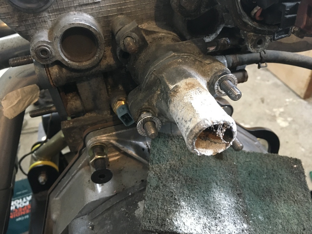
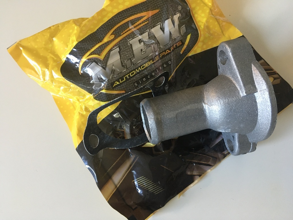
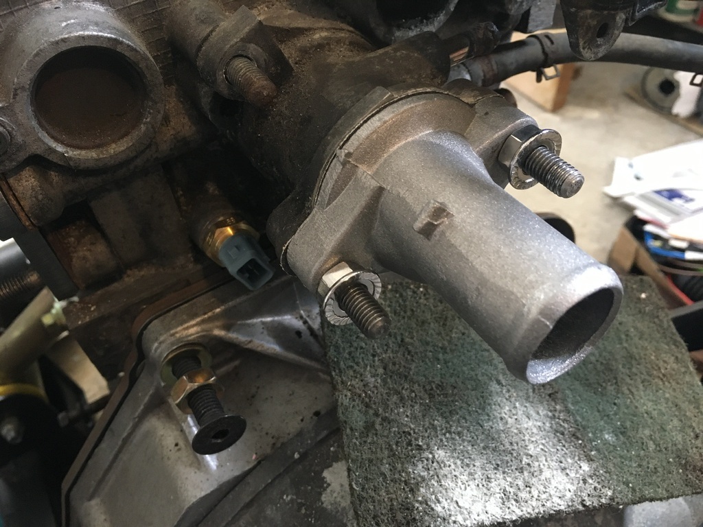
In more waterworks news, when I was playing around in the thermostat area while making up the coil mount I noticed that the elbow connector was busy turning itself into dust.
Here come the Indians to the rescue again, living in dread as to what this is actually made of....
And here it is fitted:
Thanks for taking a look..
|
| |
|
|
16grit
Part of things
 
Posts: 216
|
|
|
|
So, I found myself not just a little jealously watching this video
Rather than mess about trying to slot a Suzuki **CAR** engine in the back of their car, that particular Davrian is an example of a BMW **bike** engine, one of the flat-4 'brick' type motors, which a cunning chap up north mated with the original Imp gearbox...So there is me, light years away from having a Subaru gearbox playing nicely in the back of mine and beginning to wonder if even the idea of one was really just some kind of gateway drug that would eventually, inevitably lead me to going FULL SUBARU...I took a reality shower and spent a little happy time with my neat AM coded VW box and wondered whether maybe, having only a few posts ago derided it on as many levels as I could think of at the time, whether I needed to admit my crass, rash stupidity 'reassess my position' on the VW box, it probably being just the kind of gearbox I needed to see my car turned from project into an actual running, driving vehicle .
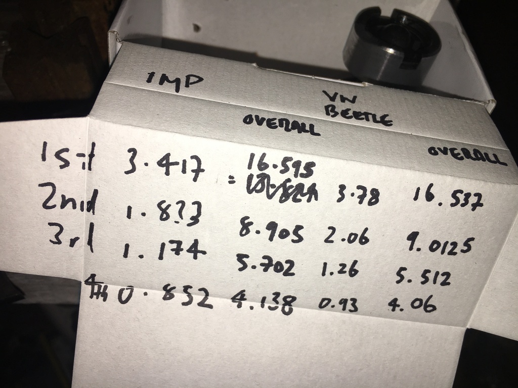
Living as we do in an 'evidence led' world I thought I'd show you the fruit of some of my in-depth 'research', presented, rather mirthfully, on a fag packet, on some spare cardboard from a Anchor Butter multipack. It only turns out tha tfar from being the rubishy-ratioed crystal chandelier that I once thought it was, the AM code 'transaxle' has some really neatly spaced cogs...that are, er......, in fact JUST LIKE AN IMP's, which means that I too could be zooming around my local circuit making great car noise even sooner that I had thunk possible....
And before someone at the back shakes their head with a sharp intake of breath, I'd just like to add that Imp boxes are reputed to have equally weak diffs...
With such beautiful mental gymnastics opening up such wonderful vistas to me I felt sufficiently energized to turn my attention to the car's rear arm and brake setup, that part of the car having remained worrying absent from this collection of musings so far...
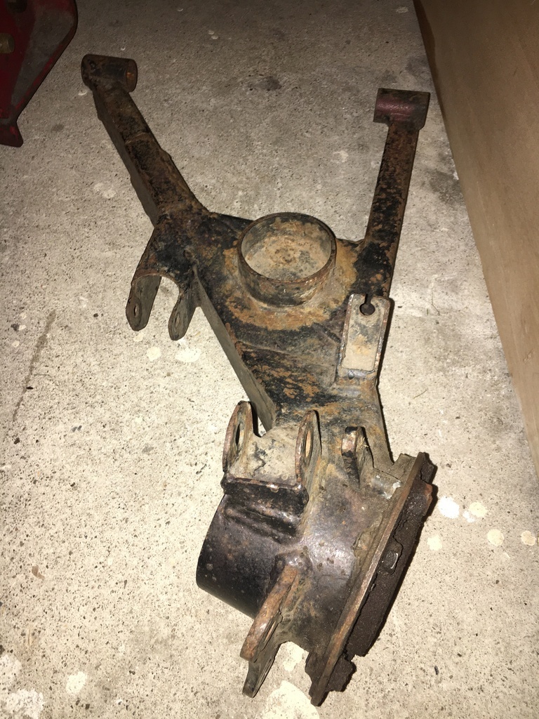
This is a photo of one of my pair of spare rear arms.
And again...
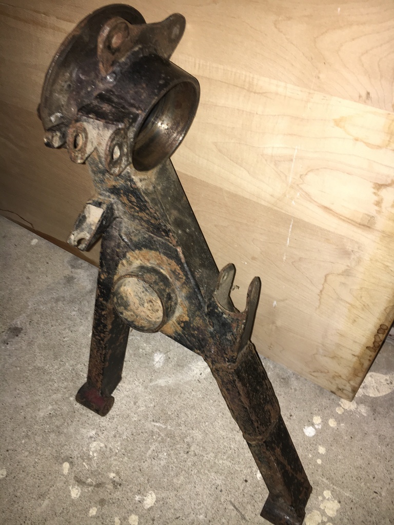
Like my other pair of Davrian fabricated arms, these use the Imp pivot bushes and dimensions and an Imp type rear spring (rather than coilovers), and TWO rear shocks PER SIDE (Oooh La La, soooooo Group B...), but these ones are full on Autograss style with cylindrical tube bearing mounts - and 100mm **FORD** flanges...
"Googling it til I made it a real thing" demonstrated that yes, there was such a thing as a 100mm CV joint that would fit my early VW Typ1 based 33 (?) spline drveshafts, more of which later.. in the meantime, here is where they are going to attach...
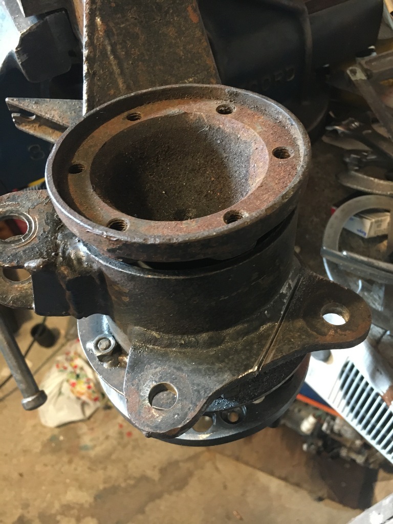
That just left the question of brakes. Just visible in the pic above is the oringal brake caliper mount. This was going to need to go!
And so, with so much renewed enthusiasm that I'm thinking of reselling it, I finally made my way towards ACTUALLY PICKING UP A TOOL.....
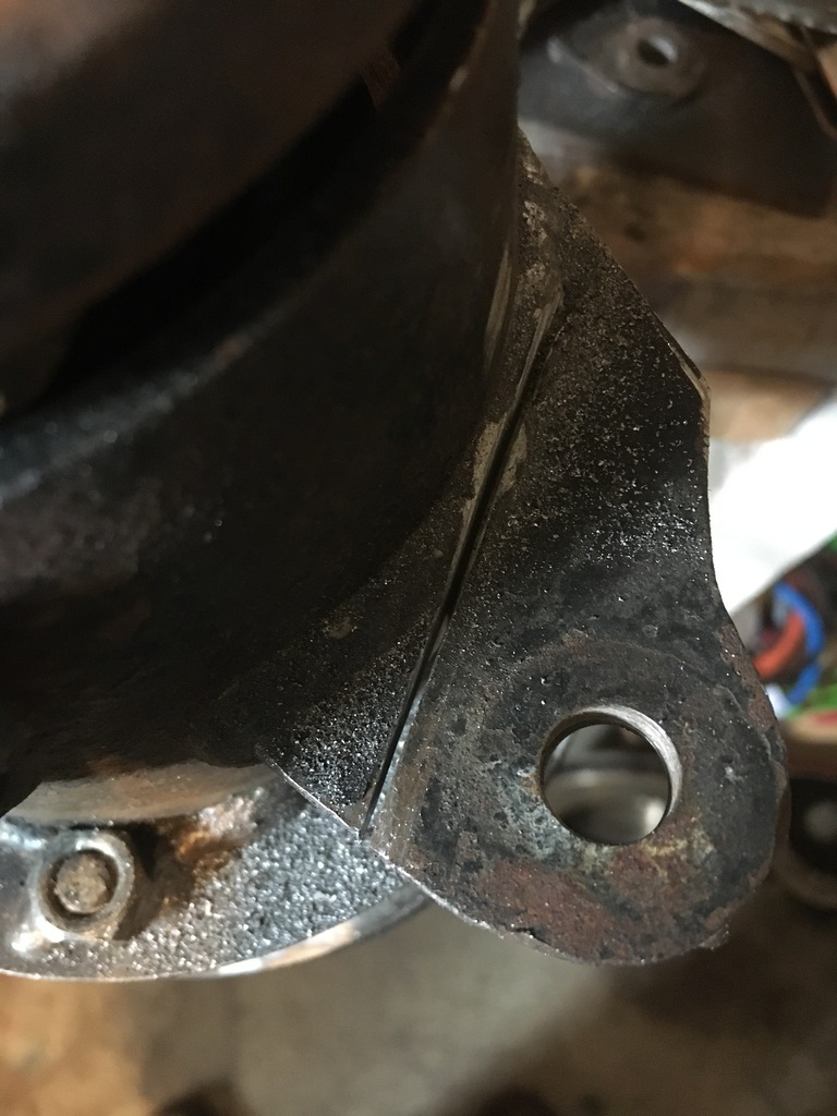 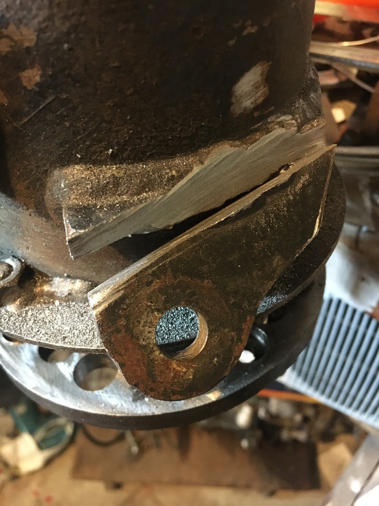 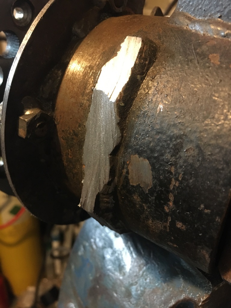 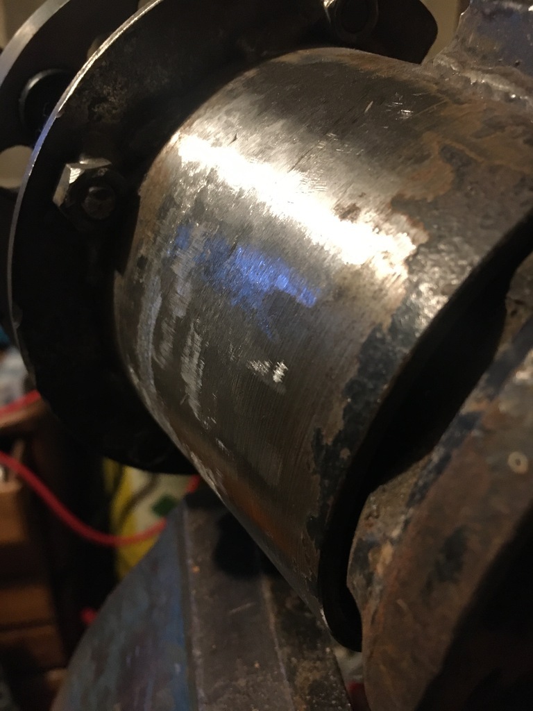 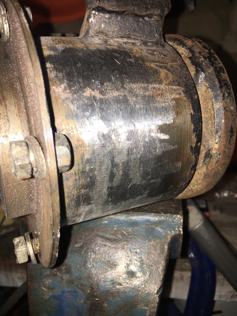
Now, even though I said above that my first choice was to use RS turbo / Sierra 60mm piston sliding case iron calipers and their VENTED 260mm discs ALL ROUND, niggling doubt was beginning to infect this particular choice too....(nothing to do with a recurring dream I seem to be having involving some East German hammer throwing 'girl' and rather too much underarm hair) whenever I've been thinking about all the weight of my cast iron escort brake calipers swinging around right on the end of the arms..... SO much so that I snagged these, 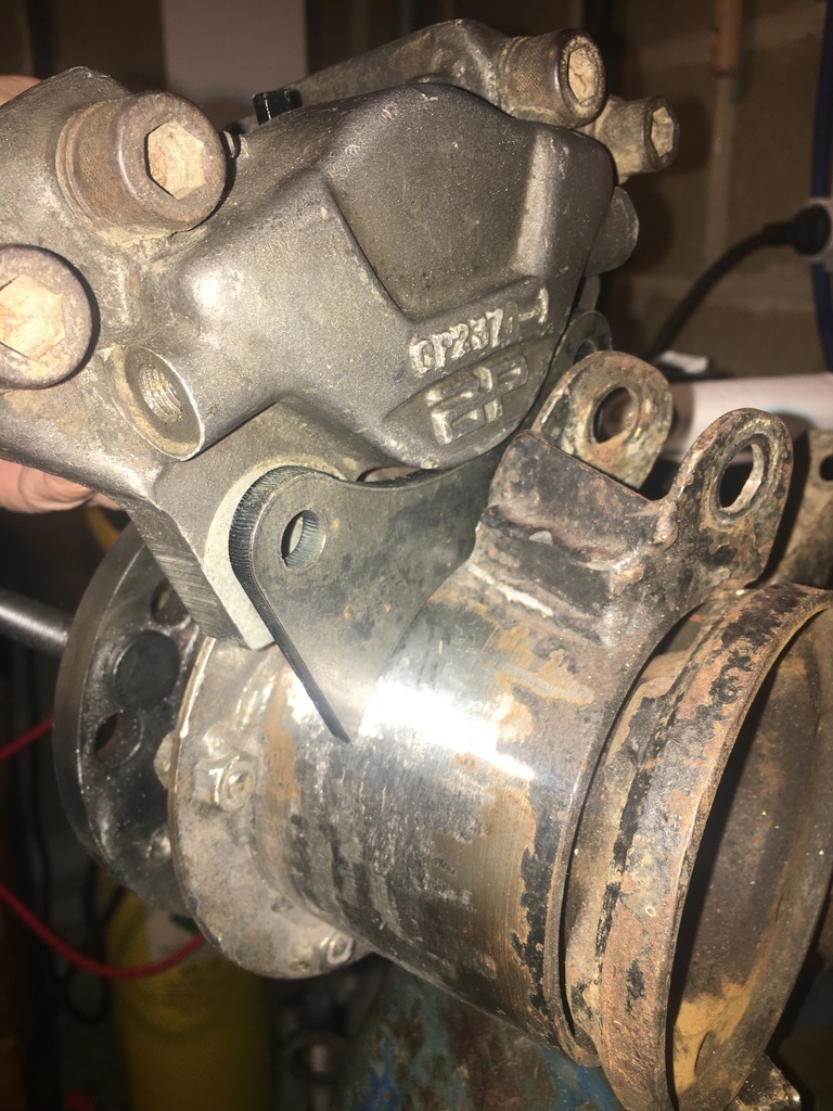 Purely to keep my options open.....but which might provide just the solution I was looking for " if only I would show a little commitment...."... Using the (heavier) rs turbo discs and calipers on the back has an attractive symmetry about it, and might offer the choice of being able to rig up some kind of motorcycle internal expanding handbrake arrangment in the disc bell itself. The alloy calipers have 54mm pistons and would might use a marginally lighter disc. I'm going to get some of those discs to mock up what it is going to take to use the alloy caliper setup, but as a minimum its going to mean a new drawing for new caliper brackets to be made etc.. 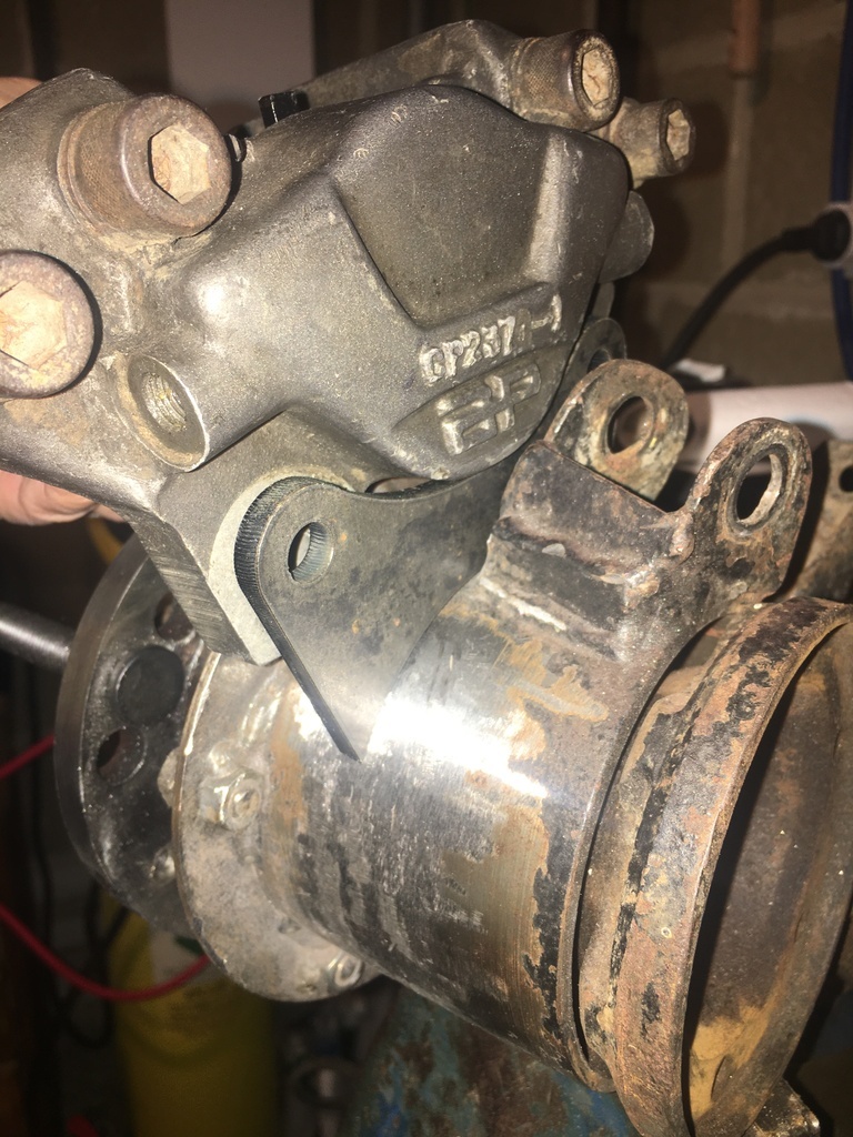 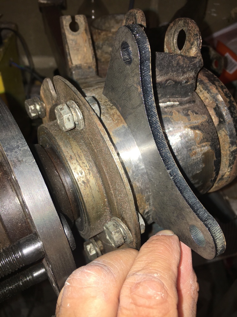 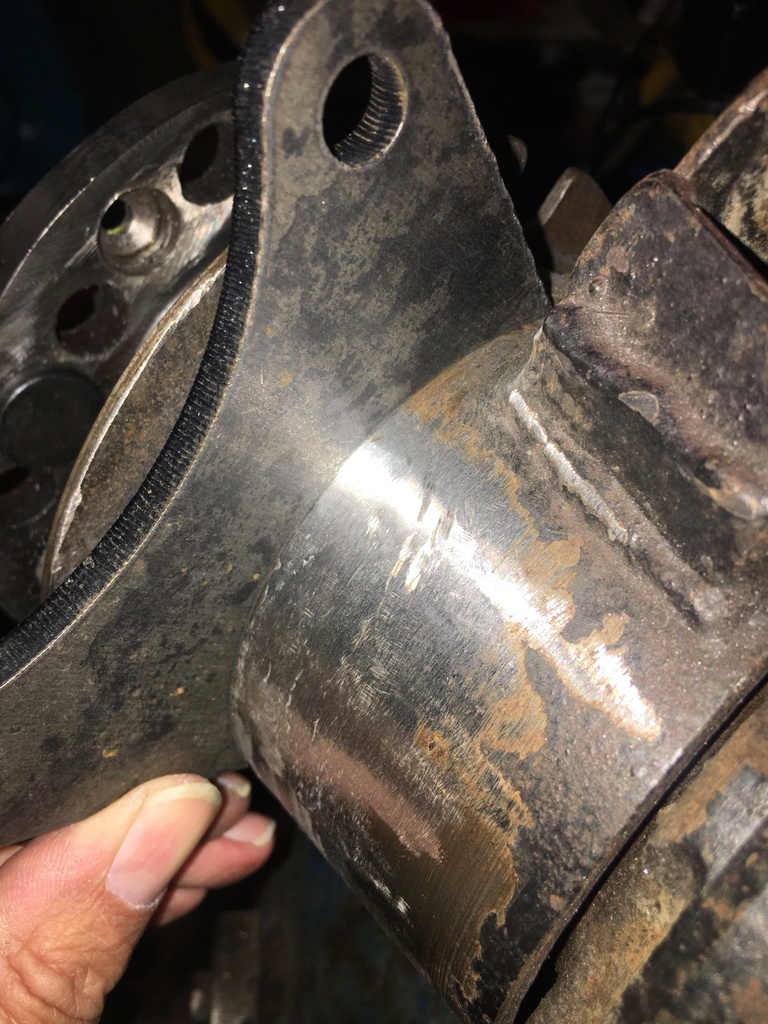
Thanks for tuning in...
|
| |
Last Edit: Jun 19, 2022 6:25:53 GMT by 16grit
|
|
16grit
Part of things
 
Posts: 216
|
|
Jun 19, 2022 11:20:46 GMT
|
little bit of progress to update. i received a box full of my bits back from my platears. Quality this time was a little disappointing, but most of it is at least useable: 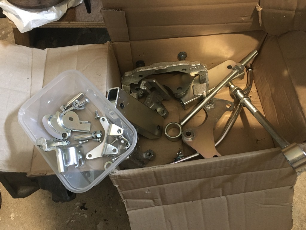 turned my attention to my coil mount: 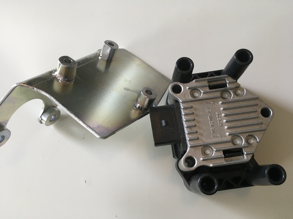 Some ebay sourced Allen screws and nylocs completes this little unit: 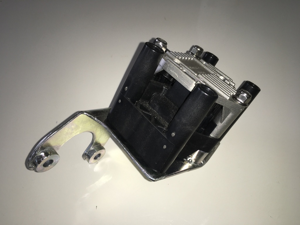 and 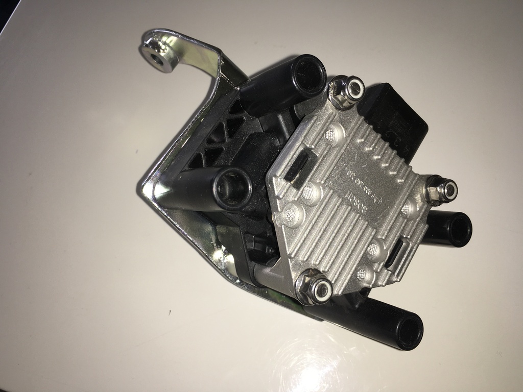 Steering rack was up next. According to a Motoring News test of the car back in the day, the rack I have reputedly had a Jack Knight quick rack / high ratio pinion fitted. Laughably, I forgot to check this and do a tooth count when I replaced the rough-feeling bearing and seal I found: 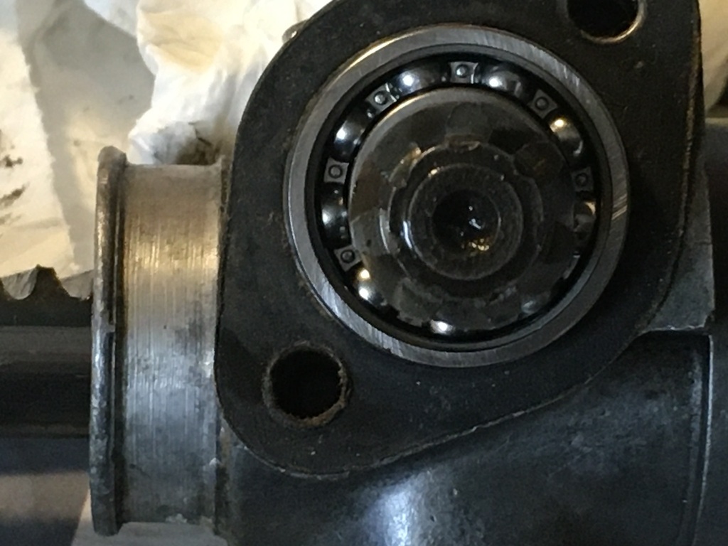 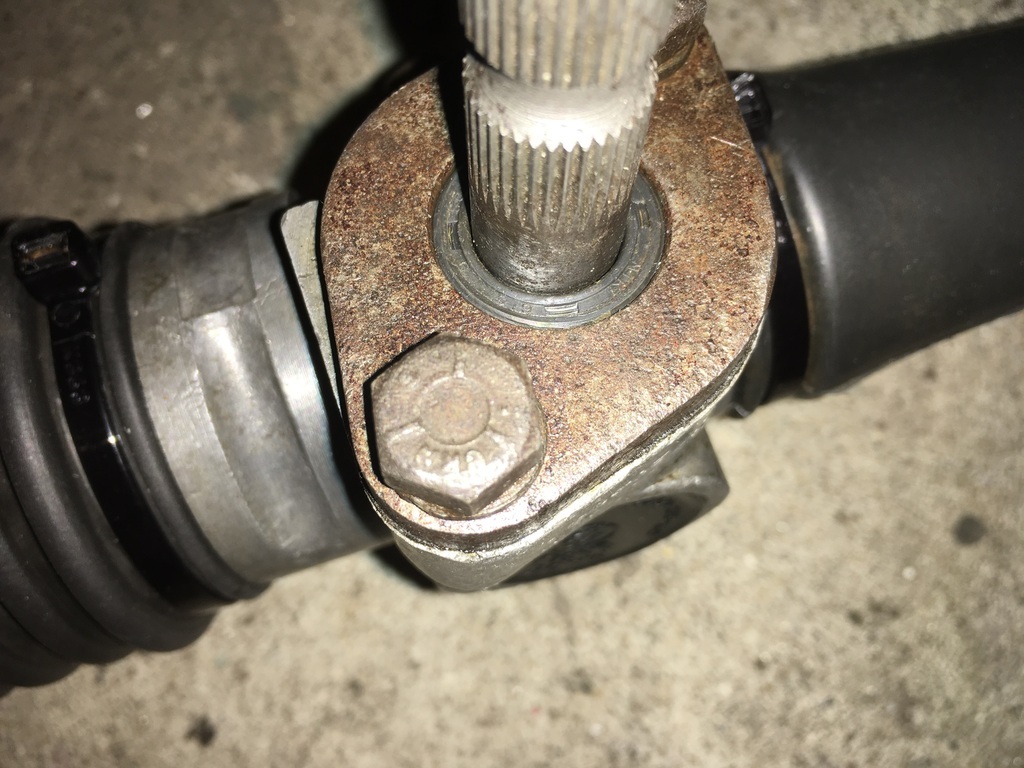 Once the new bearing was in the rack didn’t feel to have any play in it so I didn’t go on to re-bush it, whether this will prove true when it has some load on lit only time will tell. I gave the paper gasket a light wipe with a little Wellseal and put it back together. I had previously pushed out the rubber bushes from the drag links: 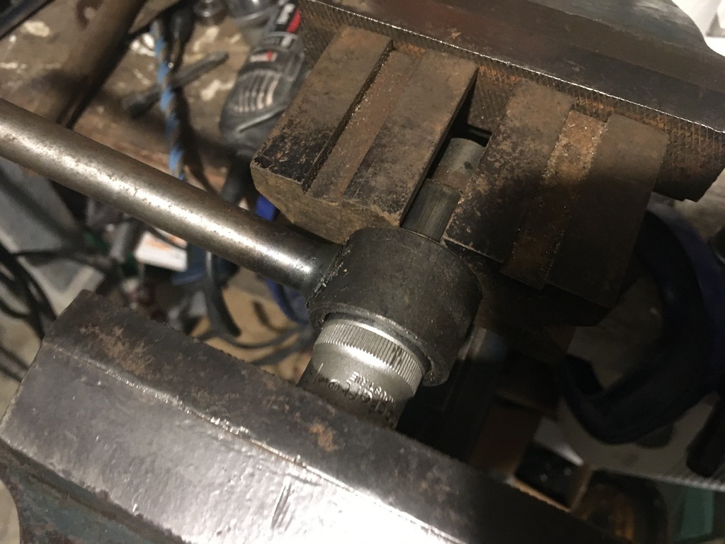 Even after removing the rack gaiters from the rack they looked serviceable, so I put them back on and fitted same polybushes I described above that I am also using in my anti-roll bar drop links; 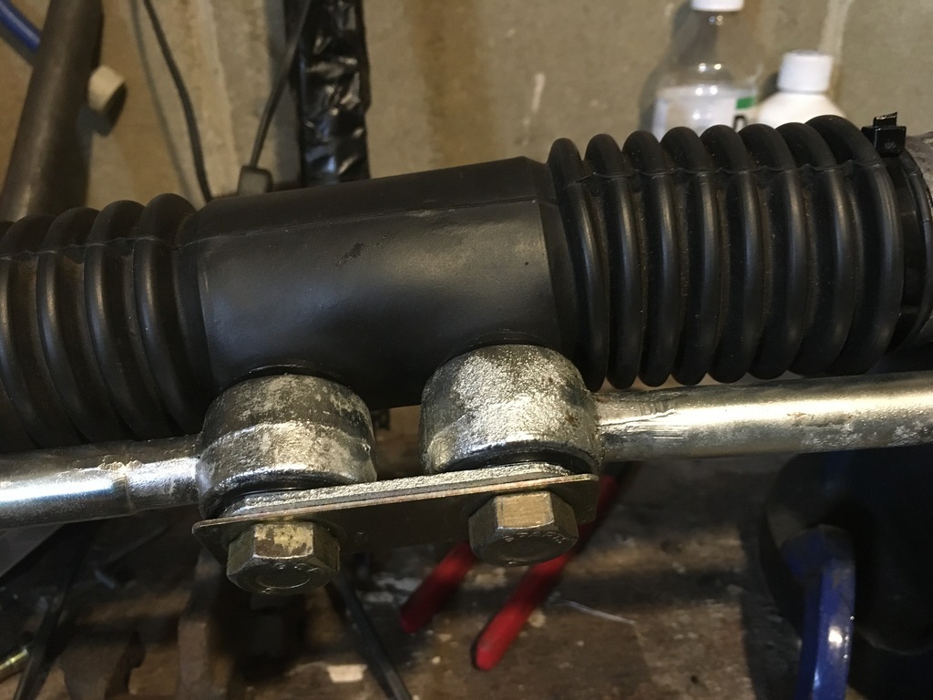 with the rubbers partially fitted and the central arms on I could put some lubricant in, opting for Land Rover swivel grease rather than EP90 purely in the grounds of trying to avoid the smell of EP... 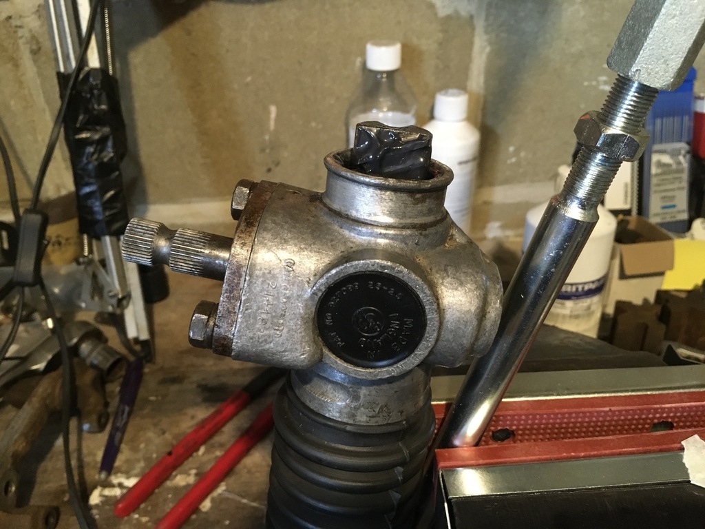 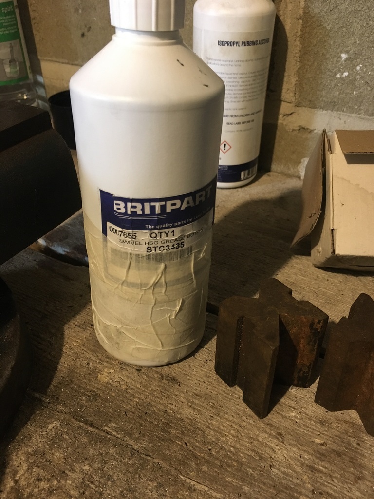 just a bit more than 3/4 of that went in. That left sealing the thing up, I opted for cable ties, smidgeon under 5mm wide and then snipped to the quick in an attempt to stop the inevitable gouges in my arm when I refit the rack 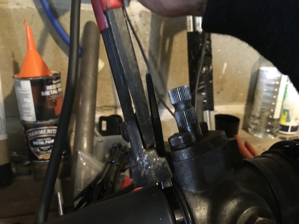 That left putting some paint on the rod ends: 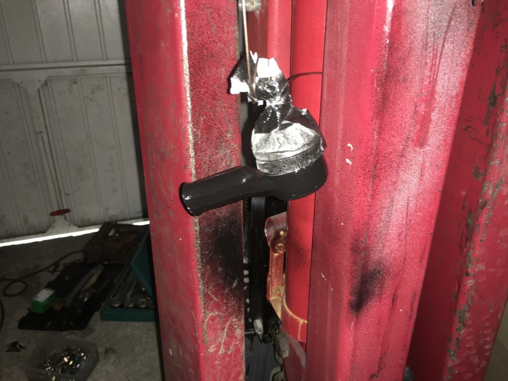 and the rack is almost ready to go back in: 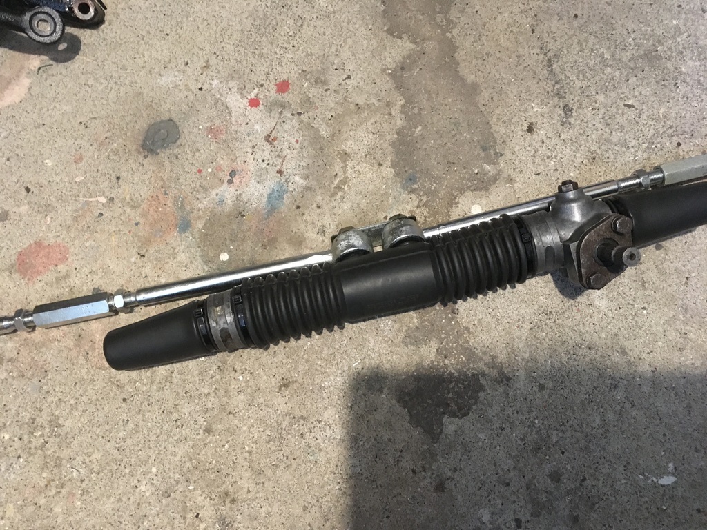 When I disassembled the rack I took some measurement to aid in putting the thing back together - not definitive but hopefully enough to get the wheels pointing in the general direction before setting it up properly : 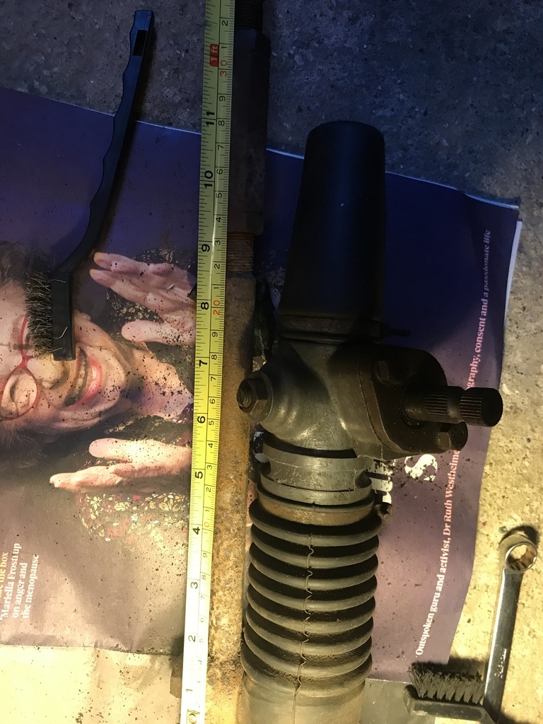 While all this progress has been cool, my rear arm, hub and brake set up is throwing problems at me - with a few giggles to. The guy that usually does my cutting drawings is now in the frontline in Ukraine, so I’ve been forced to turn elsewhere. His replacement sent me a drawing which generated this comically oversize caliper Mount......:-) 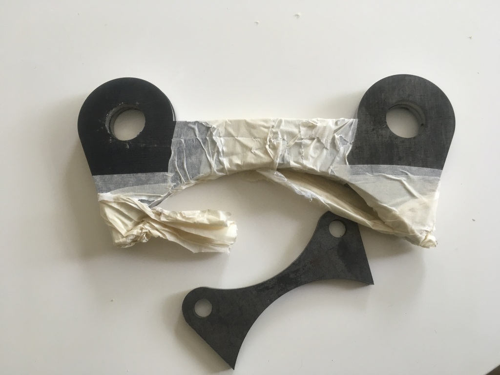 On another happy note, My tig mojo may have been rekindled...by a pair of £2 specs. For the past several months I had been getting increasingly frustrated with my tig, I only use my set occasionally anyway, so am far from on it every day, but in the past I’ve been able to get into the groove again quickly. Though I’d try a pair of reading glasses off eBay to see if that made a difference and presto! the difference is dramatic, can see what I’m doing again... Til next time.. |
| |
Last Edit: Jun 19, 2022 12:03:49 GMT by 16grit
|
|
|
|
|
Jun 19, 2022 13:09:32 GMT
|
|
You can buy "built" Beetle gearboxes off the shelf that will take a lot of power, even five speed conversions.
|
| |
|
|
|
|
|
|
|
|
Any potential news on this?
|
| |
|
|
|
|
|
Feb 17, 2023 21:33:15 GMT
|
|
Please keep up the updates. i am jamming a Aygo engine into a Kitten and frankly there is a lot of cross-over with your project.....
|
| |
|
|
16grit
Part of things
 
Posts: 216
|
|
Jun 11, 2023 19:45:17 GMT
|
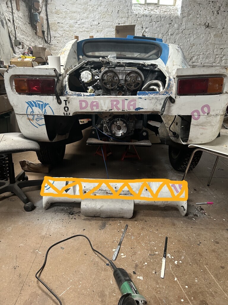
Well, a whole year later and here's the tiniest thing of an update. Thanks to the folks out there that have asked about the status of the project. Finally got into the workshop today and decided to saw up the (original) rear bodywork to a more exhaust-accomodating profile. I am planning to eventually use this rear section as a male buck to glass-up a new lighter-weight clam in this shape, as this one must weight 20-30 kgs. Starting point and marking out the section to be removed 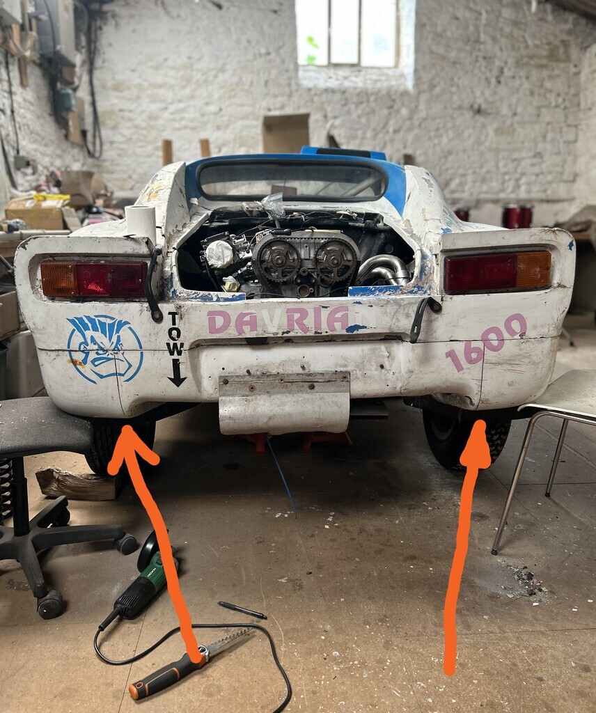 Marking out 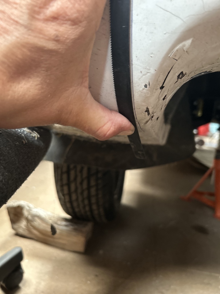 Ready to cut 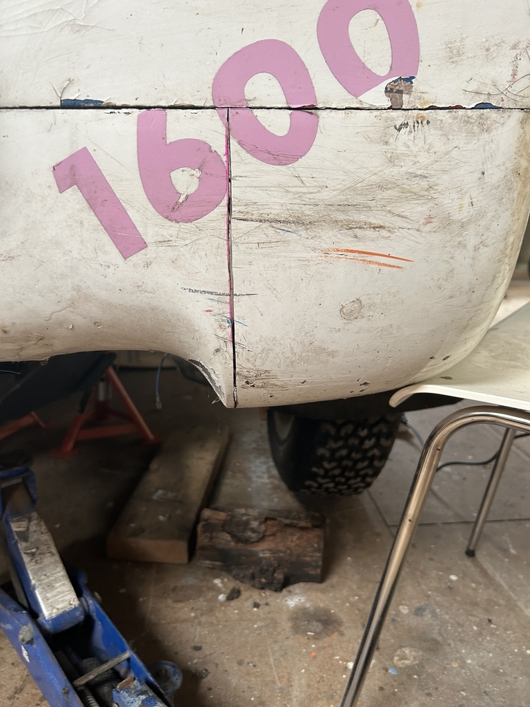 I then used a combination of the disc cutter and some wrapped hacksaw blades to the do the vertical cuts and the horizontal seam of the upper clam and lower valance which actually started as separate mouldings although they had been bonded together subsequently. Leaving me with this 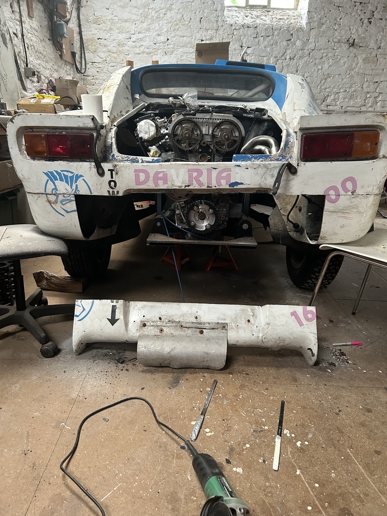 From the shape of the cut it is probably painfully obvious that instead of working on the car and updating things here my free time has been filled with far to many youtube roof-chop videos.....
I am going to trim the upper 4 inches or so from this piece and then rebond this to the rear panel as shown below
The plan first though is to get on and put the exhaust together, then modify the outer profile of the bodywork to give as much space as possible between the two. Thanks for taking a look! |
| |
Last Edit: Jun 11, 2023 19:55:42 GMT by 16grit
|
|
16grit
Part of things
 
Posts: 216
|
|
Jun 17, 2023 19:07:36 GMT
|
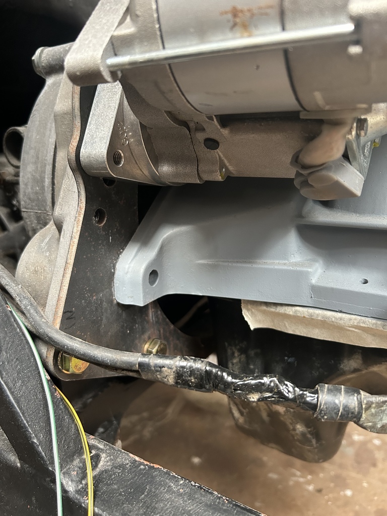
Over the next ten days or so I hope to be able to spend a fair amount of time on the car, with the aim of getting to the point where all the basics are in place for the engine to run. There's heaps to do to make that anywhere near a reality though. The battery sits in a moulded 'well' in the front boot area, placing a bit of weight over the front wheels. The idea is to run a pair of short heavy duty positive and negative cables up to some thru-bulhead fitting (via a cut-off switch) and then ownards to a maxi-fuse power distribution box. Having checked the current price of new heavy duty battery cable (!), I've decided to re-use the existing heavy duty positive cable that feeds power back to the starter/alternator. With the shell being 'all-glass' without a separate chassis and only a steel engine cradle, earthing duties are taken care of by the built-in rollcage front to back. So here is the 'twin-ply- double-do-nut front to back heavy duty positive cable' poking its head into the front luggage compartment. 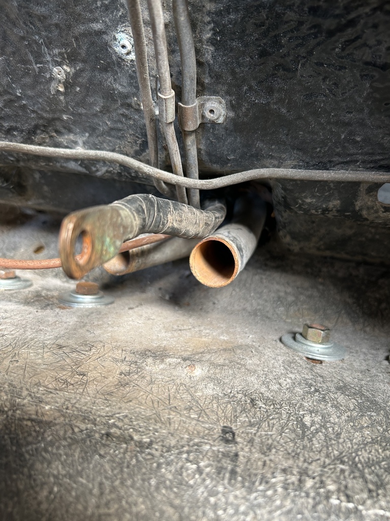 Here's the view from under the car. The idea was to pull this out 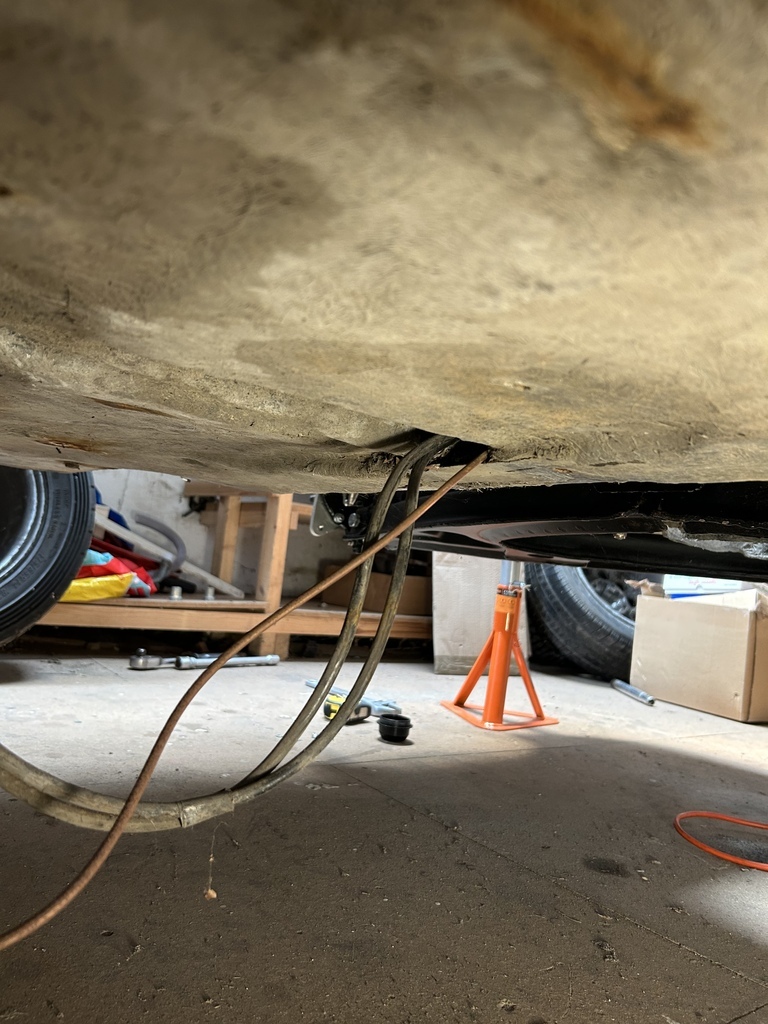 Like so 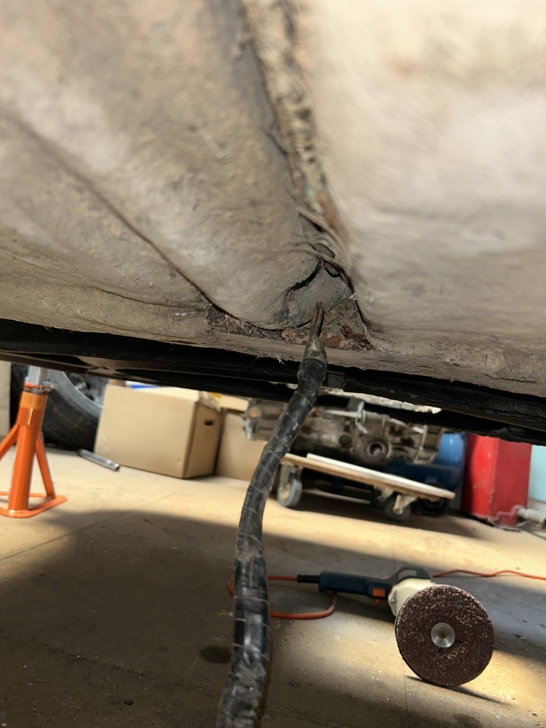 Then re-route the cable into the passenger compartment using a hole occupied by the twin throttle cables etc, where it could be attached to the maxi-fuse box I'm going to use to divvy up the power for the main supply circuits
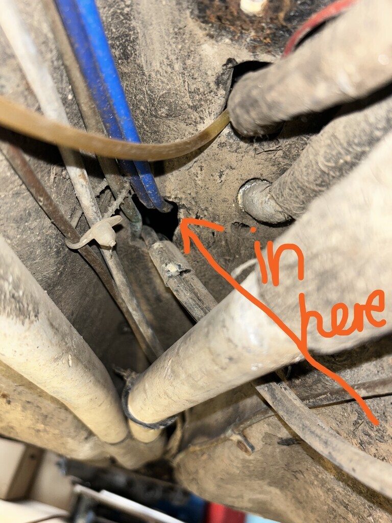 Having prostrated muself laying on my back in a very hot workshop on such a humid day, the car gods got their shot at a little schadenfreude, coz when taking the chance to indulge myself with a little photo taking... 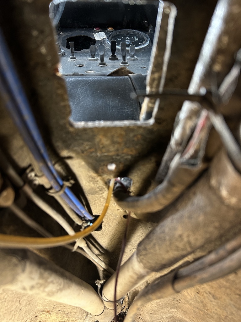 I noticed that the wiring loom under the car had clearly seen a little more heat than was good for it as some time, probably, hopefully, the last time anyone else tried to start an engine in the car... 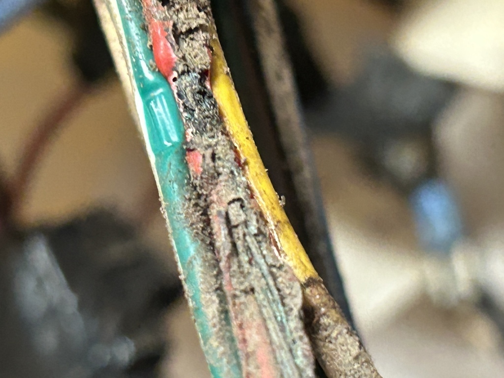 and.. 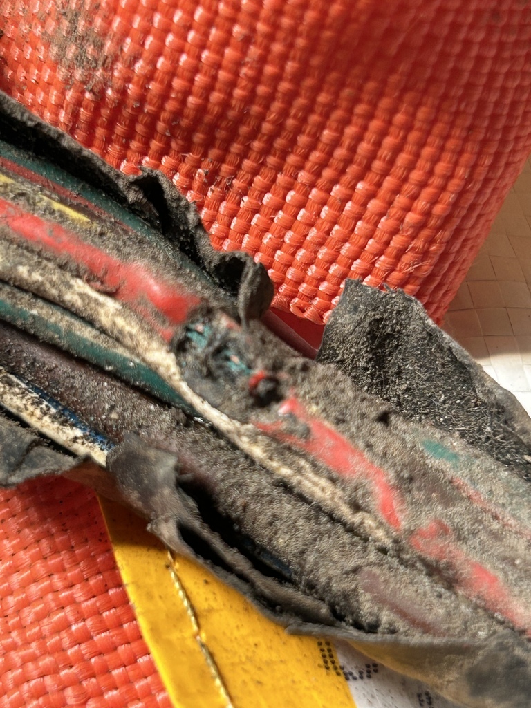 So instead of moving on to install my power distribution fusebox I ended up pulling the loom out from the back of the car. Now truth be told a good deal of this was likely to be replaced anyway with the standalone ecu setop the car is getting, but it meant I had to change tack today. With some pretty heavy heat damage the only option is to cut out the damage and rewire as appropriate. Before that can happen Ive had to start to make some notes of the circuits in the old loom that I do want or need to keep, and that's where things stand as of this evening. 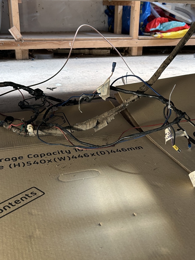
Thanks for taking a look
|
| |
Last Edit: Jun 17, 2023 19:15:24 GMT by 16grit
|
|
16grit
Part of things
 
Posts: 216
|
|
Jun 19, 2023 21:04:41 GMT
|
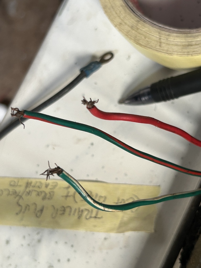
So, little bit of progress on the loom today. That meant starting to reinstate the wiring that runs to the back of the car to feed the tail light/brake lights/indicators that are attached to the detachable clam. With the rear bodywork being detachable, the cunning chap that built the car used a trailer wiring plug and cable setup, something that might have looked like this in its shiny newness back when flares were not just on the side of your car, but on your strides too... 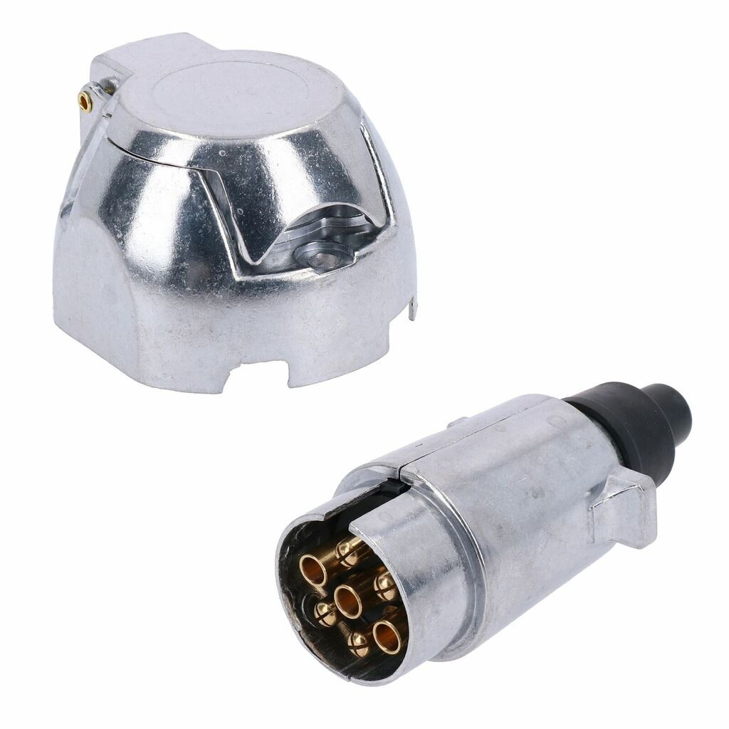 What I actually had when I took the car apart... 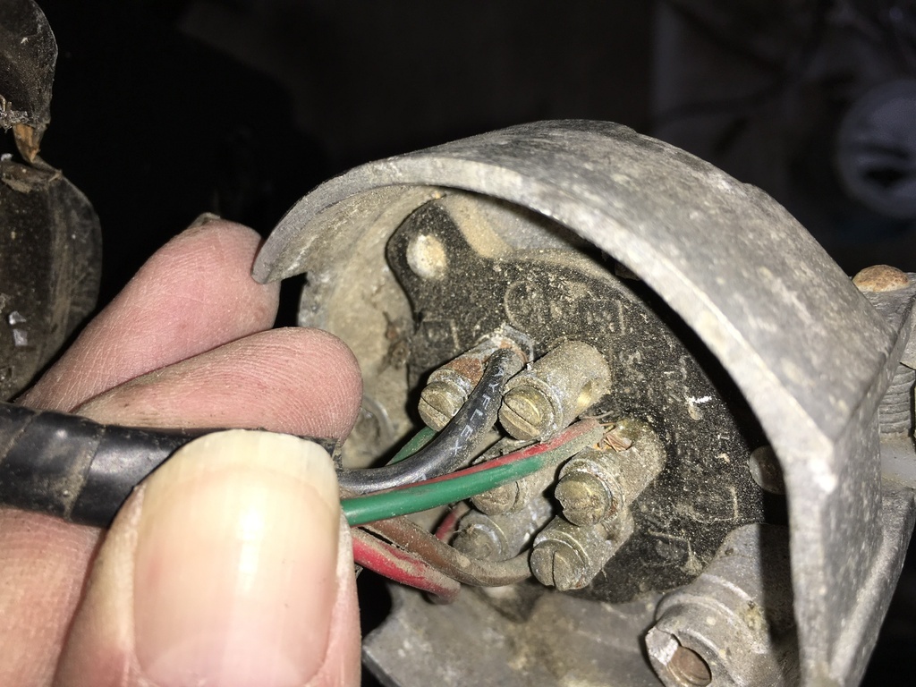 And what was on the main, car side of the loom, these three (plus a short earth to the rear cage which stayed attached to the cage...kindof)
Having some suitable wire on hand I made a start on replacing this section of the loom, thinking that I could cut the existing wiring high up behind the instruments somewhere where it was least likely to have been damage by the heat. To get at any of that meant a busy Sunday sat in the car slowly working to remove all of the stupidly sticky 70s insulating and masking tape around the loom in the tight spaces behind the dash so that I could check for wiring damage and being able to single out the individual wires that I would be replacing over the coming sessions I decided that it would be worthwhile adding in an 'extra' wire also, perhaps for a reversing light or some other type of auxiliary lighting in the clam. The only remotely suitable connectors that I had were the weather-proof type, which meant a good half hour googling the correct orientation of the pins in the connectors etc, and through a process of elmination that destroyed three or four pins, the best of my crimping tools to fit the pins to the wire I had. Starting point.. 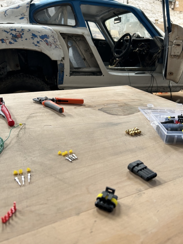 Which after more time than I care to admit, became this.. 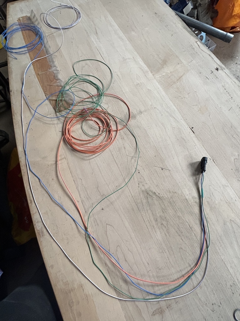 After lots of this 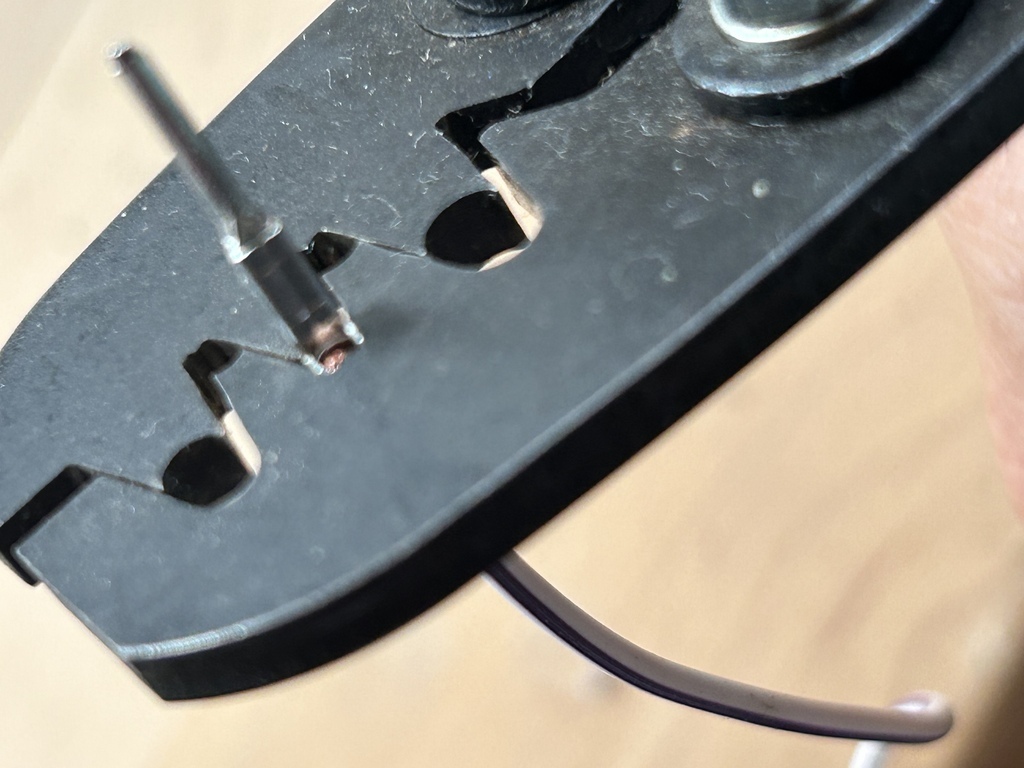 And this 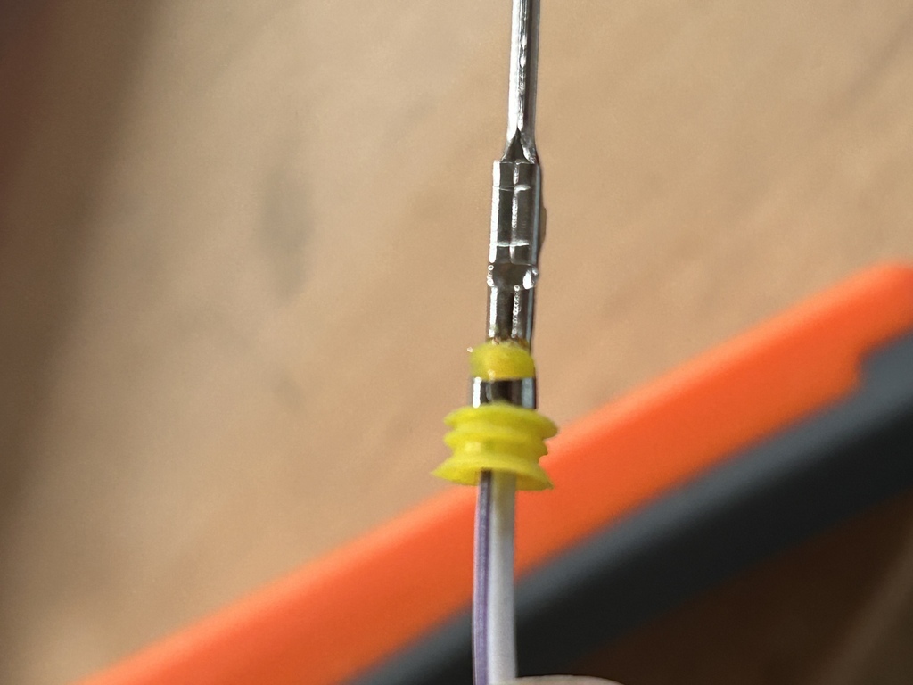 To this 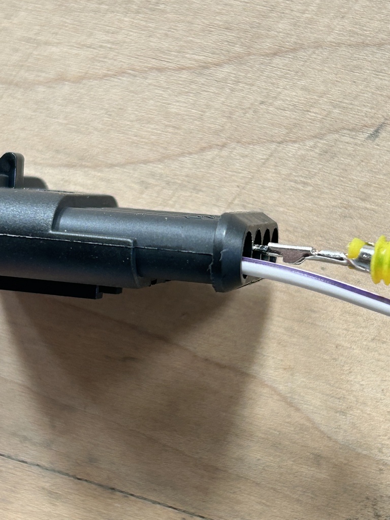 And this 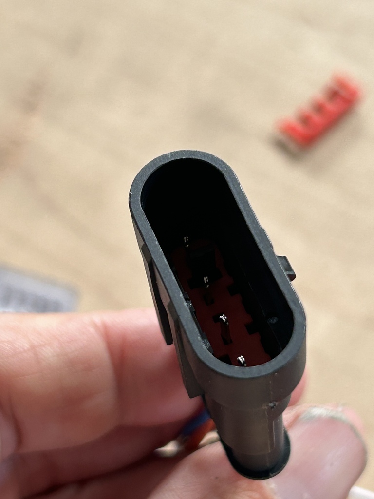 I then cut and crimped up the existing wires behind the dash 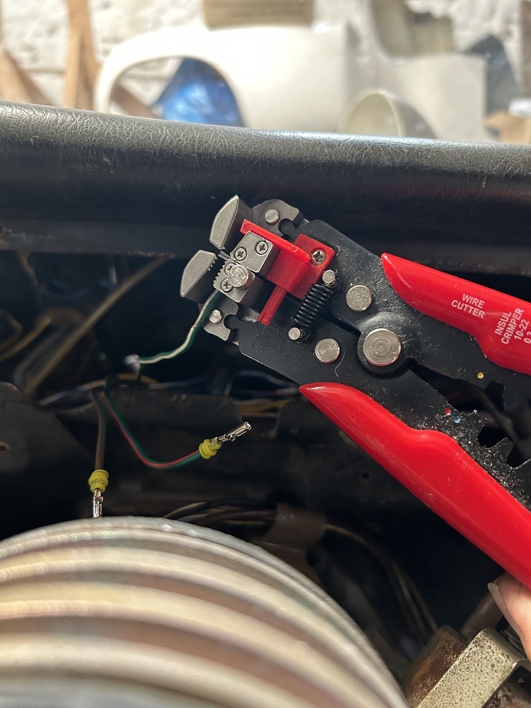 With that complete, my attention turned to the centre console section. I have taken the decision to remake this, rehoming the existing switches shown here 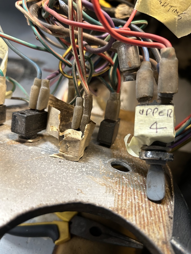 in a new alloy panel but making space for some relays here too. Although it looked all 'driving gloves and chrome bezel 60s Brit sports car chic', the speedo unit that can be see in the earlier photos up above had obviously not worked for a long time, so that has been removed. No decision taken on what is to replace it yet, apart from a trip meter that I do have in a box somewhere that might be suitable. Measuring up for new panel 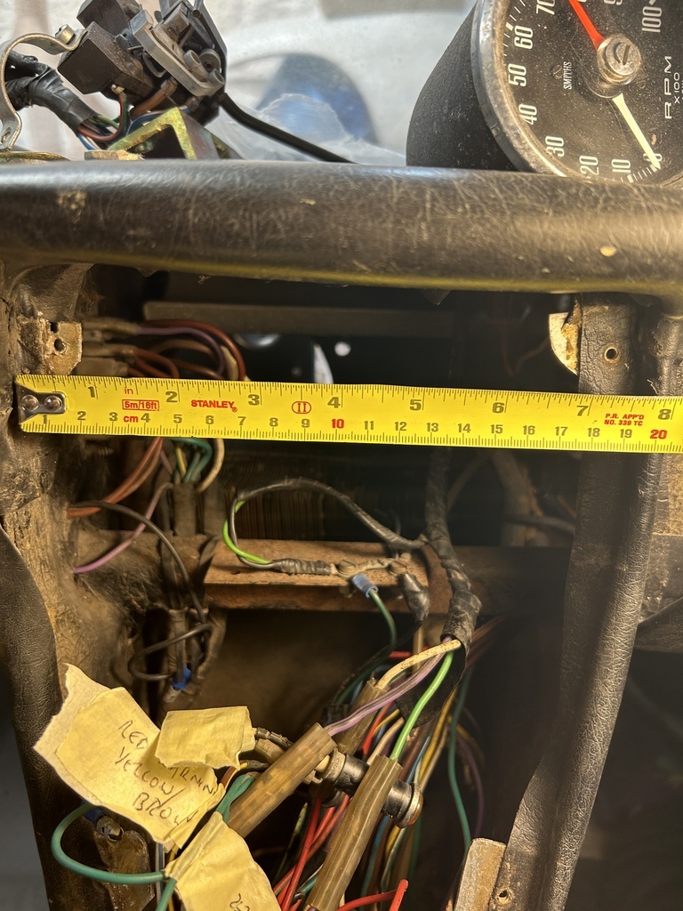 With that my attention has turned to the next, larger rewiring task around the FIA cutoff, ignition and starter switches, here's a pic of what was hiding behind the dash panel as found.... 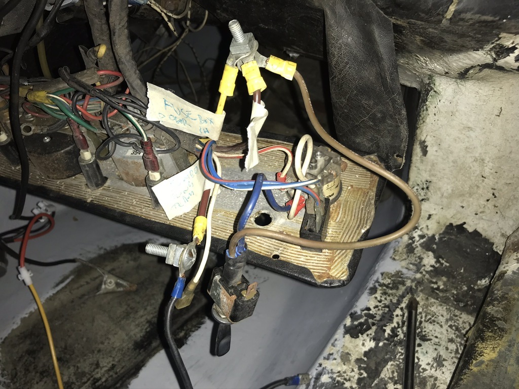 Thanks for checking in.. |
| |
Last Edit: Jun 19, 2023 21:29:02 GMT by 16grit
|
|
16grit
Part of things
 
Posts: 216
|
|
Jun 21, 2023 12:49:15 GMT
|
Managed a short session in the barn today. The idea was to push on with work to the FIA switch (which is mounted in the front luggage area), and the ignition and starter switches behind the steering wheel in the dash board section there. I'm waiting for some heavy duty crimps before I can carry on with the FIA battery connections, so I turned my attention to the ignition and starter areas, starting to sketch out with real cable the runs that I'm going to need. On the Suzuki G13B engine that I'm using, the starter and alternator are both on the inlet side under the injection plenum, with the engine's external water rail running above them, meaning space is tight tight tight. So you have to keep things neat neat neat right? Well, kindof.. More of this later when I look at starter positioning, but with my project running a FORD bellhousing pattern and the starter hung off my own adapter, things are also a little more complicated than with an original engine In addition to the heavy positive feed to the starter motor, I need a push-button to starter cable, a relatively large starter to alternator connection and the two smaller wires for the alternator, one running to the ignition switch and another from the fusebox via an ignition warning lamp and diode to the alternator. Here's my very Denso-like 50A alternator that has seen better days but is being wired in as needs must. 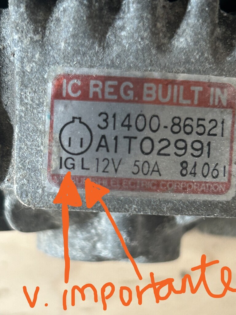 As you can see from the photo, there's the connection point for my 'IG(nition)' and 'L(ight)' wires explained to me in broad daylight on the alternator case itself with a trick little silver backed infografik, silver-backed I say! I was going to need a connector to fit into the alternator, fotunately these pre-wired Denso types are available all over the webs.. 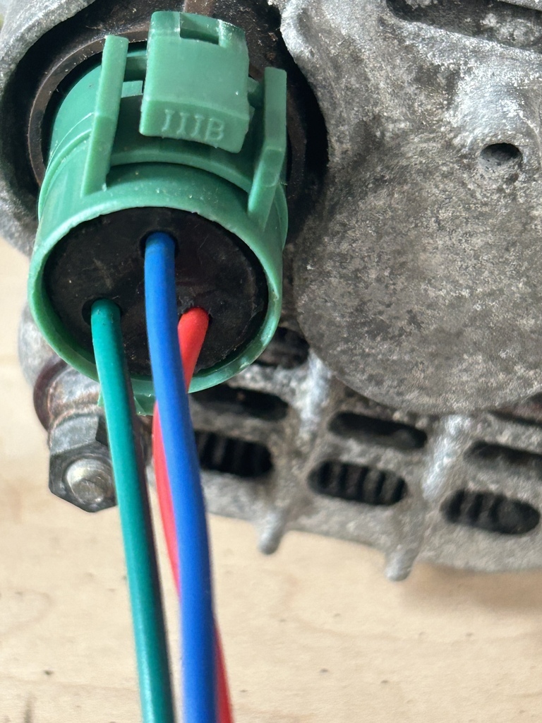 I had a rummage around and found a couple of pieces of cable long enough to run from the dash area to the extreme rear of the car where the alternator resides, and loosely tucked these into place without yet connecting them up to the connector pigtail shown in the photo above. It seems that my alternator is like a few Densos that only use two of the three available terminals on the back of the alternator, so one of those will remain unused in my application. While I was poking wires from the front the rear of the car I found a another piece of oh-my-god-have-you-see-the-size-of-it-but-oh-yes-it-will-have-to-do stripy green and yellow wire that volunteered to play the role of my starter starter from the push button (starter). Here's the big green snake up at the dash area close to the starter switch 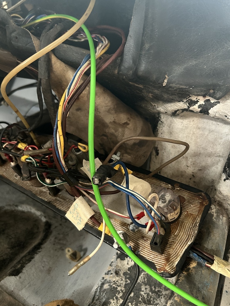 Before joining its two smaller mates heading for the alternator 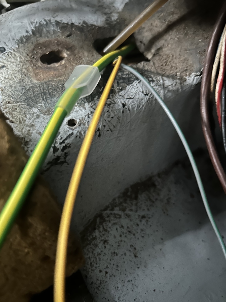 So here's the two alternator wires laid in place pending crimping, next to the big dadd-e-o main starter feed, but no green, as they say.
No it was at this point, looking at the back of the starter motor and seeing a neat little bespoke female connector point on the alternator itself, I thought I had better look for the starter box and see if I could find anything. This is what I found 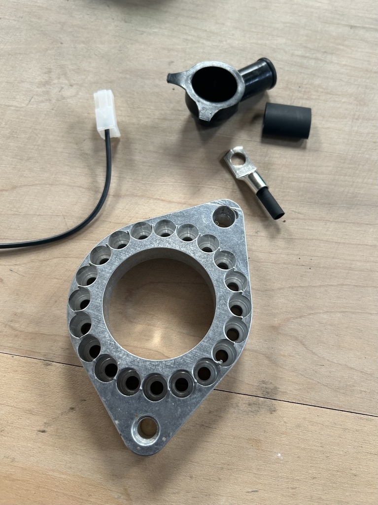 Cool little pigtail thingy for the connector, cool. But what about the big alloy thing? 
I remembered that entire engine/gearbox adapter plate as currently fitted to the car was only 'Prototype 3' and that 'Prototype 4' had never been fitted. Here's the plate version on the car now 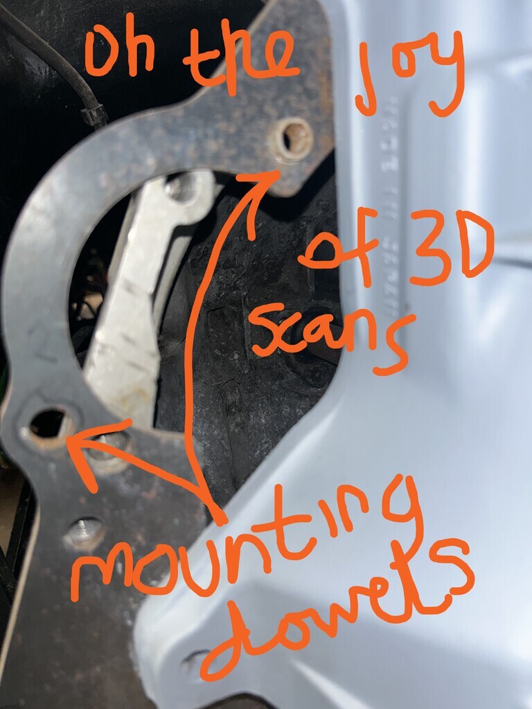 Except, the starter I ordered, as you can see from this photo, has threaded mount holes, so was never going to work and be removable from outside the bellhousing like that, was it!!?? So much for all that ten-of-a-thou-scanning-accuracy-if-you-take-your-eye-off-the-ball 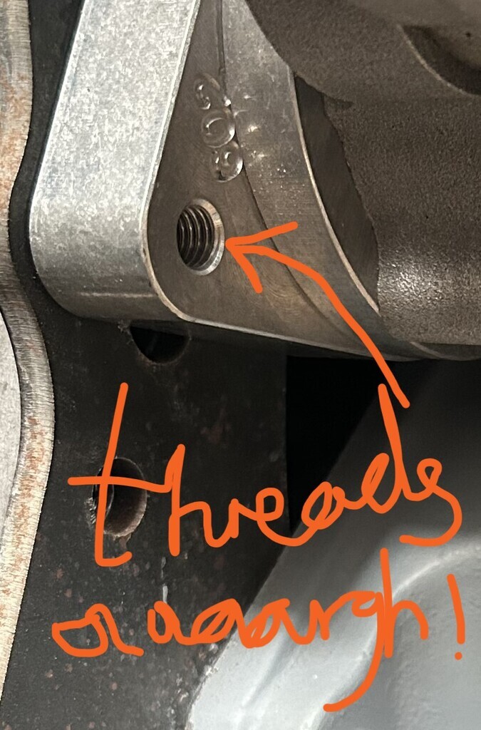 And that's why I had had this adapter cut (I wonder how long ago that was by the rust on I hear you say??): 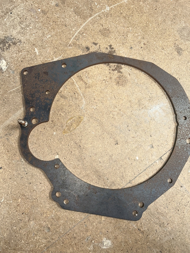 Which has been redesigned to have the starter attached to the adapter plate using two studs and cunningly dimensioned spacers that will do the job of the dowels and mount into a new starter nose....... which is what I had found in the bag... 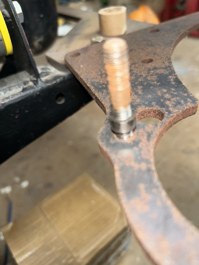 Having lost one or both of the studs and one or both of the expertly crafted spacers, I decided to see if I could fit the big snakey green cable into the neat little connector that WOSP had so kindly supplied.... (probably just a little bit of crimpig therapy, which I didn't even know was a thing I needed until today) First wheedle out the old oh-so-tiny-cable 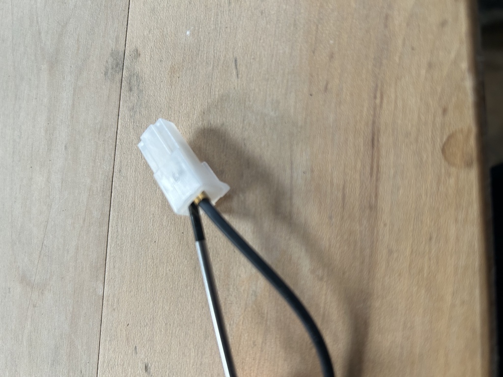 Yay, on a roll now... 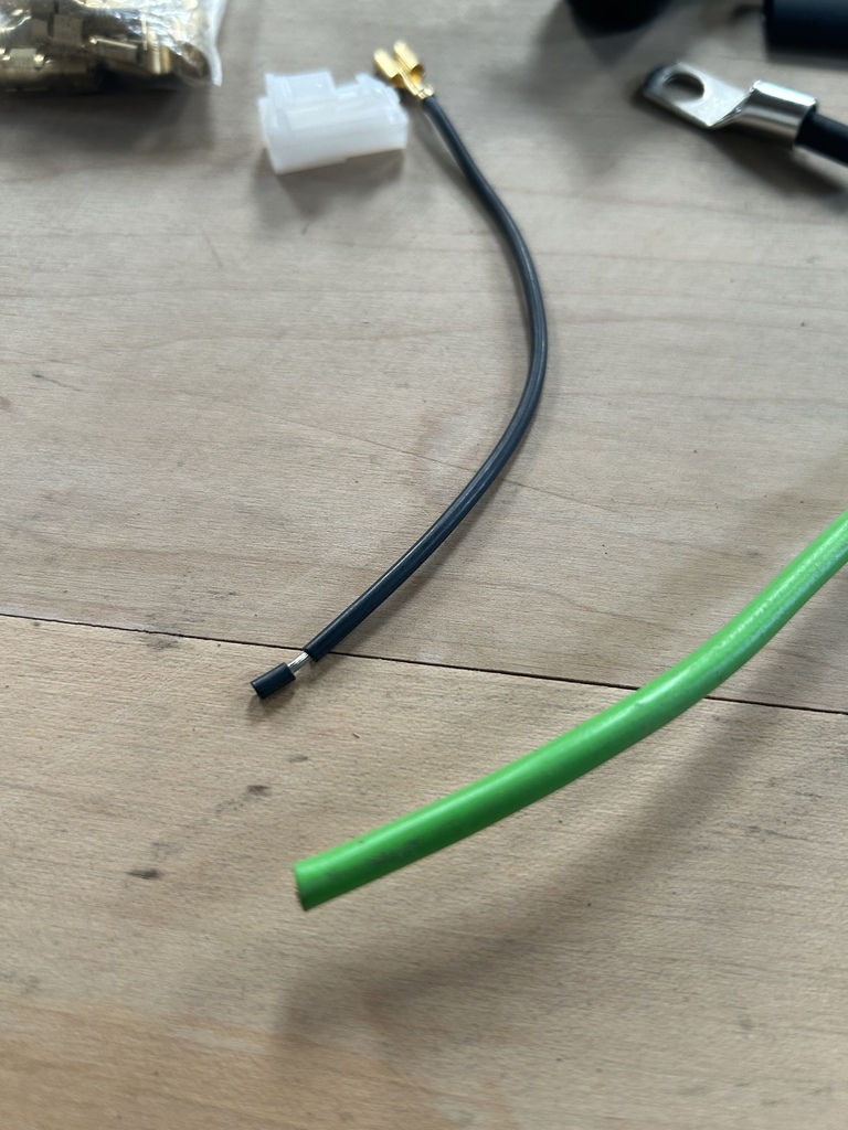 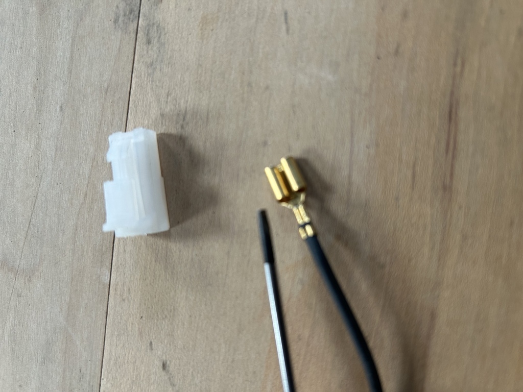 Found I had a chunky 6.3mm spade to take giantsnake wire.. 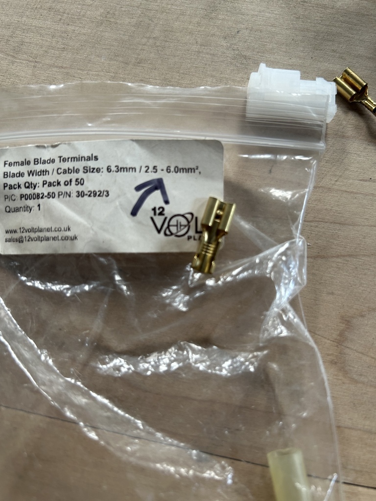 Obligatory Crimp Photo!! 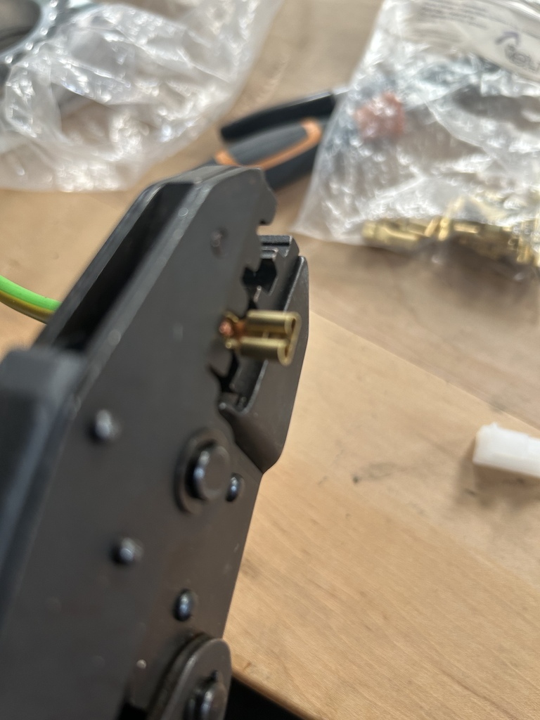 Success 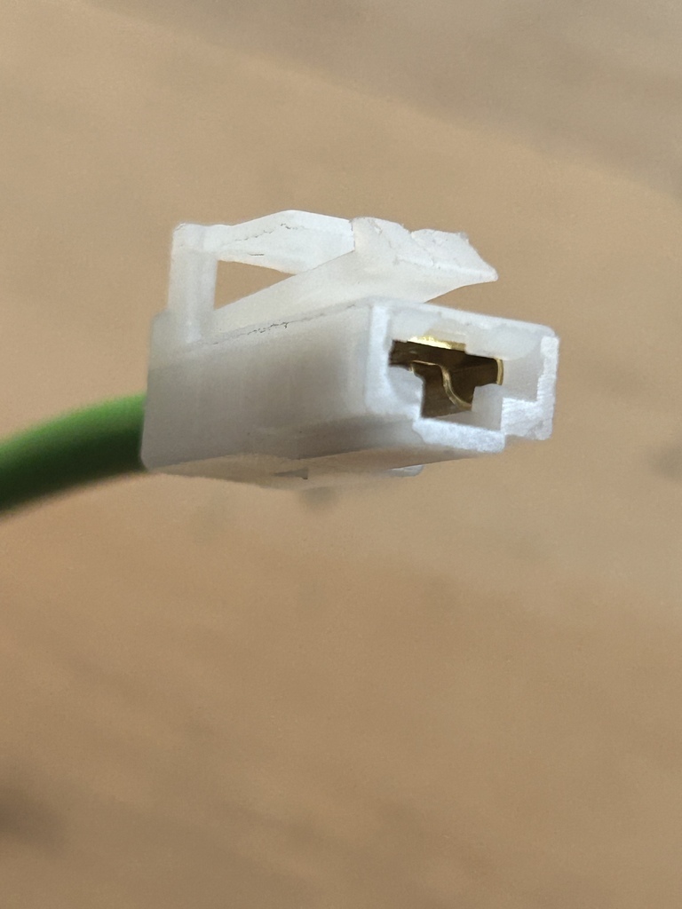 That end done 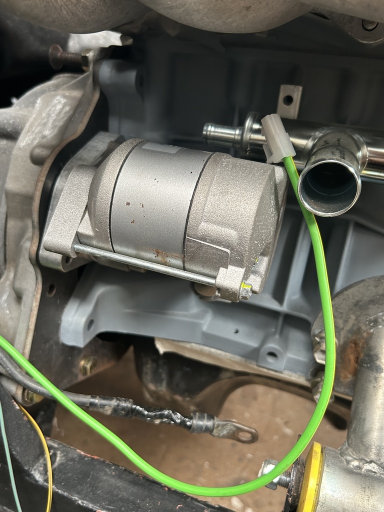 So now I have to turn my attention to finishing the work on the new replacement adapter plate, finding the lost studs etc, tapping the holes properly and cleaning the thing up... Tune in for more crimping next time, thanks for taking a look, |
| |
Last Edit: Jun 21, 2023 12:54:59 GMT by 16grit
|
|
|
|




 ..it was obviously time to
