Enbloc
Part of things
 
Posts: 399
|
|
|
|
To continue this rather long tangent… The scuffed bores in the block were salvageable with a hone and cam also and that was about it from the short block. 😕 Where do you find a complete rotating assembly for a mid 50’s Caddy engine? You dig deep into the memory banks of a vague recollection of a for sale ad that may have had what you needed. A quick search and find said advert from 3 years previous and it’s all still available. Result! Beggars can’t be choosers and even though the replacement crank was more than usable the locating dowel hole in the crank flange had been gacked by I assume someone in the past attempting to drill it out (why?) instead of just knocking it out from the back. Managed to save it by using the flex plate adapter as a guide to enlarge the oval hole and then turn a stepped dowel back to standard size. 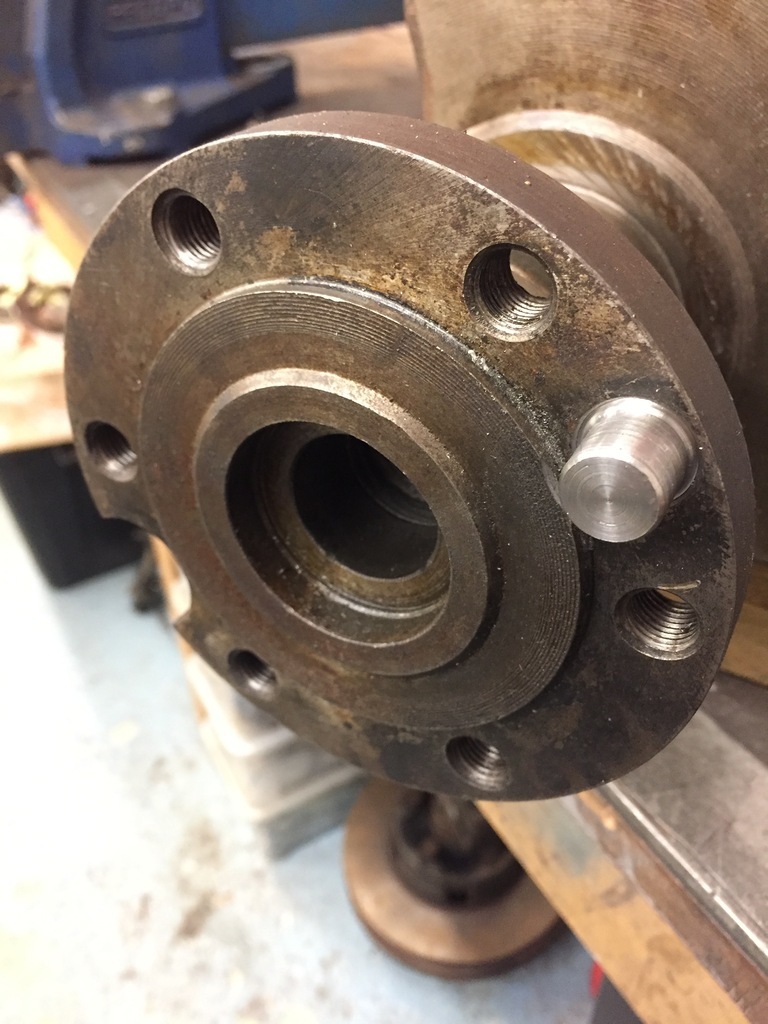 On to the oil pump. Suspicion was starting to rise at this point with the oiling system having issues and being the cause of the failure especially as the oiling system is seen as a weak point on this engine family. The stock oil pump is this thing. 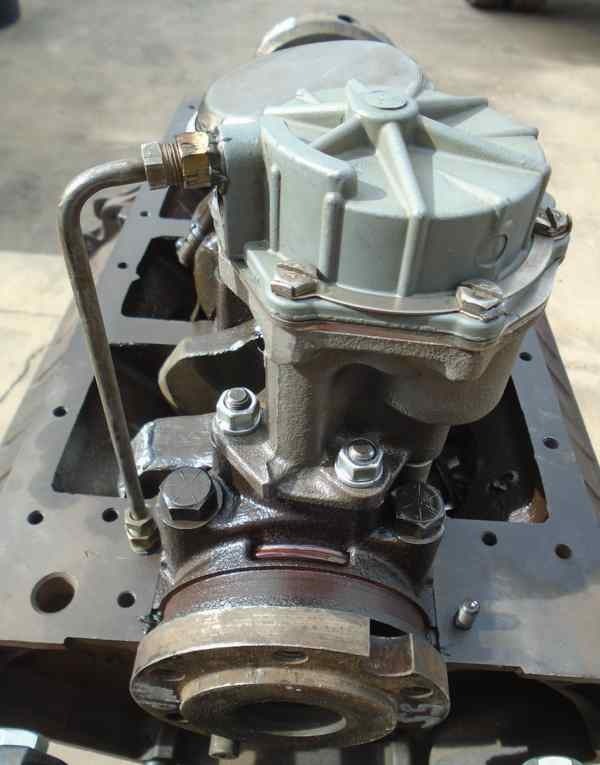 What’s going on here is a conventional oil pump with a secondary vane pump piggy backed on. The secondary pump is a vacuum pump. It’s only job is supply vacuum to the windscreen wipers! The crazy situation is the two pumps are linked internally so when the vacuum side starts going wonky, as it surely will, the oil pump starts pumping air not oil. 🤦♂️ Strike 1. Luckily Cadillac saw the error of their ways and in 1959 there was a cross over of oil pumps which meant you have an early style pump without the vacuum side that retro fits into the earlier block. Another small issue found. There should be a felt seal from pump pickup to pump inlet. If it’s missing it can again, suck air. It was missing. Strike 2. 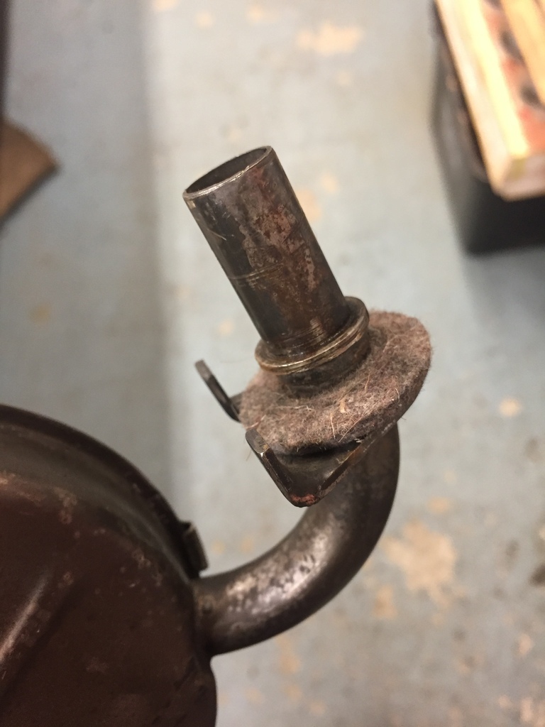 The short block had all the oil way core plugs knocked out for cleaning and drilled and tapped for threaded plugs and of course new pistons and bearings and ARP hardware for good measure. Short block went together and the cam degreed perfect which made a nice change. 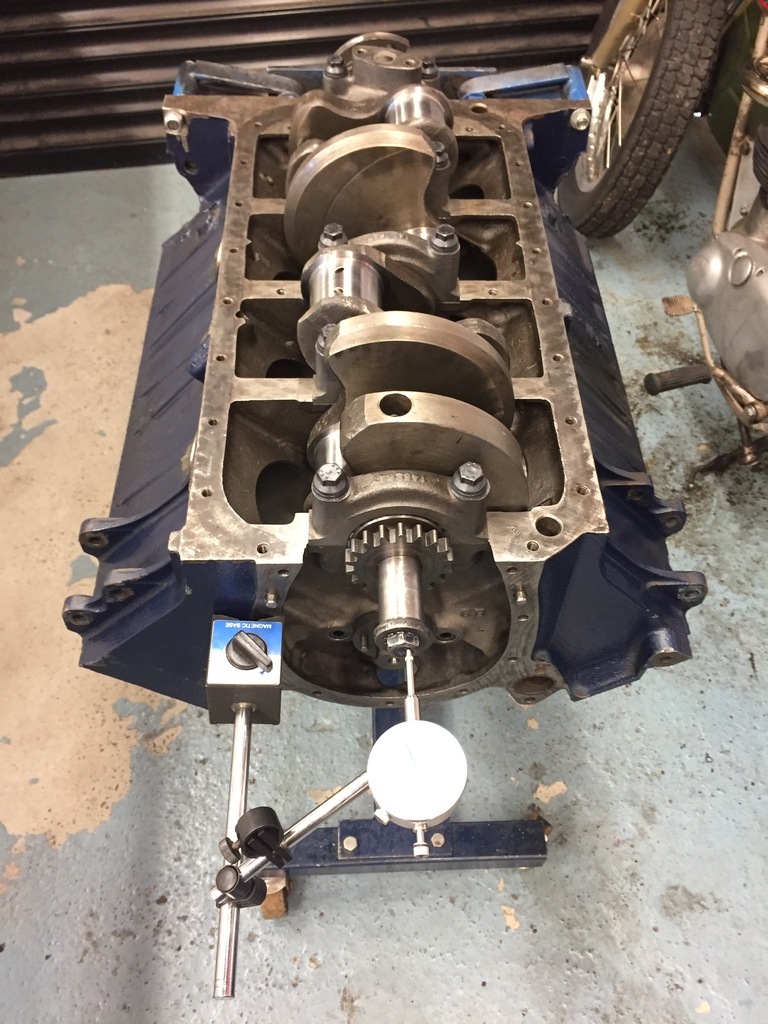 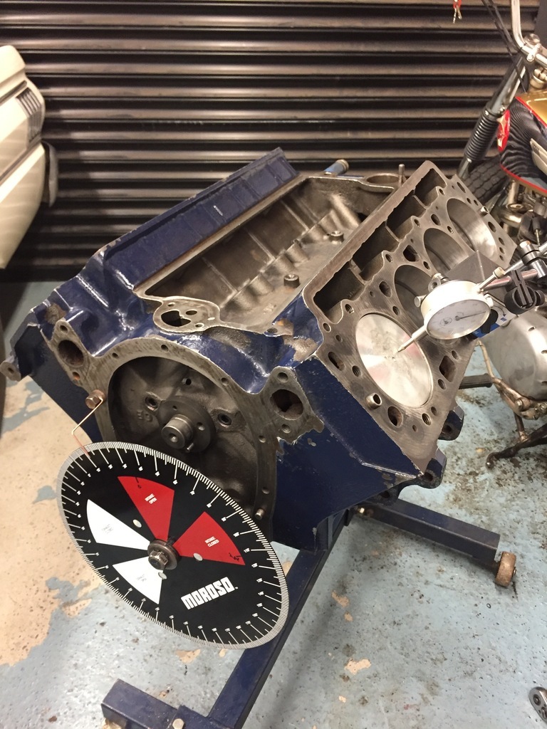 |
| |
Last Edit: Apr 6, 2022 22:59:39 GMT by Enbloc
|
|
|
|
Enbloc
Part of things
 
Posts: 399
|
|
|
|
Moving onto the heads. The heads had some new SS valves and valve springs thrown at them at some point. Problem was the valve seats were tired, the valve guides were worn and the valve springs were missing their internal dampers as they didn’t work with the OE spring retainers. With the heads stripped of course they got the ports cleaned up and port matched. 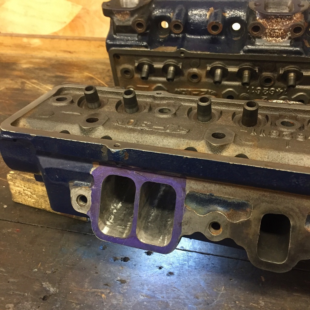 The OE spring retainers had this metal umbrella arrangement that acted as a basic valve guide seal or oil deflector. This is primitive stuff, doesn’t work very well and as already mentioned created issues with the replacement valve springs. I couldn’t see a reason why their removal wouldn’t be an issue, so off they came. I initially tried to face them off in the lathe but the umbrella portion was so thin they just collapsed in the chuck. The angry wheel then made short work removing them but it took some time carefully grinding them flat and to within a couple of thou of each in width. 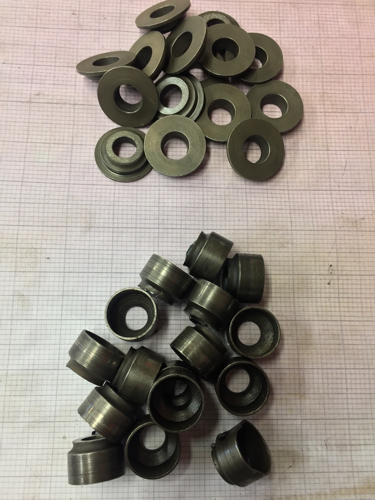 The springs could now be mocked up and measured for height. They were all with in 0.010” of each other which is good going and shows these engines were built to tight tolerances from the factory. 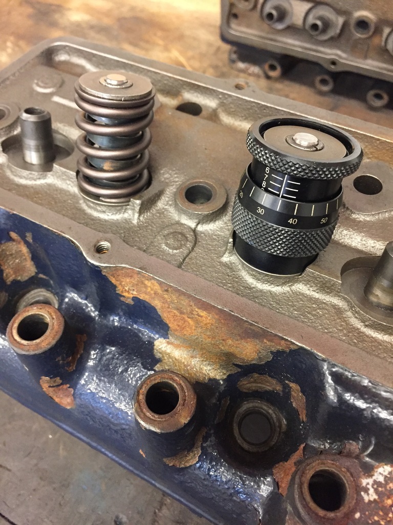 A valve guide seal was now needed and luckily the guides were the right diameter for a SBC/SBF modern style Viton seal to slide right on… but… the extra height of the seal on the guide meant there was naff all valve lift before the retainer ran into seal. The valve guides are quite long from standard so it wasn’t a problem to remove the 0.250” (1/4”) needed to give enough clearance for the valve lift. 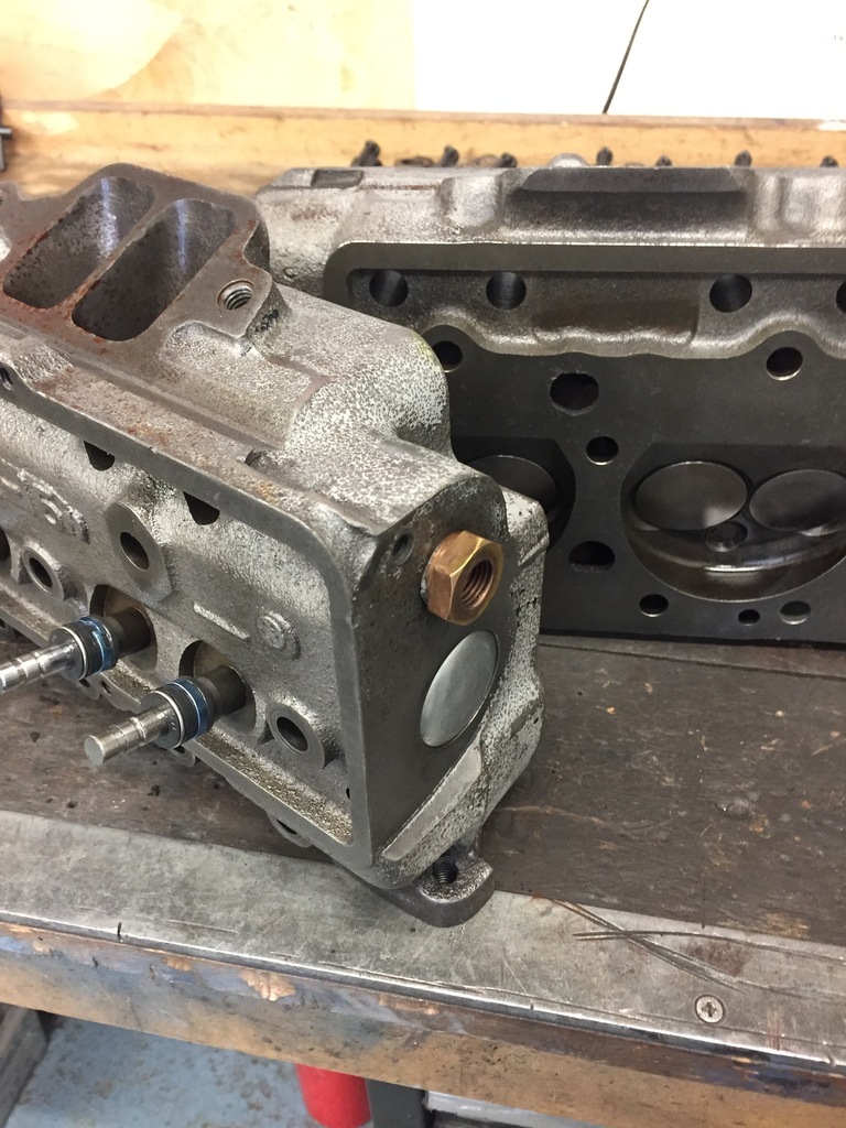 The heads were sent off to the machine shop to get new seats, valve guide liners and the guides machined down for the seals. The rest of the valvetrain was a bit of a mess. The valvetrain is non-adjustable which is fairly common for US V8’s. This is fine if you’re using all stock components, but change one thing, in this case the cam, and the whole valvetrain geometry goes to curse word. First job was to find some adjustable rocker arms. They were available in period but are now rare. Rockers from other engines of the period like Studebaker apparently fit and are adjustable but it’s all hearsay and rumour and again hard to find. Then I was put onto a company called Harland & Sharp in the US who apparently still made them. I rang them, they would make them to order and would be with me in 4-5 weeks. Yay. 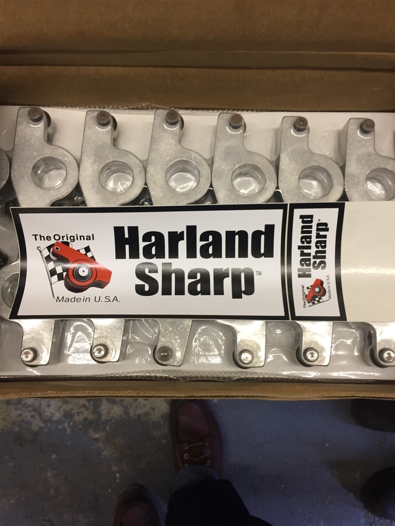 On stripping the rocker assemblies more issues were found. Two stands were cracked which I managed to get replacements for and the rocker shafts were worn probably due to the various sludged up oil holes. Got the new parts and went to assemble and found another cracked stand and a mis-matched stand in the set as well because there are 3 different styles and one must have been changed out before in the distant past. Annoyed that I had been halted on the assembly for the second time I bought another pair of used assemblies so I wouldn’t be caught out again with a lack of spares! So, 48 rockers, 16 rocker stands and 6 shafts later I finally had two usable rocker assemblies. 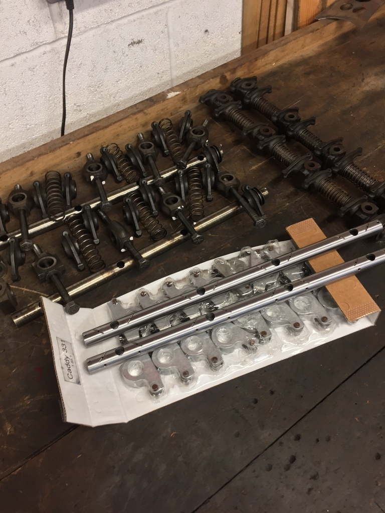 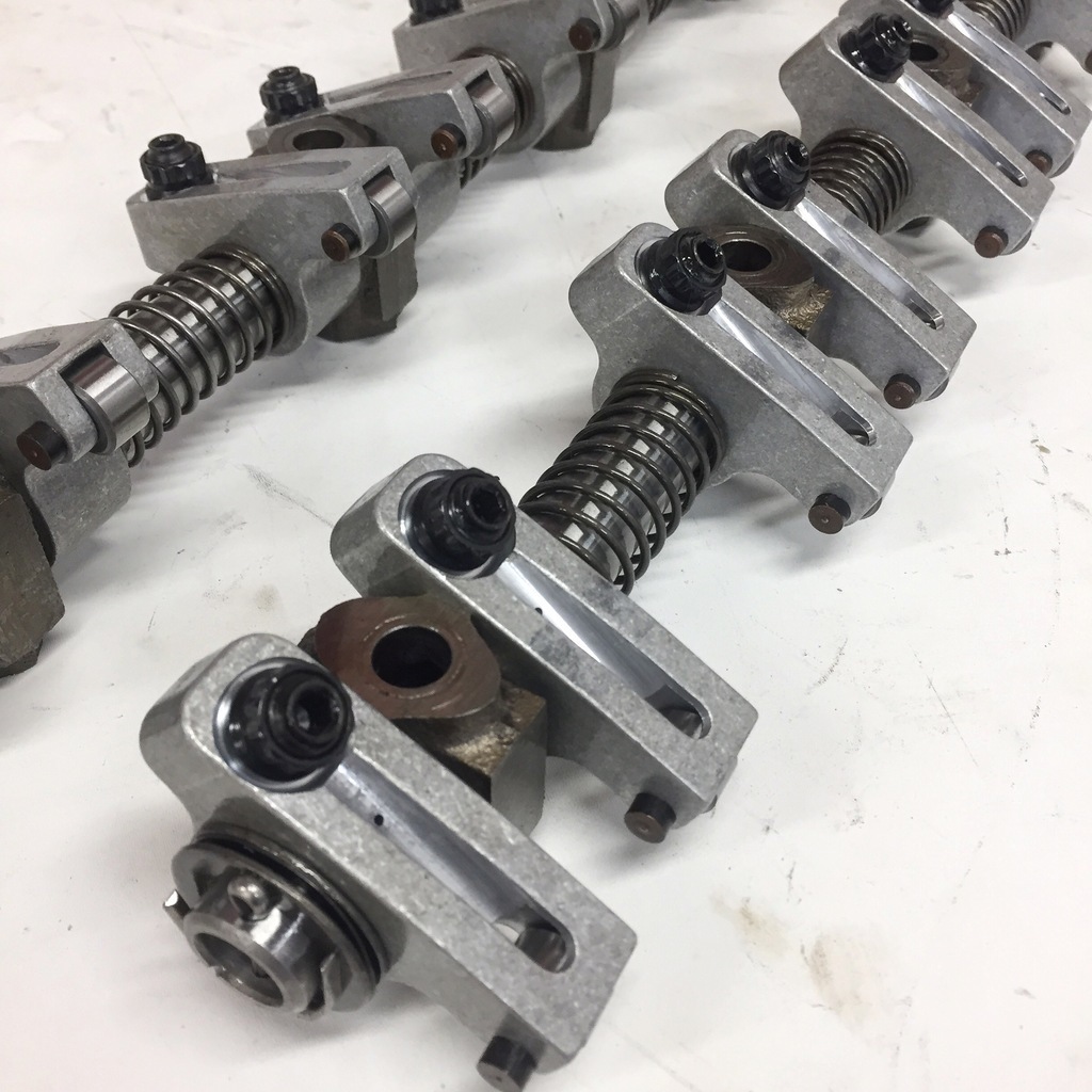 |
| |
Last Edit: Apr 11, 2022 2:15:12 GMT by Enbloc
|
|
Enbloc
Part of things
 
Posts: 399
|
|
Apr 12, 2022 23:38:45 GMT
|
With the heads assembled and mocked up on the block it was onto measuring the push rod length and setting the rocker sweep across the valve tip. These engines have a long push rod at nearly 8 1/2” long. The longest adjustable push rod available for setting up is is just over 8 1/2”. Lucky. 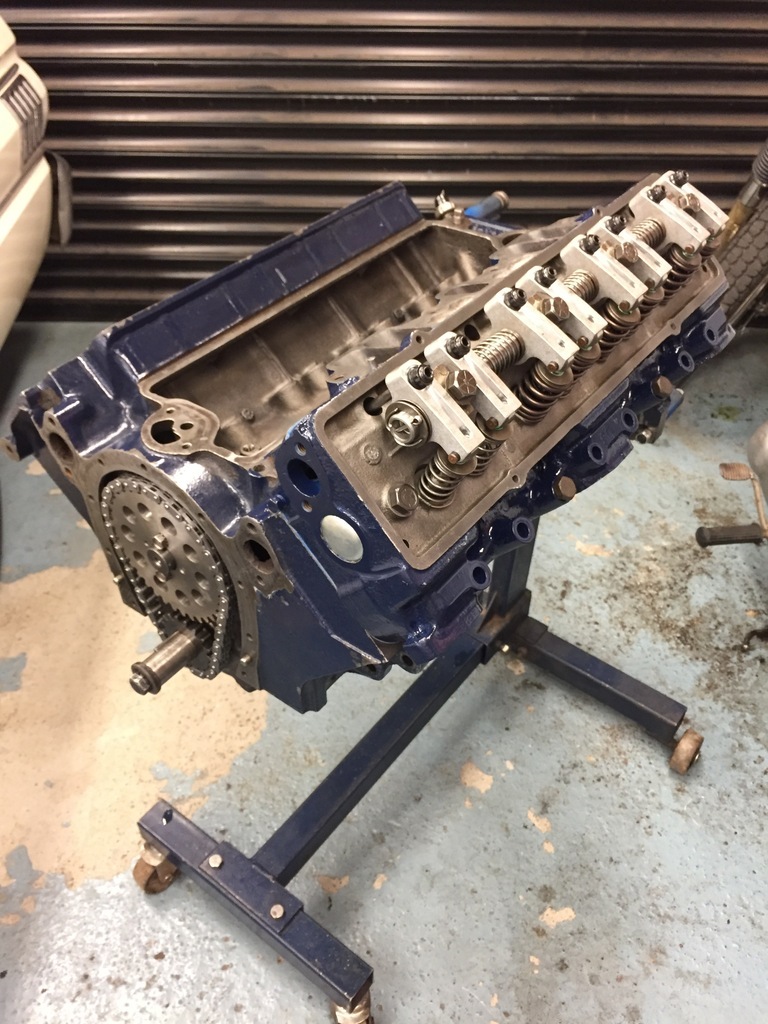 Then things didn’t quite go to the plan. What I’m trying to achieve is the optimum movement of the rocker roller across the tip of the valve. The reasons for this are to achieve the least amount of lost motion and to locate the movement as close to centre as possible to stop excessive side loads on the valve stem which prematurely wears the valve guides. In extreme cases it’s even possible to roll the rocker right off the edge of the valve tip. To test you simply engineer blue the valve tip and cycle the valvetrain a couple of times and then inspect and measure the sweep that shows in the blue. What you want is a central sweep that is no more than 0.050” in width. 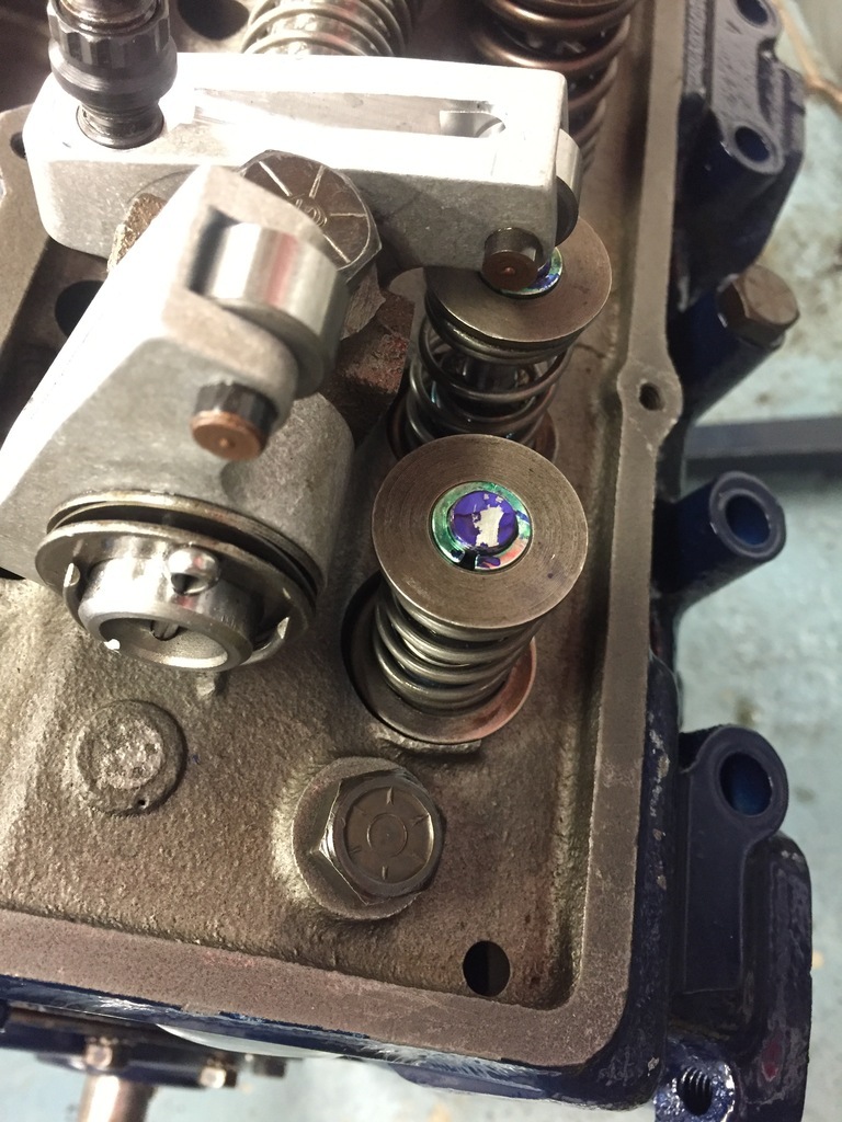 This is the best I could get no matter what I did. Off centre and around 0.100” width. I changed the pushrod length changed +/-. I tried shimming the rocker stands up. I even made caps for the valve stems out of shim stock to change the valve length to no avail. It seemed to me that there was a fundamental design issue going on and that the real problem was that the whole rocker assembly was in the wrong place i.e it needed shoving back. Myth and lore with these engines is they have a habit of breaking rocker shafts in high stress (racing) applications. I can believe it after going through this. Its not unknown to slot mounting holes in rocker assemblies to be able move stuff around but that was a no go with this as the rocker assemblies are bolted down and oiled via the head bolts. Slotting the stands would lose oiling to the rockers and create a pressure loss in the oil system. What to do? Nothing! It is what is. It’s not a race engine. It’s going in a road car with a slush box. It might not be great but it’s not terrible either. Sometimes you just have to accept and move on and it’s probably better now than it’s ever been. On to the finishing touches. The engine comes with a rudimentary sump baffle that bolts to the block. I simply added some extra baffles to contain the forward and back movement of oil. Also made a new dipstick tube to replace the broken, bodged up one that was on it. 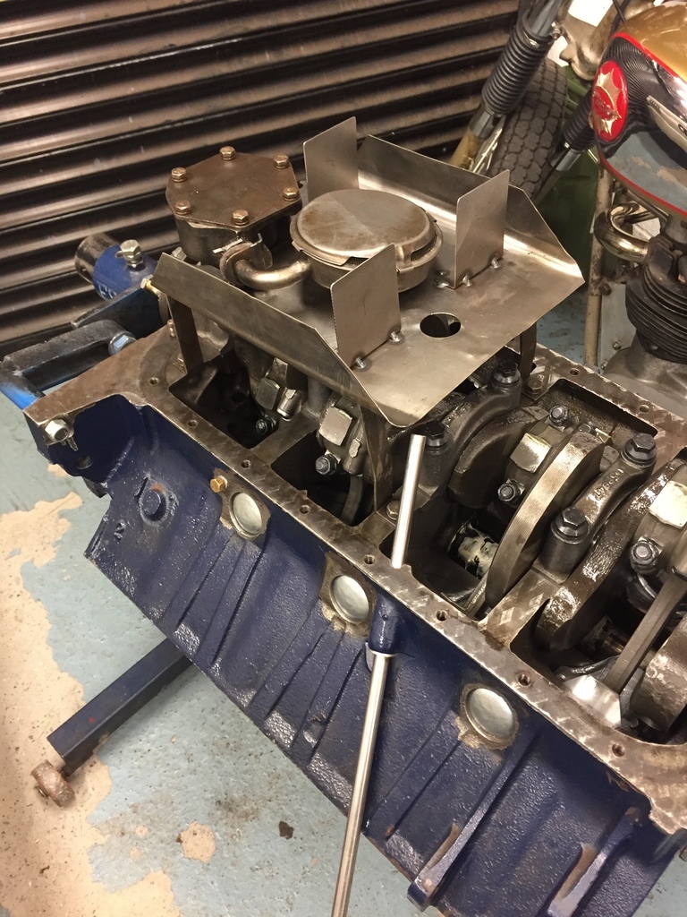 An oil filter wasn’t standard but you could have a bolt-on bypass filter fitted by the Dealer. This engine had the filter fitted but the oil lines were a mess with most of the fittings rounded off. 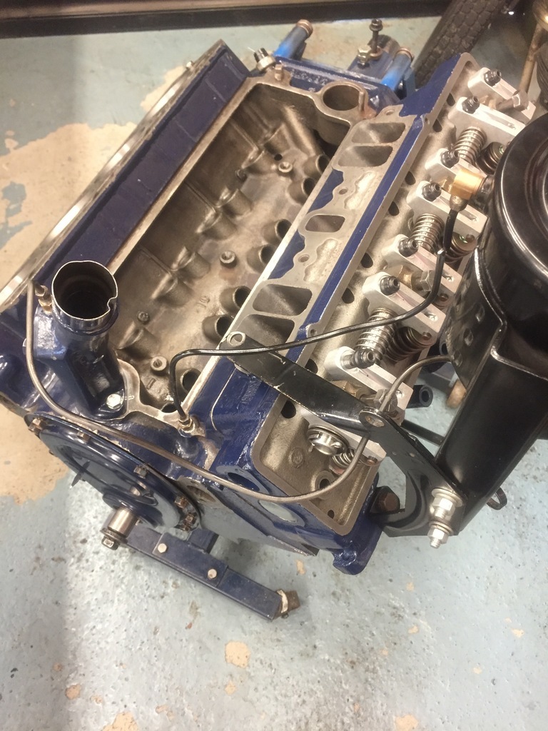 I couldn’t live with this so I replaced the fittings and remade the lines. 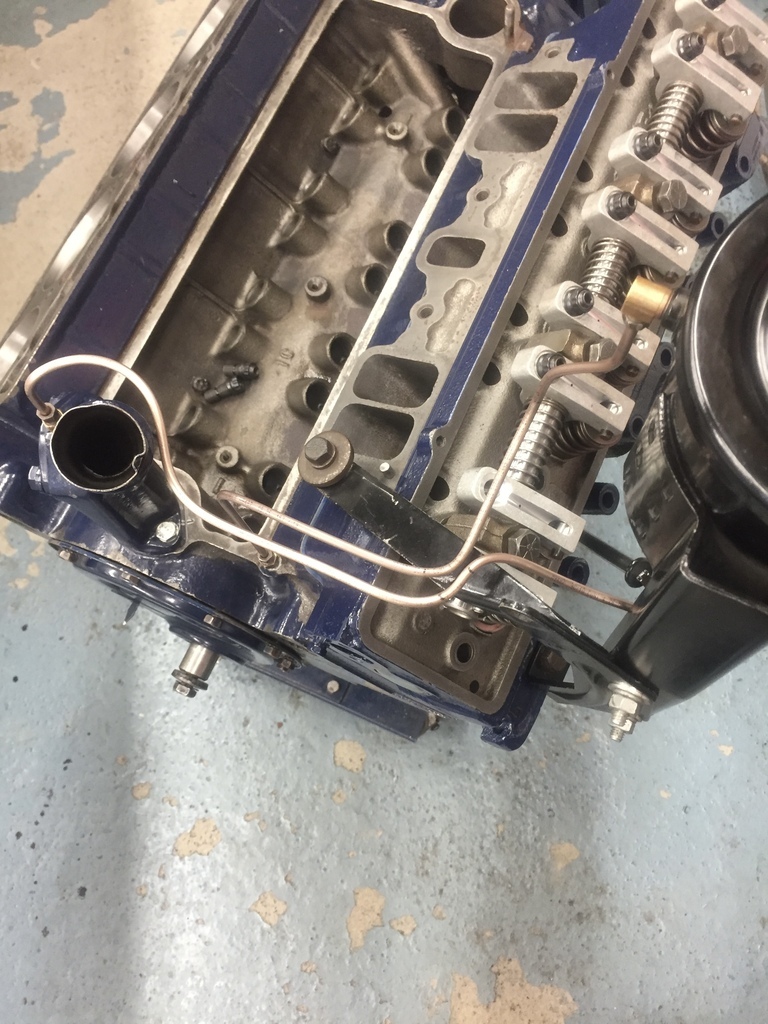 Converted the road draft breather system (rubbish) to PCV instead. 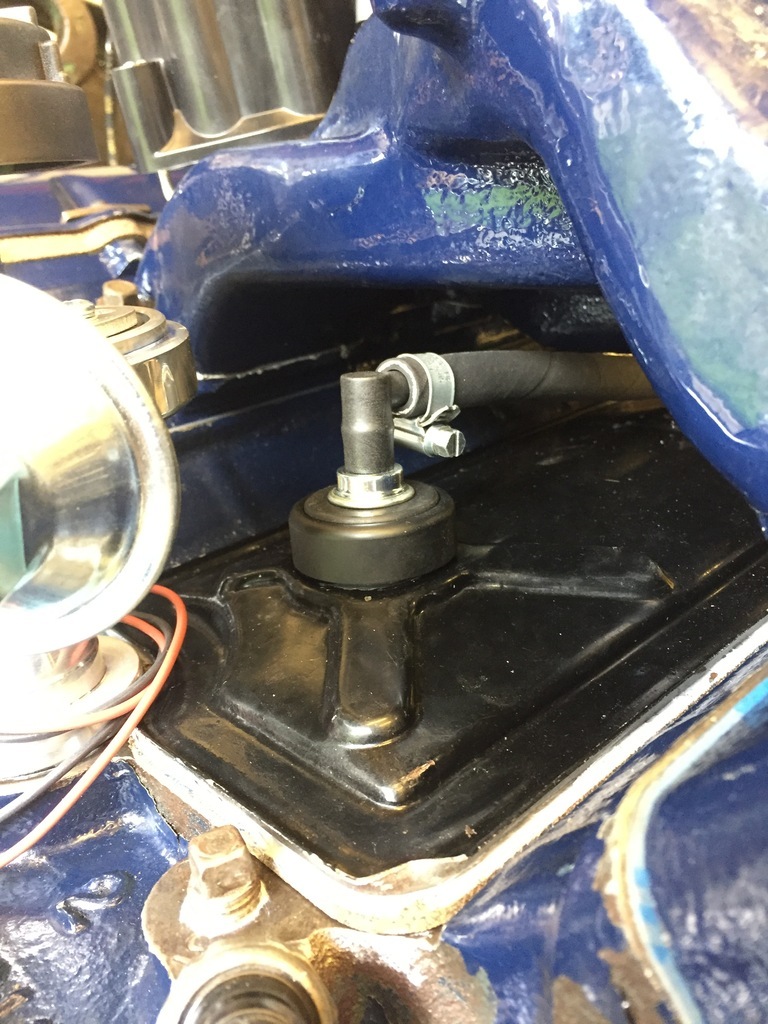 The original dizzy got canned and a brand new Pertronix billet one with igniter II and fully adjustable ignition got fitted instead. But before it went in I changed the stops and advance springs from the short, lazy curve that aftermarket dizzy’s always seem to evidently come with. 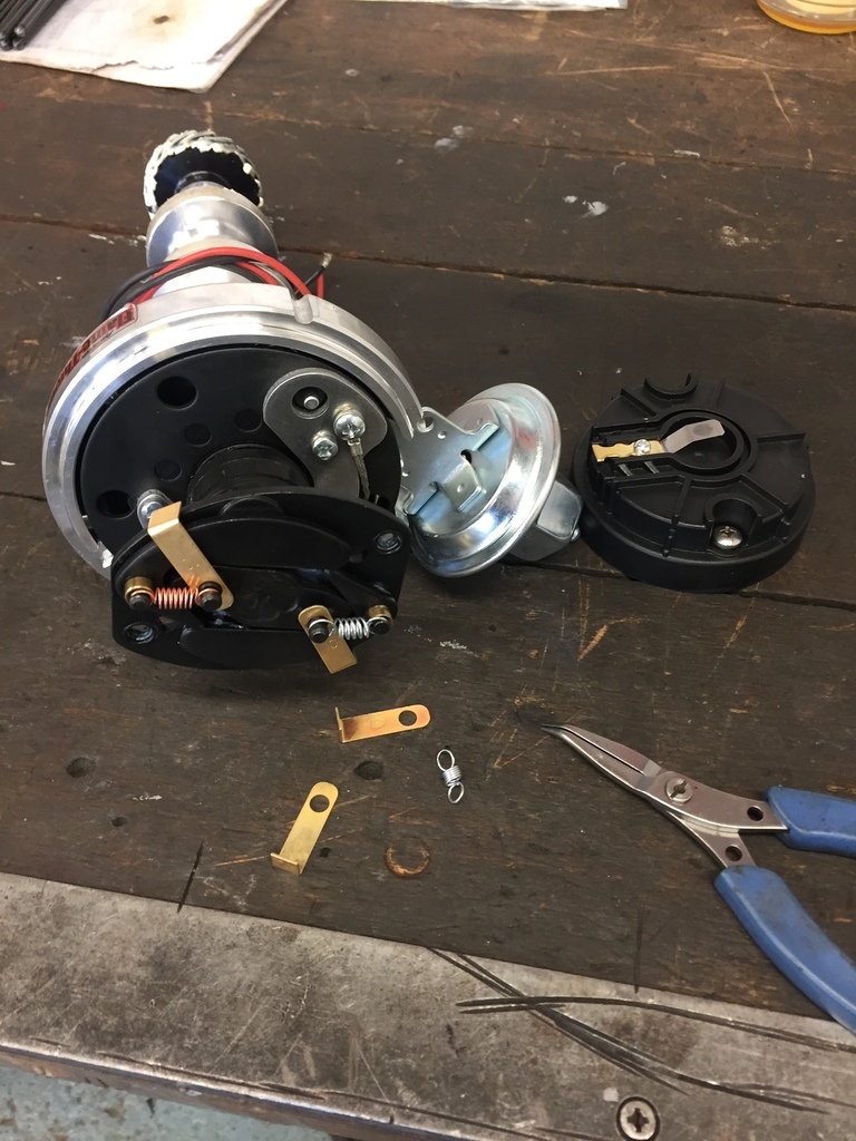 One final job before first start was to make a oil priming tool as funny enough they’re not available for these engines. After having this engine so long I was determined for it go back in and be started. 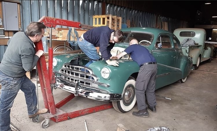 We blitzed it one Saturday and done… |
| |
Last Edit: Apr 12, 2022 23:46:01 GMT by Enbloc
|
|
misteralz
Posted a lot
   I may drive a Volkswagen, but I'm scene tax exempt!
Posts: 2,500
|
|
Apr 13, 2022 12:49:42 GMT
|
|
I don't have anything useful to add, but I am loving this thread. Is the Caddy motor the same as the one used in the Riva Aquarama? Because they are LUSH sounding things!
|
| |
|
|
Enbloc
Part of things
 
Posts: 399
|
|
Apr 13, 2022 15:37:40 GMT
|
I don't have anything useful to add, but I am loving this thread. Is the Caddy motor the same as the one used in the Riva Aquarama? Because they are LUSH sounding things! Thanks! I had to look that one up. The Aquarama didn't come out to '62, so no it wouldn't have been this engine as '55 was the last year. It did live on with capacity increases into the early 60's though. I would think you could have specified any engine you wanted from Riva if you was buying new but Riva seem to have their own design V8. 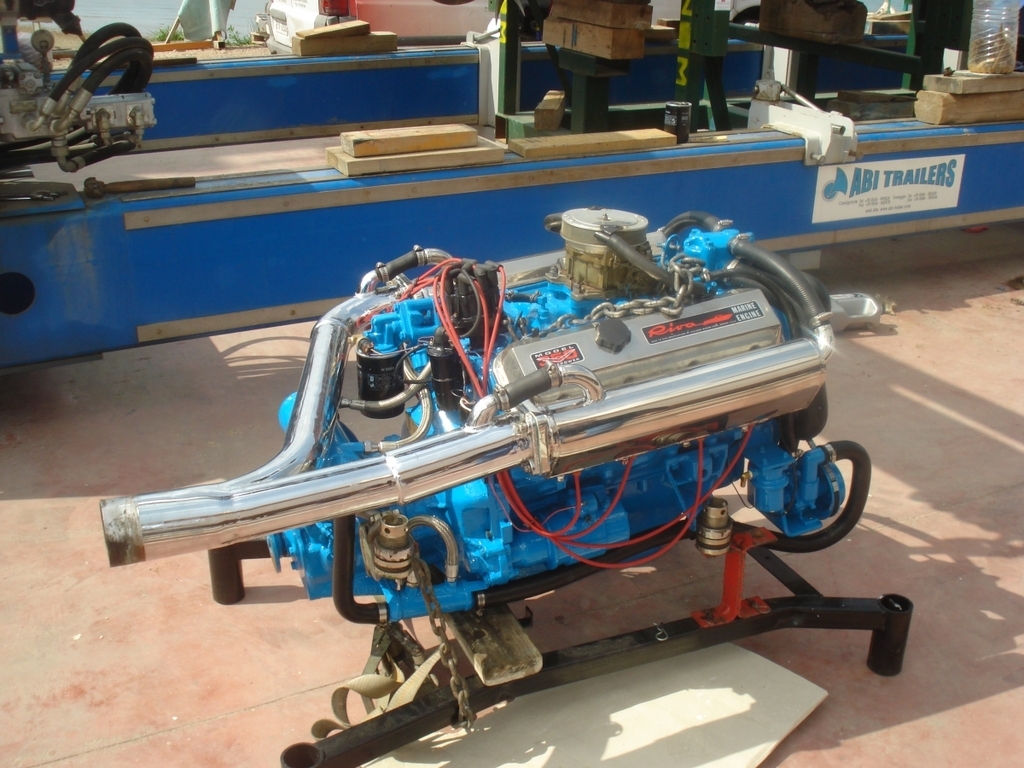 |
| |
Last Edit: Apr 13, 2022 15:46:26 GMT by Enbloc
|
|
Enbloc
Part of things
 
Posts: 399
|
|
Apr 25, 2022 22:28:52 GMT
|
After years of building NA motors I got a real hankering to build something with forced induction. The obvious choice would have been a roots style blower sitting atop with everything available to bolt one on and go but I’d been soaking up the turbo revolution for years and wanted some of that. Then I got to thinking about that built Flatty that I had abandoned under the workbench for over 2 yrs. Forged pistons, check. Billet rods, check. Strengthened bottom end, check. Add onto the fact that I knew I had to take it apart because it wasn’t assembled very well the first time meant it would be the perfect opportunity to open up the ring gaps for boost. Apart it came, which was a joy because it was clean and fresh and not the usual seized ball of oil and dirt. 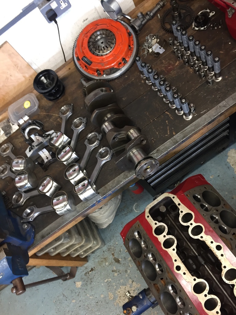 I found a few mistakes taking it apart, nothing major, just poor attention to detail generally. I was feeling better knowing it was worth the effort so far of taking it all to bits again and then when I had it back to a bare block I inspected the ports. I don’t know what I was doing the first time but what I did do was pathetic! I then spent multiple hours a day, for the next 2 weeks with a die grinder until I lost feeling in both my hands and/or soul. When all the dirty work was done and the oil gallery and core plugs removed I hit it with the jet wash for a thorough cleaning for re-assembly. With jet wash in hand I had a play blowing water down the inlet and exhaust ports and even though this has no scientific value what so ever it does give some interesting visuals and food for thought in other areas. And together it went. 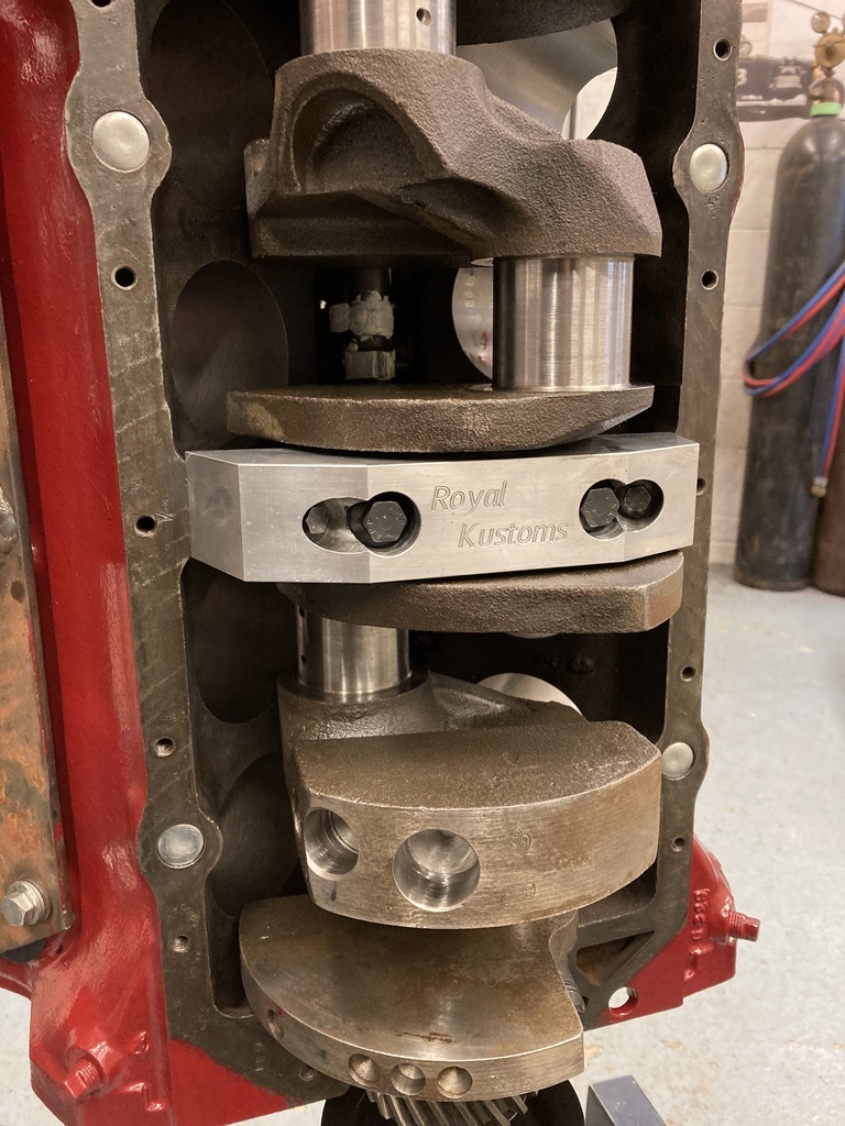 Back to the piston fitting fiasco, again. If you remember from previous ramblings the aftermarket connecting rods are to wide to fit down the bores so the piston/rods have to be separated, fitted separately and awkwardly assembled in the crank case. I wasn’t going through that again. 6 piston/rod assemblies would fit from the bottom (without rings) and the two middle ones wouldn’t because the piston skirt kissed the centre main webbing. Having a closer look at the interference it was so minimal. I reckon you could have tapped the piston past if you was so inclined. Out with die grinder and quick lick in the appropriate area had all the pistons able to drop in from the bottom for the first time. This then allowed me to assemble the piston/rods as normal, push the piston out the top of the bore enough to expose the ring lands, rings fitted in situ and the ring compressor used as normal to push it all back into the bore. Much easier. Obviously remembering that this all has to be done before the crank goes in otherwise a lot of anger and swearing will be expressed. 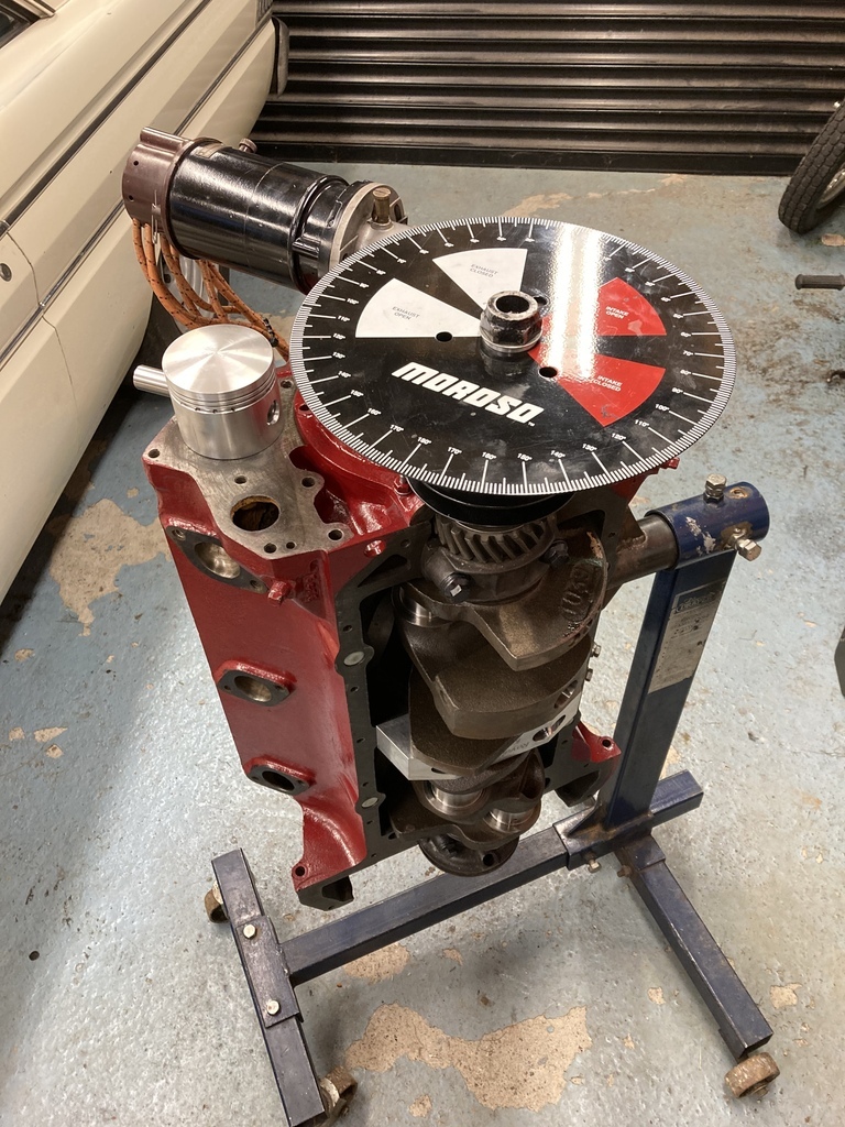 I needed a way to be able to rotate the crank with the degree wheel in place so I knocked up this adapter that bolts onto the crank flange using the factory flywheel bolts. 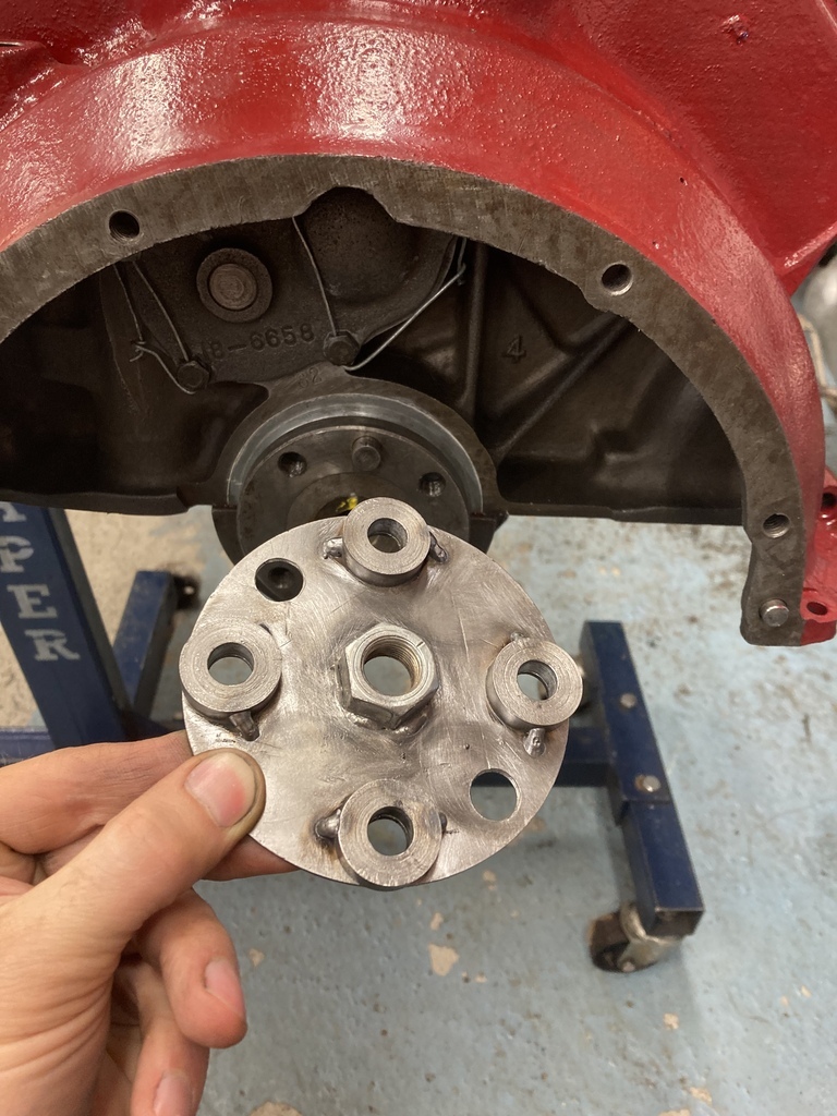 |
| |
Last Edit: Apr 25, 2022 22:38:51 GMT by Enbloc
|
|
jamesd1972
Club Retro Rides Member
Posts: 2,921  Club RR Member Number: 40
|
|
|
|
|
A turbo flathead?! just sounds do wrong and dirty if that makes any sense. Winner winner chicken dinner on a hot rod then.
Thanks for sharing.
James
|
| |
|
|
Enbloc
Part of things
 
Posts: 399
|
|
|
|
Flatheads from the factory have no external visual means of timing the engine. The original “crab style” dizzy can only go on one way and has a limited range of timing adjustment. Stock crab style distributor. 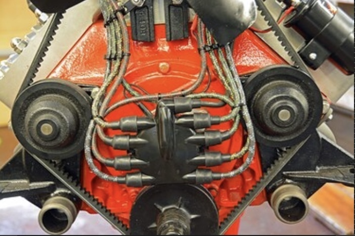 I’ve found a simple timing indicator with one of the front timing cover bolts. The centre of the bottom front cover fixing bolt head lines up perfect with the outer edge of the front pulley. I simply centre drill the bolt head for a short length of rod that has a sharp point ground onto it and then epoxy the ground point into the drilled bolt. After finding true TDC with the use of a dial indicator on no.1 cylinder, I simply mark the pulley where the point falls. To finish I usually cut a small slot in the pulley and fill with white paint. 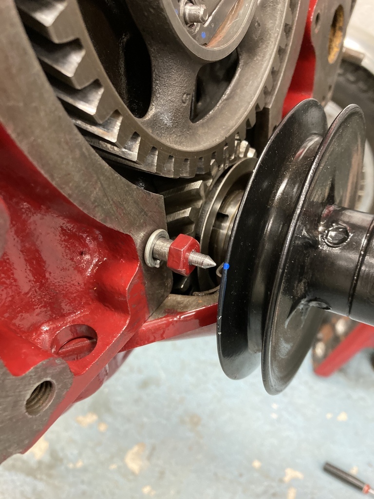 With True TDC found I can then move onto degreeing the cam. My cam degreed 5 degrees advance from the cam card spec. 1 or 2 degrees I can swallow but 5 is way out. Frustratingly, this is common scenario on aftermarket Flathead cams with no means of being able to adjust. If it was SBC/SBF there would 10 different ways to adjust and correct. What to do? One of the options on small block Chevys are offset cam dowel bushes. Sold as kits, easily available and relatively cheap I purchased a set. With the bushes in hand I took the original cam timing gear and drilled the googly hole bigger to except the dowel bush and the other three mounting holes got slotted on a rotary table. To finish, one of the original mounting bolts had the head removed and the shank turned down to effectively make a screw in dowel to fit the centre hole of the bush. Voila! I now have a fully adjustable cam gear simply by swapping out the offset bushes. 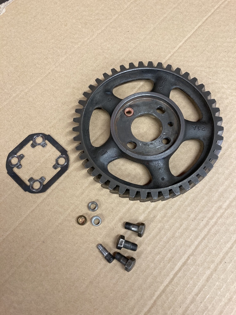 |
| |
Last Edit: Apr 27, 2022 3:06:31 GMT by Enbloc
|
|
Enbloc
Part of things
 
Posts: 399
|
|
Apr 30, 2022 19:54:14 GMT
|
The valvetrain was refitted from the previous build unaltered. The valve springs were fitted with an installed height of 1.900” which was in the middle of the Isky Cams recommendation. The first time round I used internal callipers to measure the spring height. Not terrible but not the most accurate either. You may of noticed in previous photos of a valve spring micrometer, which I had obtained since the first build. I tried the micrometer on the first valve and it was 0.060” over on what it should have been. The second 0.060”, the third 0.060” etc etc! Ok, they are all out but all out by the same amount. This is well within shimming so I ordered 32 0.030” shims. Remember the 3/8” spring spacers? Yep, the shims didn’t fit over the shoulder of the spacer. Some time later… 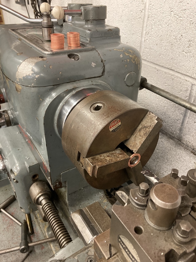 That brings things full circle. Next step, turbo. Where do I even start? No knowledge of turbo sizing, no experience from others, can’t read boost maps. What I did know was I wanted to start with cheap Chinese turbo. I didn’t want to throw a load of money at a genuine Garret or other for something that might never see the of day at this point. At around this time Richard Holdener posted a video on YouTube where he fitted a Chinese GT3582 Garret copy on a 3.0 V6 and was very complimentary to the sizing/combo. At a guess I’d say 3.0 V6 is probably fairly well matched to a 3.9 sidevalve V8 in breathing capacity and power output. There we are, £145 of your finest EBay Wuhan Whirly Boi. 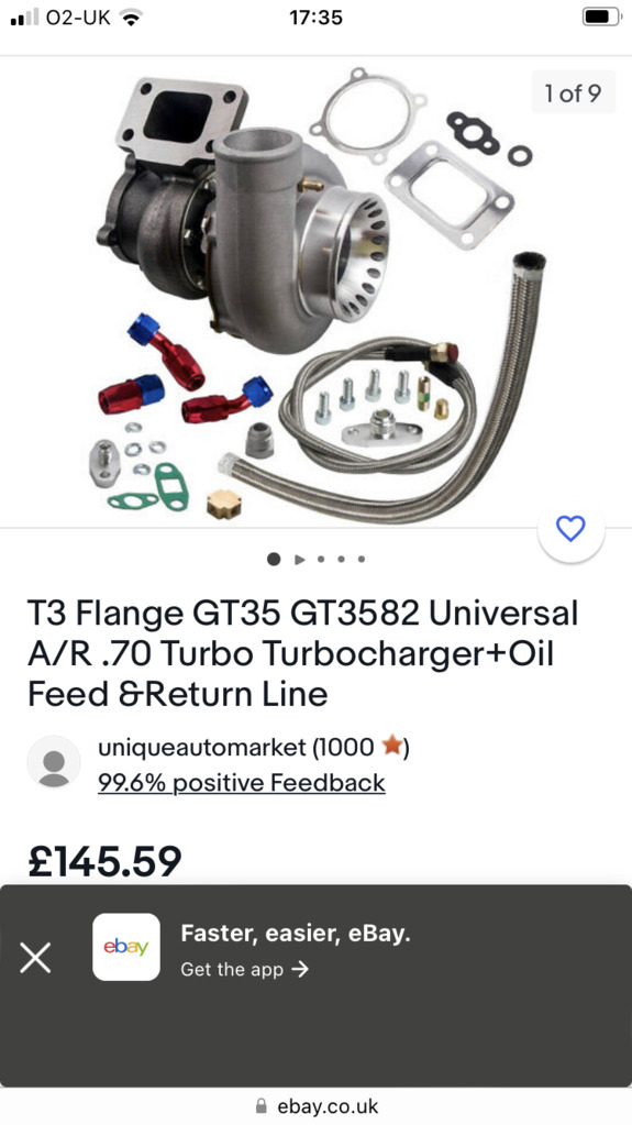 Moving onto the inlet. I had in stock a factory inlet that had been modified for a Weber 38 and a near new Weber 38 jetted for a Flathead. Initial thoughts were for a blow thru set-up that must have been done a X100 with a Weber so the info must already be out there, right? The whole Weber thing came about sometime ago when I was competing regularly on the hills with the Class Z Flatheads. I had the standard dual Stromberg 97’s which were fine but wanted more. The brief was, - Replace the complexity of dual carbs with a single, large cfm carb. - Move away from the basic 1930’s technology carburettors to a more modern, more tunable carb. - Gain MPG with a single, more sophisticated carburettor. I got an old factory, aluminium, 4 bolt carb, dual plane manifold off the scrap pile that a friend then modified for me by turning it into a Weber bolt pattern, single plane design. 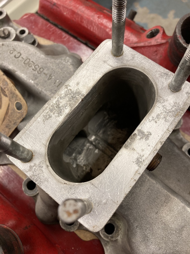 But there was a sting in the tail. Competing with the coupe against the roadsters always had me at a massive disadvantage as I had the biggest, heaviest car and the smallest engine (Great combo). I always felt my biggest time loss was in initial acceleration wether that be start line or exiting corners. My down and dirty idea was to hit it with a small (25-50hp) shot of nitrous oxide on full throttle which would give that much needed boost at the right moment. Nitrous plates aren’t available for Weber 38’s, funny enough. The same friend that did the manifold conversion also made me this one off nitrous plate that also doubled as a 1” carb spacer for linkage clearance. 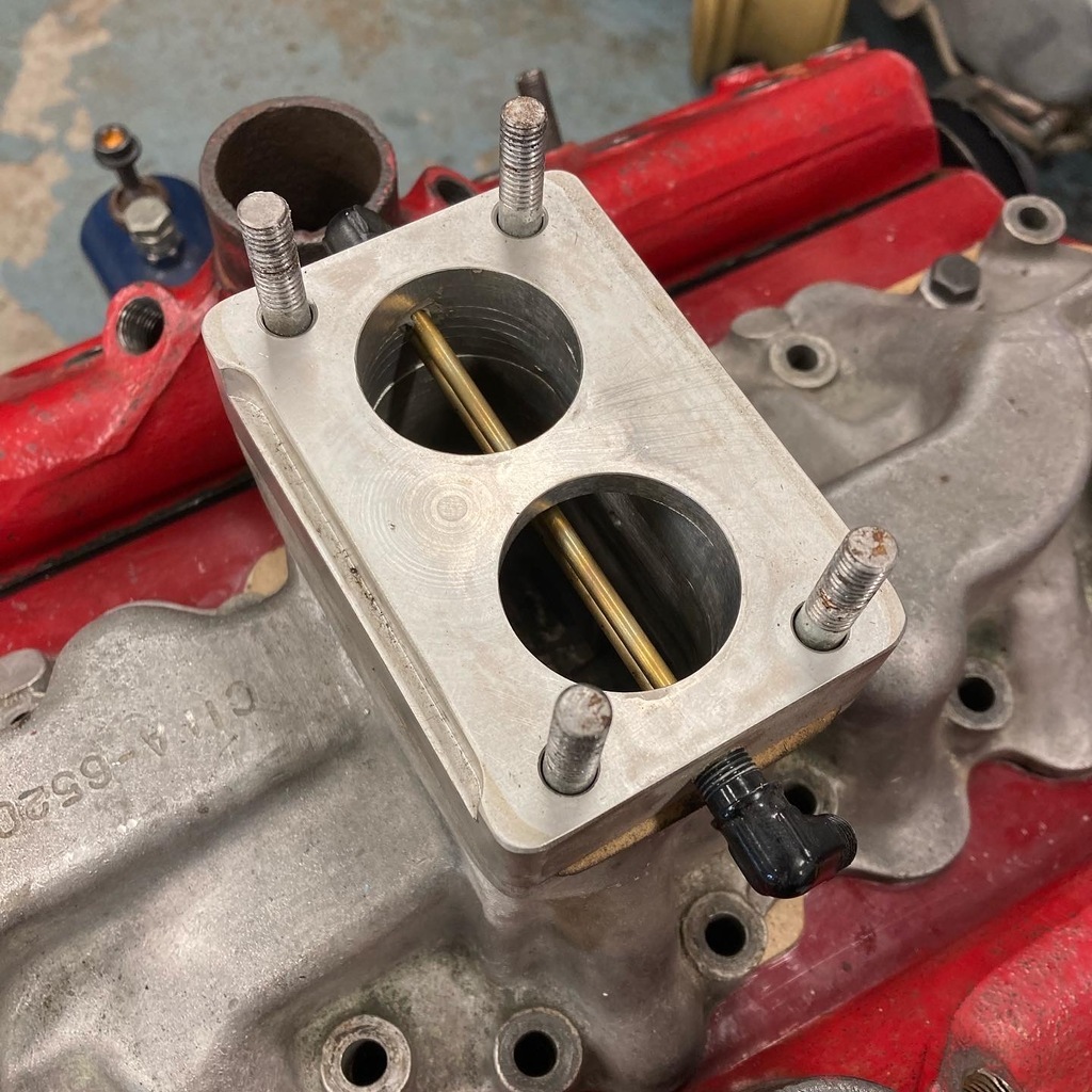 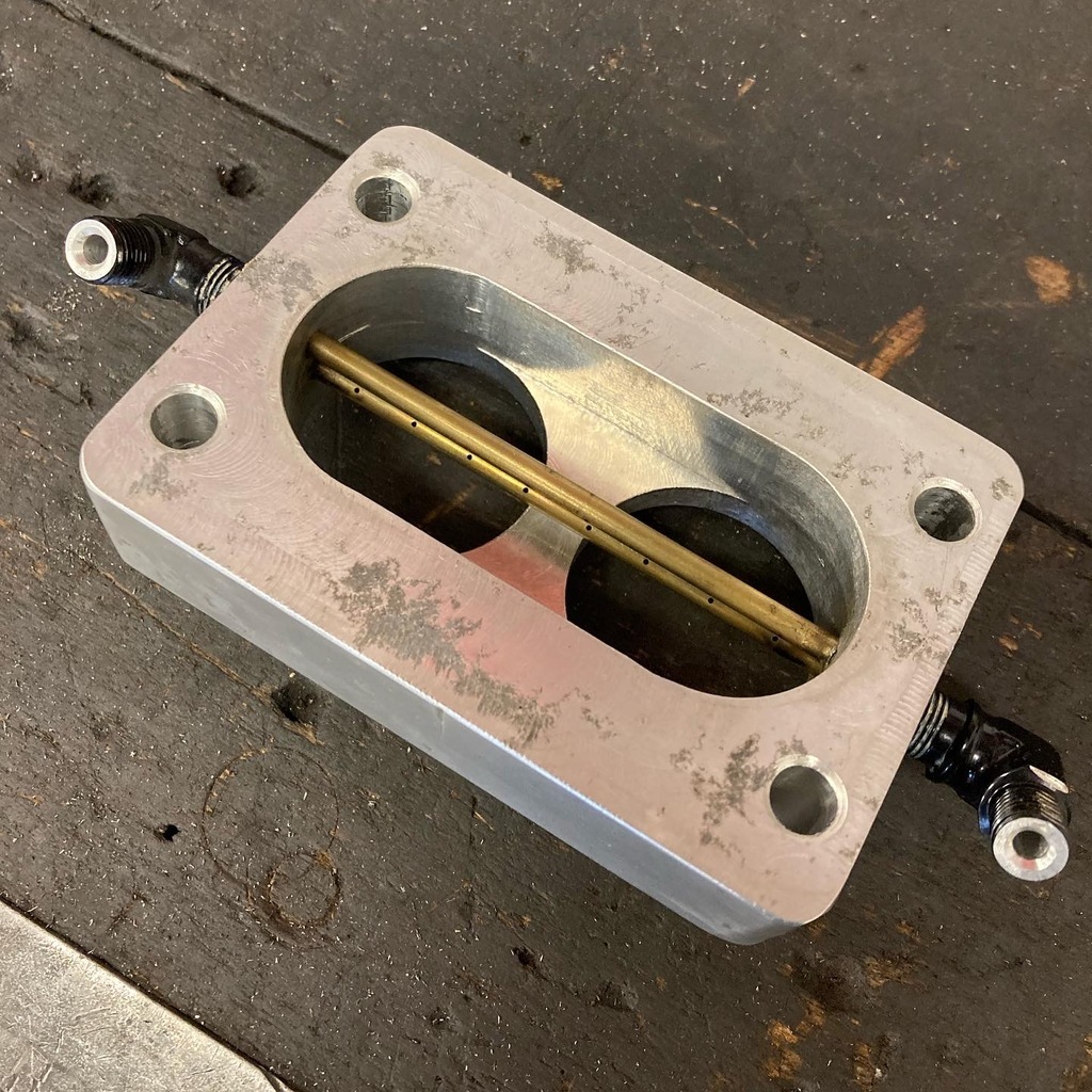 With the hard part done it was plumbed and wired. At this point I had an epiphany. This idea is genius, why has nobody already thought of it? I picked up the Motorsort UK blue book and there it was in black and white, “no oxygent’s”. Bo**ocks. I was so far into it at this point that I decided to continue and had everything ready, I just needed the N2O. I tried and tried and tried. I couldn’t get gas anywhere even vaguely local. The closest place was like a 100+ mile round trip which at this point I said another bo**ocks to it all and binned the whole idea. 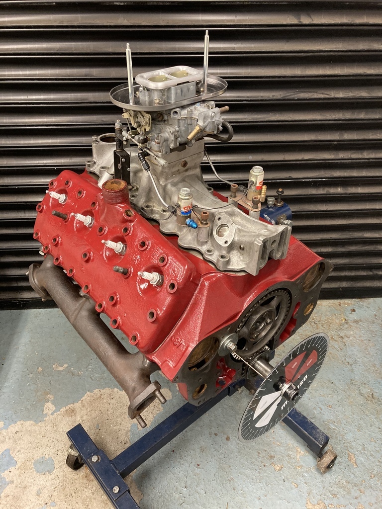 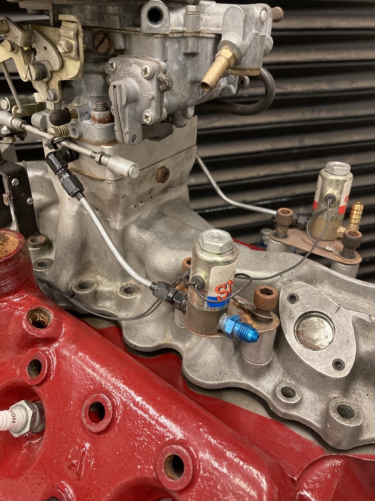 The Weber set-up did live on and worked well. I got it dialled in and headed to the rolling road were it produced the exact same bhp to the dual Strombergs! The Strombergs produced a better torque curve, so overall the dual Strombergs were a better package. Oh, and the Weber did the exact same MPG as the Strombergs as well. I think this is the only picture I have that shows it was ever a thing. 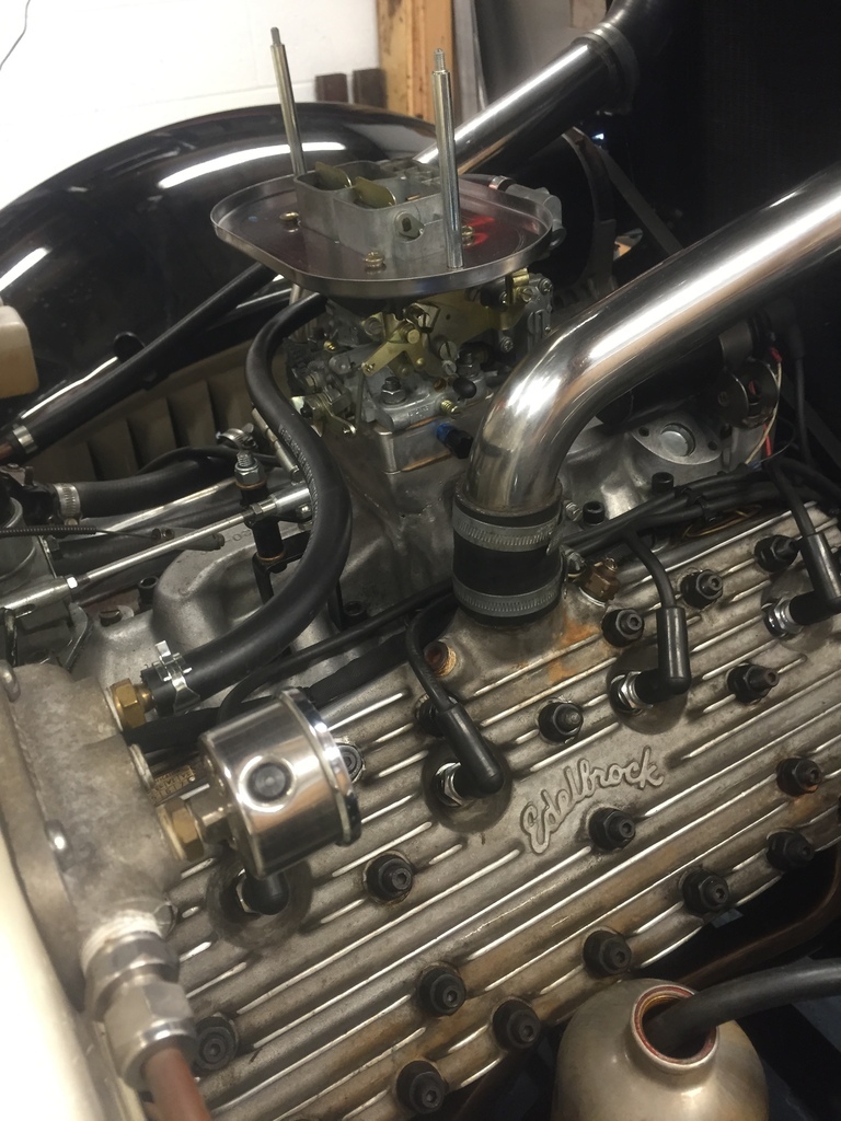 |
| |
|
|
|
|
|
|
|
LOL at Wuhan whirly boi!  |
| |
1968 Mini MkII, 1968 VW T1, 1967 VW T1, 1974 VW T1, 1974 VW T1 1303, 1975 Mini 1000 auto, 1979 Chevette, 1981 Cortina, 1978 Mini 1000 1981 Mini City, 1981 Mini van, 1974 Mini Clubman, 1982 Metro City, 1987 Escort, 1989 Lancia Y10, 1989 Cavalier, 1990 Sierra, 1990 Renault 19, 1993 Nova, 1990 Citroen BX, 1994 Ford Scorpio, 1990 Renault Clio, 2004 Citroen C3, 2006 Citroen C2, 2004 Citroen C4, 2013 Citroen DS5. 2017 DS3 130 Plenty of other scrappers!
|
|
|
|
Enbloc
Part of things
 
Posts: 399
|
|
|
|
With the inlet and turbo decided on next decision was what to do about exhaust manifolds. Running a single turbo I would need to have a crossover from one bank to the other with the combined exhaust then feeding into the turbo. Space and packaging were going to be a major issue. The ‘36 Ford has the smallest engine bay of all the pre-war V8’s as the engine bay tapers into the narrow grille. If I could manage to package it into the ‘36 then it would fit into any of the other Early Ford V8 cars. Add also that I was doing this without the car present and purely working from memory! A full tubular manifold was out of the question due to cost and skill level so the only other option was factory cast iron manifolds. This isn’t so bad. They are very compact, almost indestructible , abundant as most people swap them out and due to the Flatty running for so long and in so many applications there are multiple options for inlet/outlet positions and configurations. My first choice was the last generation of passenger car manifolds from the early 50’s as their layout was perfect. 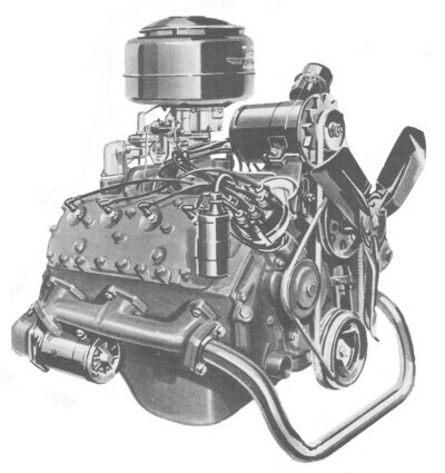 I obtained a nice matched pair and was rather impressed with them. They were a much larger bore than earlier versions and had the internal ports angled for the direction of flow. I then spent a good chunk of time port matching them and cleaning up the castings. I mocked them up, as can be seen above, but the outlet angle wasn’t optimal. The real kicker was the crossover inlet/outlets. The early 50’s cars had a different water pump/engine mount layout which meant that when I bolted the earlier style water pumps on they completely clashed. Attempt two consisted of digging out the stock of manifolds but nothing really worked. 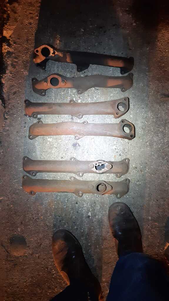 Attempt three I just started looking at images of exhaust manifolds in the hope that something may be workable. I found a listing on EBay that had the same style paired manifolds but with the crossover in a much more usable place for me. 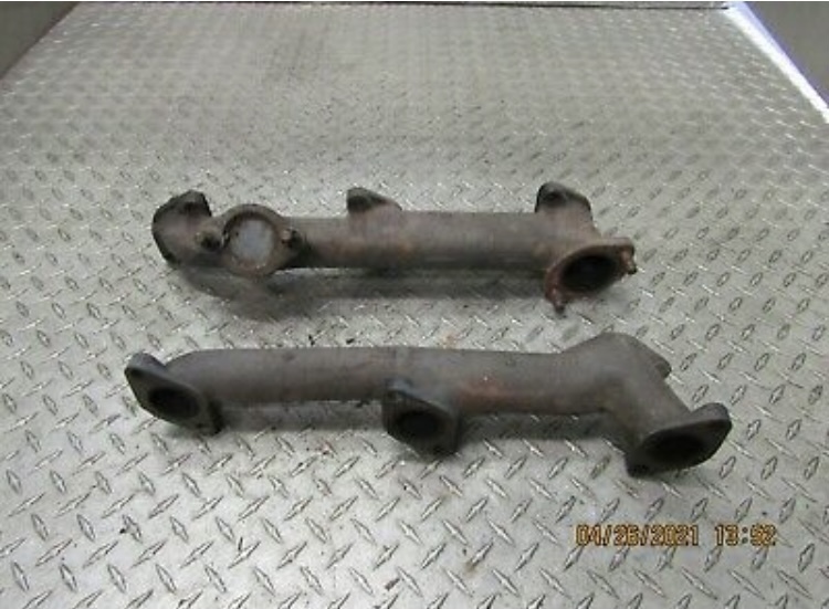 They are I believe early 50’s pickup and though not as free flowing as the passenger car versions worked out rather well for what I wanted. |
| |
|
|
|
|
|
|
|
|
|
|
|
| |
1968 Mini MkII, 1968 VW T1, 1967 VW T1, 1974 VW T1, 1974 VW T1 1303, 1975 Mini 1000 auto, 1979 Chevette, 1981 Cortina, 1978 Mini 1000 1981 Mini City, 1981 Mini van, 1974 Mini Clubman, 1982 Metro City, 1987 Escort, 1989 Lancia Y10, 1989 Cavalier, 1990 Sierra, 1990 Renault 19, 1993 Nova, 1990 Citroen BX, 1994 Ford Scorpio, 1990 Renault Clio, 2004 Citroen C3, 2006 Citroen C2, 2004 Citroen C4, 2013 Citroen DS5. 2017 DS3 130 Plenty of other scrappers!
|
|
Enbloc
Part of things
 
Posts: 399
|
|
|
|
With the manifolds decided on and turbo in hand it was time to mount the turbo and create the hot side plumbing. In the picture above of the inlet manifold you’ll notice the front portion of the inlet is a large cast upstand. This is also drilled and tapped for a 9/16” stud. It’s job is the mount for the original dynamo. 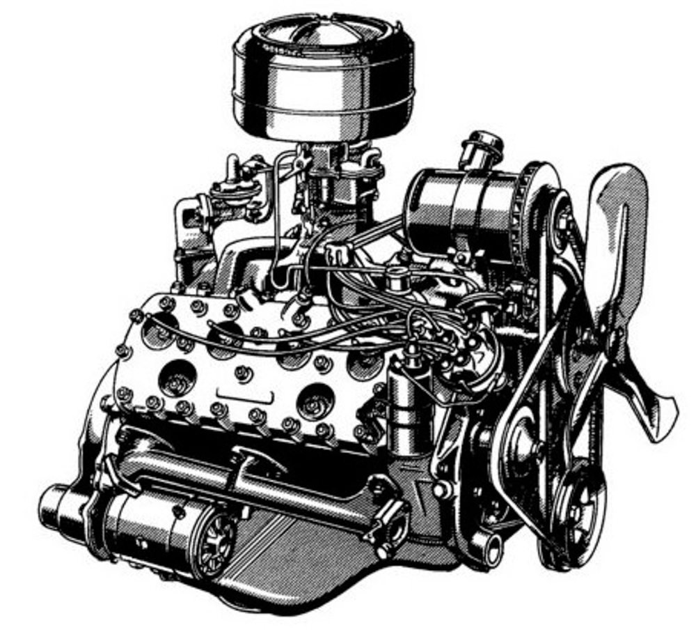 It’s common to remount the dynamo to either head when running multiple carb manifolds as the second, third or fourth carburettor will take up the space where the dynamo once lived. 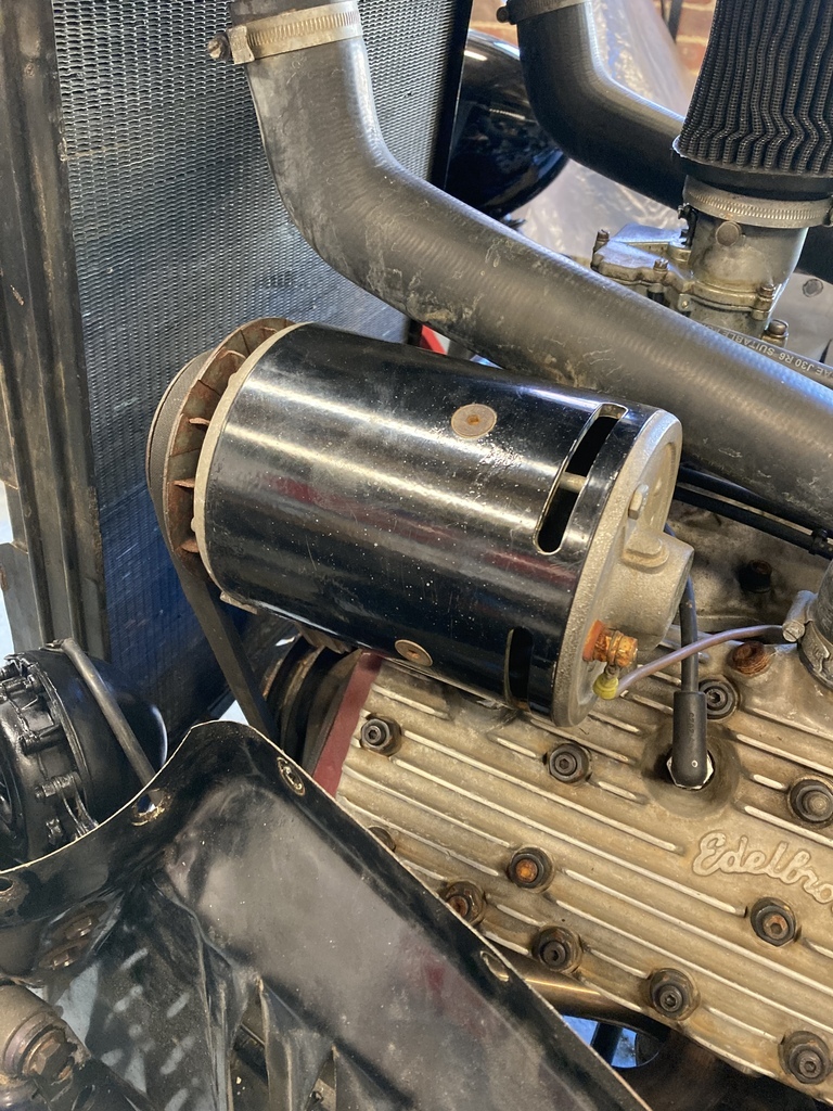 A stock dynamo is kinda the size of turbo and they are about the same weight as well and I just happen to have this dynamo mount sitting unused. Mmm… I got myself a 12mm laser cut T3 style exhaust flange and some 10mm and 3mm plate. I put together a simple upstand that sat in the groove of the dynamo mount making sure I optimised the angle of the turbo for clearance of the Weber, lateral location for clearance of the rad hoses and trying to pull it all in as tight as possible to the engine. 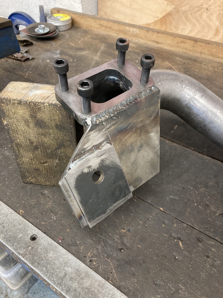 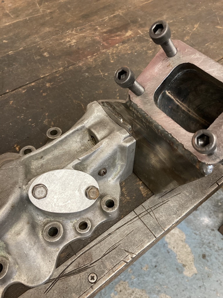 Turbo mounted it was just a case of connecting it all up. The original outlet of the exhaust was a odd size like 2 1/8”. I could open up the outlet to 2 1/4” but couldn’t go any further because of the spacing of the stock exhaust studs and having to leave enough clearance to actually get a fixing in. I used a short section of flared exhaust pipe to step up again from the flange to a much more usable 2 1/2” exhaust pipe size. With a little grinding and a little clearance it all ended up very tight but usable. From there I used pre-made mandrel bends from Jetex to snake my way up to the turbo. 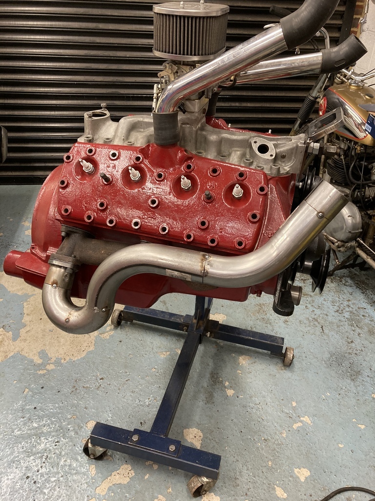 Still very aware of space and working from memory again it was a case of tucking it all in as close as possible to the engine. Finally an external wastegate was needed. This was an area I didn’t want to skimp as accurate and reliable control over the boost generated is one of the most important aspects for a making a safe system. I went with a 44mm wastegate from Australian company GFB, which as you’ll see becomes a bit of a theme. It came with a V-band style clamp that needed a 1 3/4” upstand. You can pretty much mount these anyway but good practice is to have them angled in the direction of flow for best efficiency, which I did. The wastegate exhaust pipe has been left at this point as style (Hater pipe out the top?!) will need to be finalised when fitted in the car. 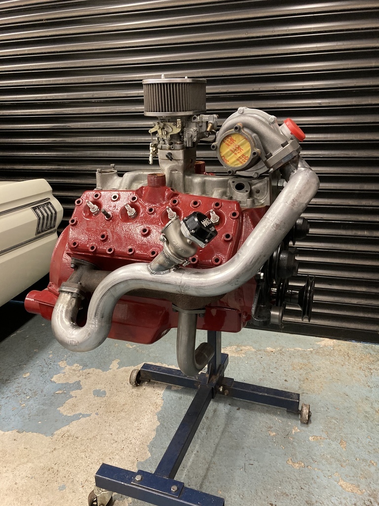 Everything was still just tacked at this point and with it all finalised it was fully welded creating this. 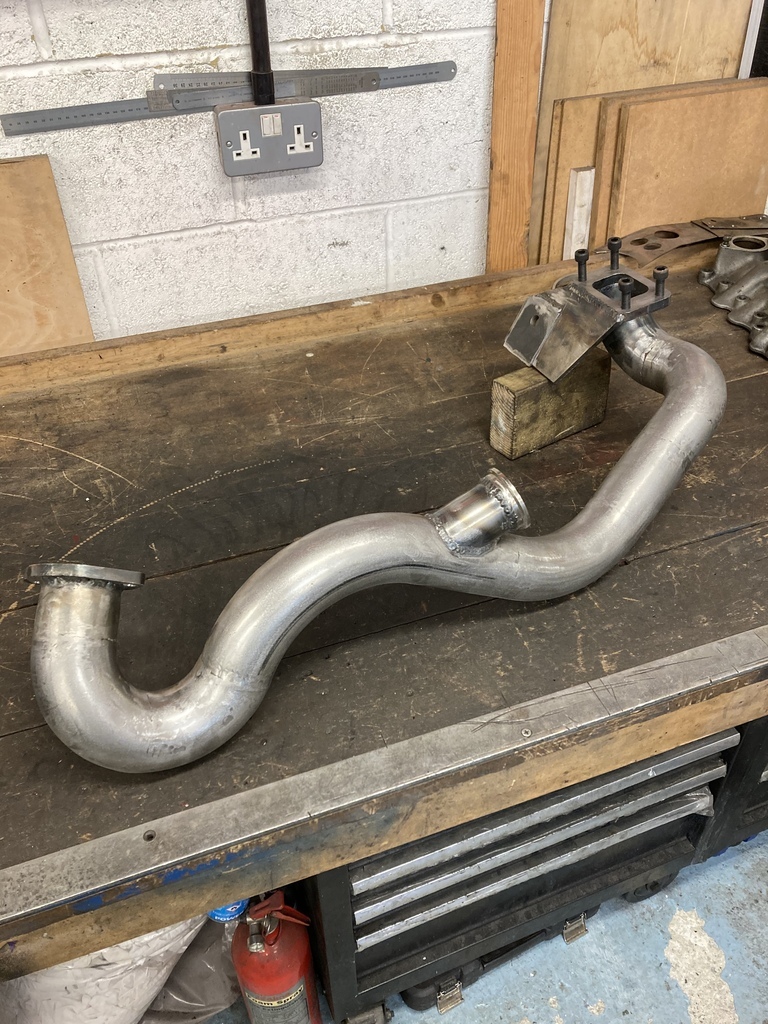 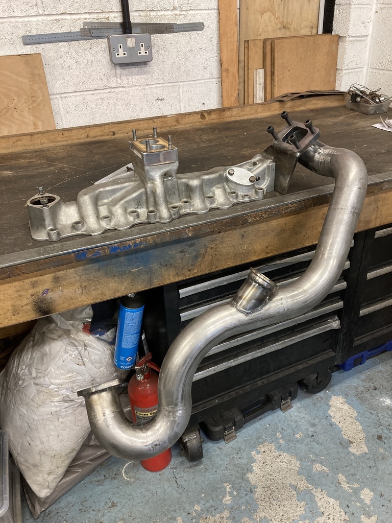 |
| |
|
|
|
|
|
|
|
|
|
|
You had me at flange.
Cracking reading.
|
| |
|
|
Enbloc
Part of things
 
Posts: 399
|
|
|
|
I had been researching using Weber 38’s in blow thru applications and it was all looking very grim. Endless opinions on why it doesn’t work but I thought I knew better until someone, somewhere on a long dead forum thread explained it perfect. “A carburettor has a fixed jet. It can be tuned for no boost or it can tuned for maximum boost but you can’t have both” This leads to the situation where you set-up fuelling for off boost and it leans out under boost or you set-up fuelling for maximum boost and it runs rich everywhere else. Then throw in the infinite variables of on/off load, variable throttle positions and boost output not related to engine demand and it all gets very messy for a carb. So, fuel injection it is. Ignition was also something I hadn’t really thought about up to this point. Basically there was only direction to go. Fuel injection and fully mappable ignition. It’s all getting a little serious now! I had built myself into a corner at this point as the system had been built around the modified inlet for the Weber. I remembered that Webcon did a replacement fuel injection unit for the Weber. 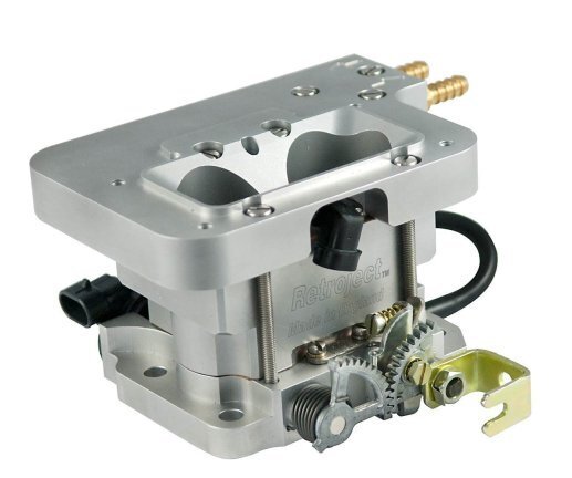 The Retroject unit was perfect for my application. Dimensionally identical to the Weber and uses the same throttle arms so I could use all my previously made throttle linkage. The Retroject includes fuel injectors, fuel pressure regulator, air temp sensor, throttle position sensor and idle air control valve all built in. This greatly simplified installation for me. 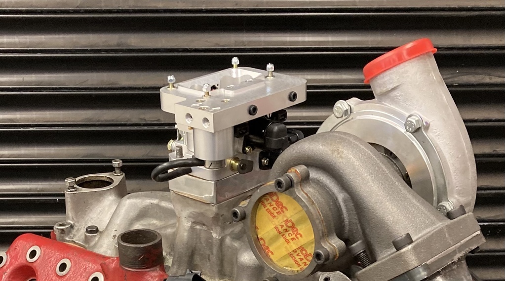 How to control all this? An ECU. So many to choose from now and they’re all pretty good. I wasn’t that excited with the DIY end of the market (mega squirt/megajolt) or becoming a laptop w****r! I found myself drawn to Haltech. I like them as a company and I like the way they have simplified everything and made it very user friendly. The UK dealer was very helpful and had what I wanted in stock. 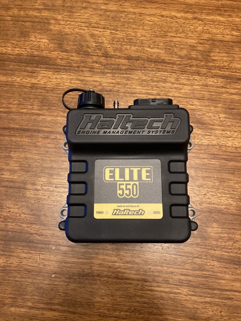 This will be fun. 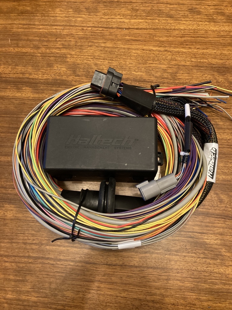 |
| |
|
|
jamesd1972
Club Retro Rides Member
Posts: 2,921  Club RR Member Number: 40
|
|
|
|
|
An efi turbo flathead ! Can’t be too many of those in the UK, so wrong but right.
Love this, keep the updates coming.
James
|
| |
|
|
Enbloc
Part of things
 
Posts: 399
|
|
May 20, 2022 15:57:14 GMT
|
Fuel injection decided on and a fully capable ECU the no brainer for the ignition side was to go full mappable which would mean dumping the dizzy completely and going to a trigger wheel set-up. I had a dual crank pulley from a early 40’s Ford. The rear pulley drives the water pumps and alternator and the front pulley drives the mechanical cooling fan in its original application. I don’t run mechanical fans so the front pulley is redundant. 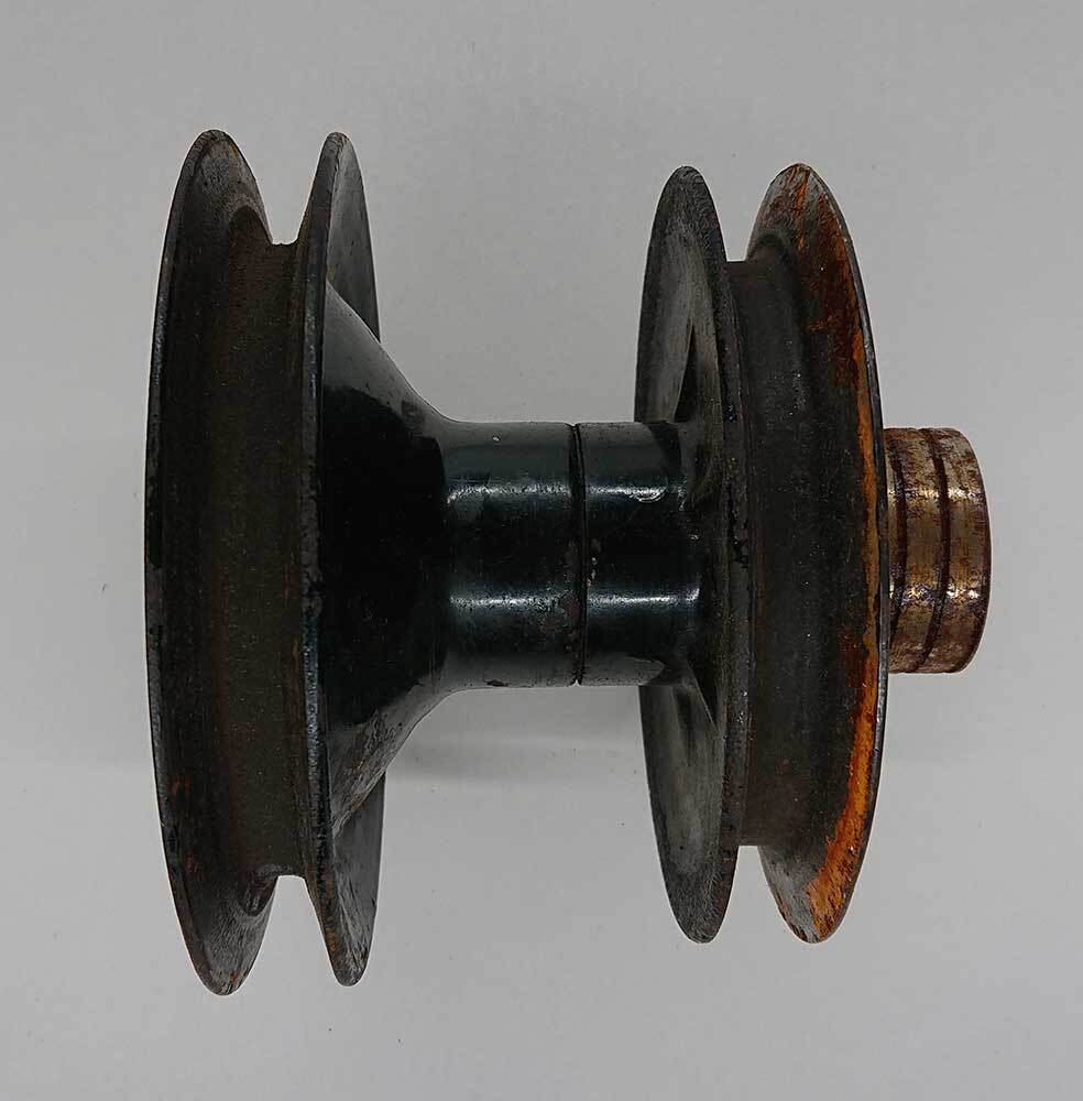 The first thing I needed to do was mount a 36-1 trigger wheel to the pulley. 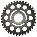 What is a 36-1 trigger wheel? Its a wheel of 36 teeth with 1 tooth missing. 360/36 =10. Each tooth equals 10 degrees of crank rotation. A magnetic pickup is triggered with the passing of each tooth with the missing tooth being the base line position for the ECU to know where the crank is in its rotation. Simple, huh? I purchased a laser cut trigger wheel for adapting to the pulley but the stock pulley doesn’t lend itself well because of its stamped steel construction. On closer inspection I found that the pulley had a machined steel centre with the stamped pulleys spot welded to the centre. I carefully removed the welds with a spot weld drill bit but still couldn’t get the pulley off without wrecking it. I had an idea and put the pulley in the press and with a small amount of pressure and loud bang the two separated with barely a scratch. 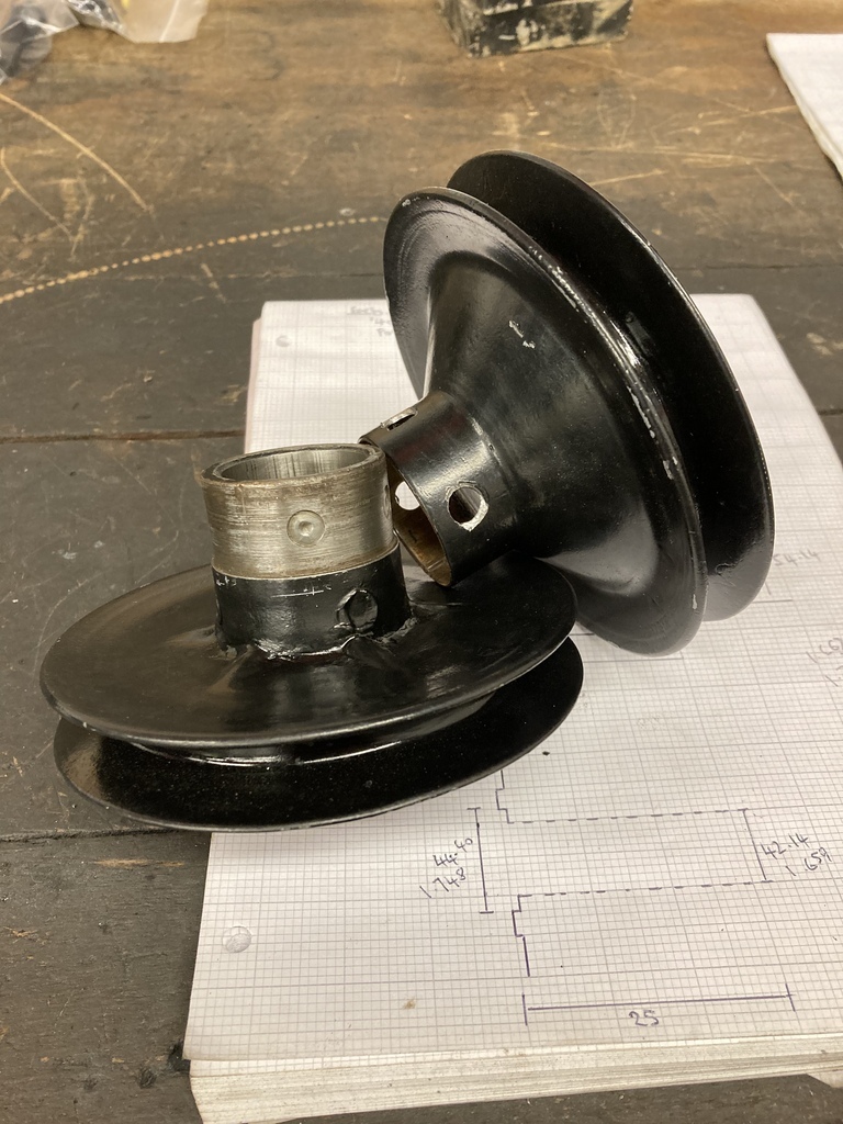 I now had something I could mount a hub to for the trigger wheel. I started turning up an aluminium hub that sat the trigger wheel in as close to the engine as possible. 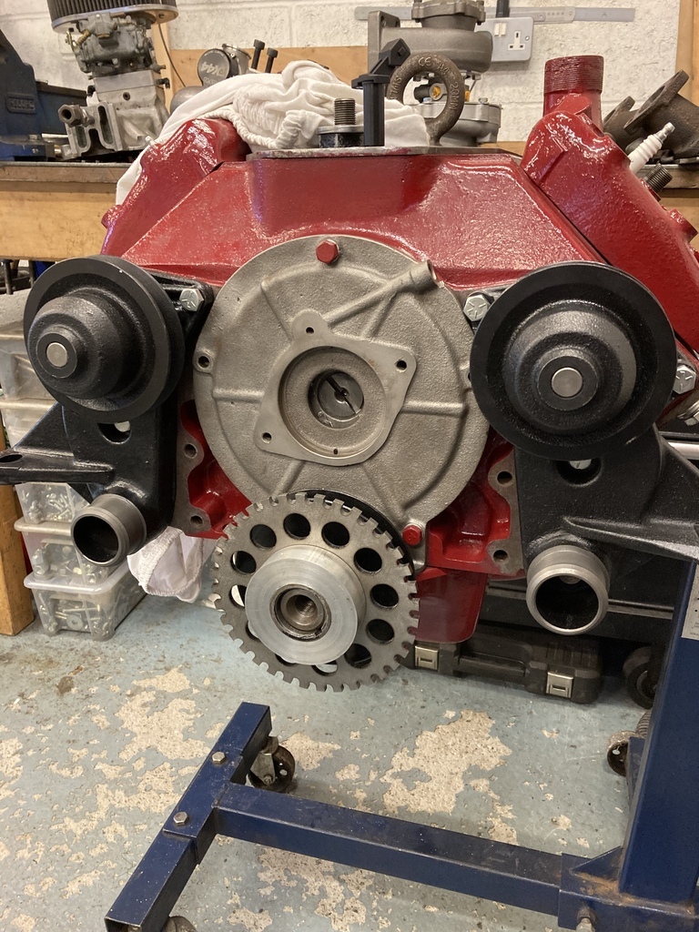 The toothed wheel I chose had pre-cut slots for adjustability. This isn’t really necessary as once the wheel position is set it doesn’t move and any decrepences in position can be trimmed out via the ECU. The reason I went for this particular one was the overall diameter was right and, well, speed holes! I now had to mount the wheel to my hub with 3 perfectly spaced holes. First job was to mount my degree wheel to the lathe. I used some scrap nylon to create a holder and mounted it to the back of the spindle with a bent wire pointer. I also mounted a scribe in the tool post and centred it the spindle. The idea of mounting the degree wheel is so I can now accurately mark off 3 holes exactly 120 degrees apart. The hub was chucked back in the lathe and the scribe positioned to mark the hub on the centre line of the slots. With a centre line marked on the hub I then had to scribe across at 0, 120*, 240* and back to 0 to check for accuracy for my own sanity! This was the outcome ready to be centre popped, drilled and tapped for 1/4” UNC hardware. The slots were actually 8mm but I didn’t want the weight or size of 3 M8 bolts so I also made 3 bushes to take up the gap between the 1/4” bolt and the 8mm slot and to also act as a washer under the head of the bolts. 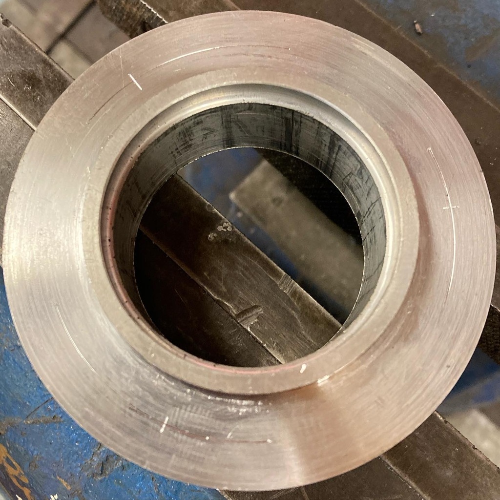 And done. Next was to mount the trigger wheel hub to the pulley. I again repeated the above lathe method to mark 3 hole positions on the outer edge of the hub this time. You’ll notice a theme of 3’s and conscious effort to reduce mass/weight. This is because the whole engine rotating assembly had been balanced and I was now adding all this extra junk on the front that had never been accounted for. To minimise it’s effects as much as possible I went with groups of 3’s so they hopefully balance each other out and to use as small fixings as possible to add the least amount of extra weight. Each hole was carefully set-up in the drill press and drilled and tapped through to the centre for 1/4” UNC set screws. 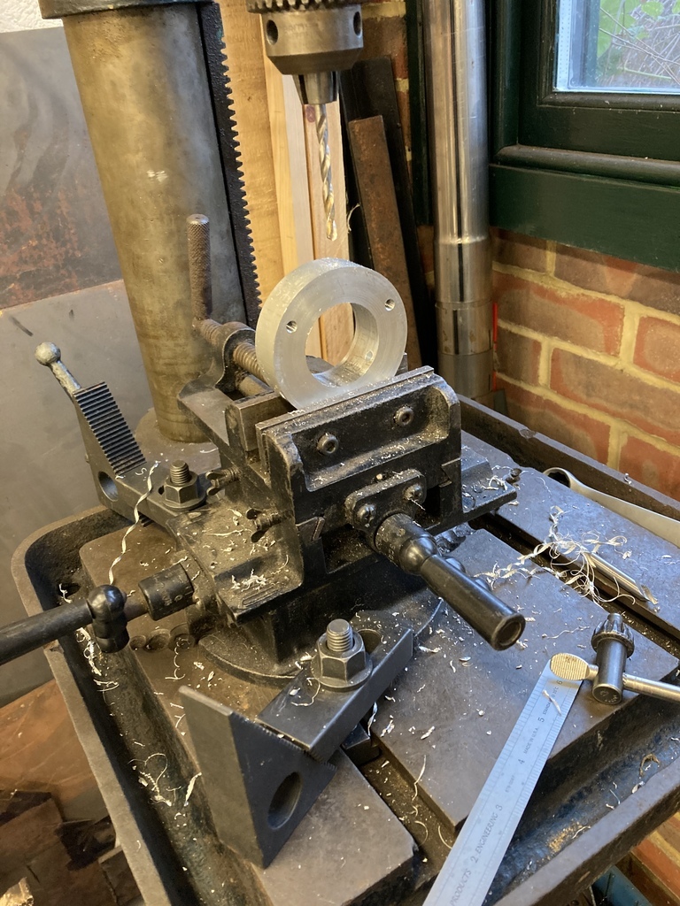 A simple blanking plate with a right angle bracket was made to hold the magnetic pickup and placed where the original dizzy would go. To finish the missing tooth had to removed. The “standard” is 50* BTDC. With the engine at TDC is was a matter of counting 5 teeth round cockwise from the pickup and removing that tooth. 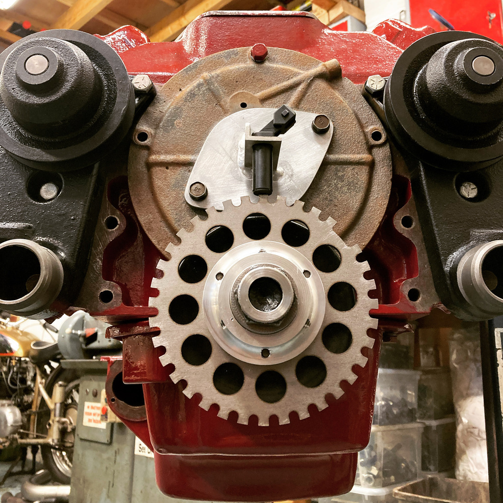 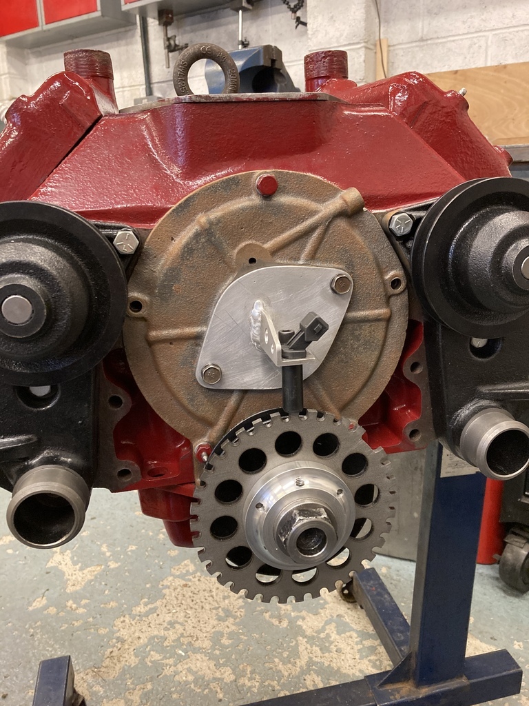 |
| |
Last Edit: May 20, 2022 16:00:36 GMT by Enbloc
|
|
Enbloc
Part of things
 
Posts: 399
|
|
May 27, 2022 15:26:29 GMT
|
With the control side of the ignition done it was time to think about how to actually fire the plugs. I looked at EDIS which is pretty cheap and fool proof but it’s advancing in years now. 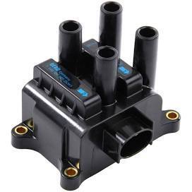 It was suggested that pretty much any modern coil pack would work, which is true. But with the project steaming ahead I had a real hankering to go coil on plug. Go big or go home, right? I have this kink where I like to attach as much engine paraphernalia to the engine itself rather than randomly bolting stuff around the engine bay. I always liked the way LS coils bolted to the top of the rocker cover and a Flatty just happens to have these large, wide, flat heads. 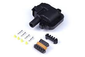 Flathead heads are interchangeable bank to bank and are a mirror image across their face which would greatly simplify the CAD template. I would only need to mark out a template for 2 coils which I could then flip and turn for the other 6 coils. I decided on coil positions that managed to avoid the head studs and spark plugs and again with thoughts of space I sank the coils into the brackets to pull them in as close as possible to the engine. This is what I came up with. 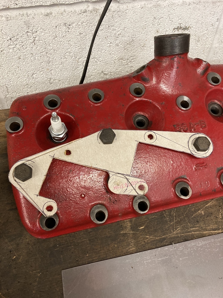 I had some 2mm steel guillotined into strips as a starting point and transferred and drilled all the necessary holes over. 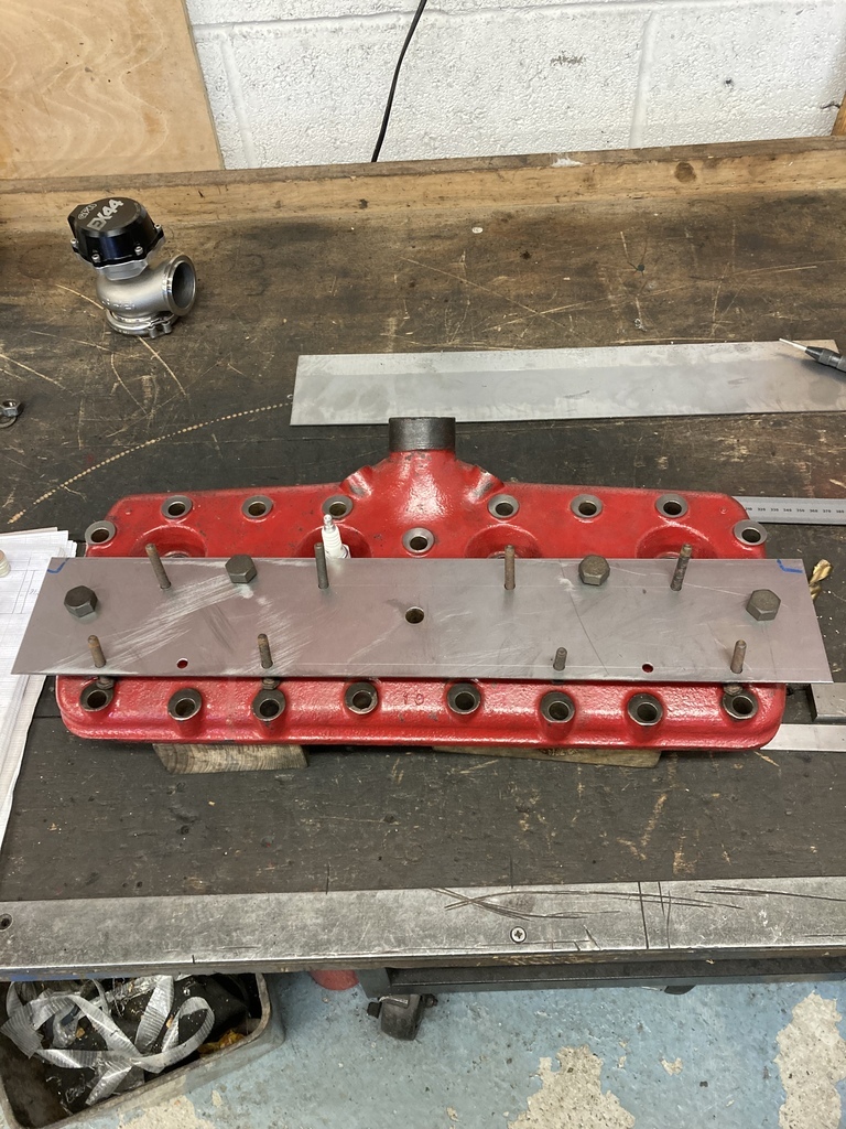 With the brackets all cut out and assembled I could try it on the engine. Win. 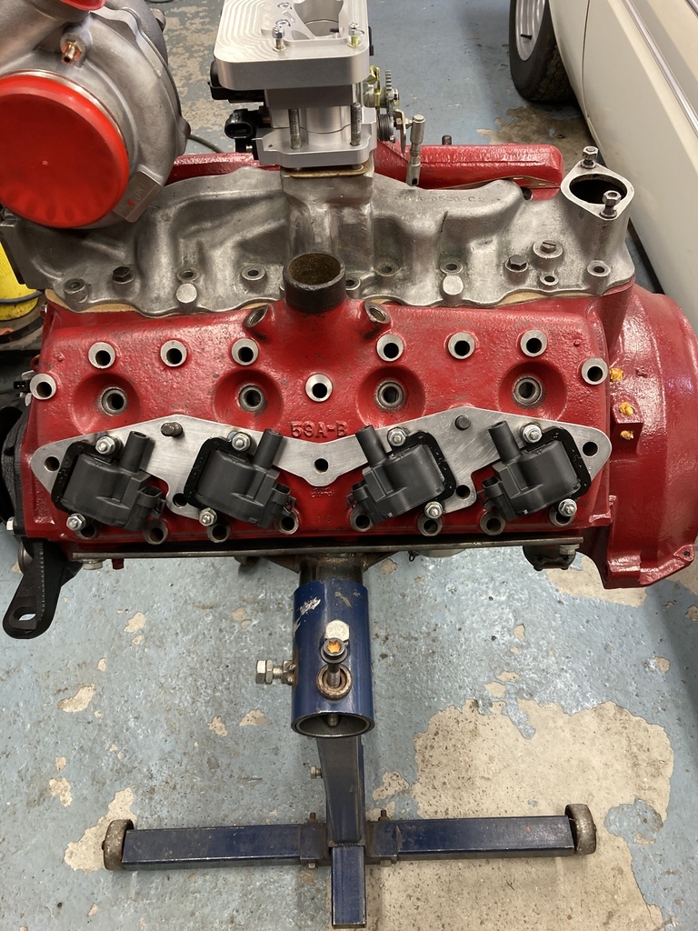 I then tried the assembly on the busy hot side of the engine. Fail. 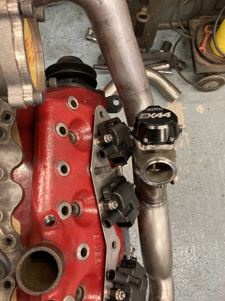 The front coil was touching the wastegate and second one wasn’t great for clearance either. Luckily I still had space to play with. I created an add-on template to the first which would swing the front coil up out the way. The second coil, not so much. I’m just going to live with the clearance on that one and see if it survives. 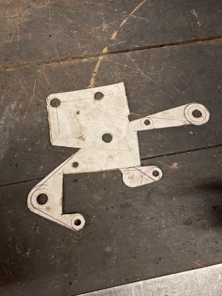 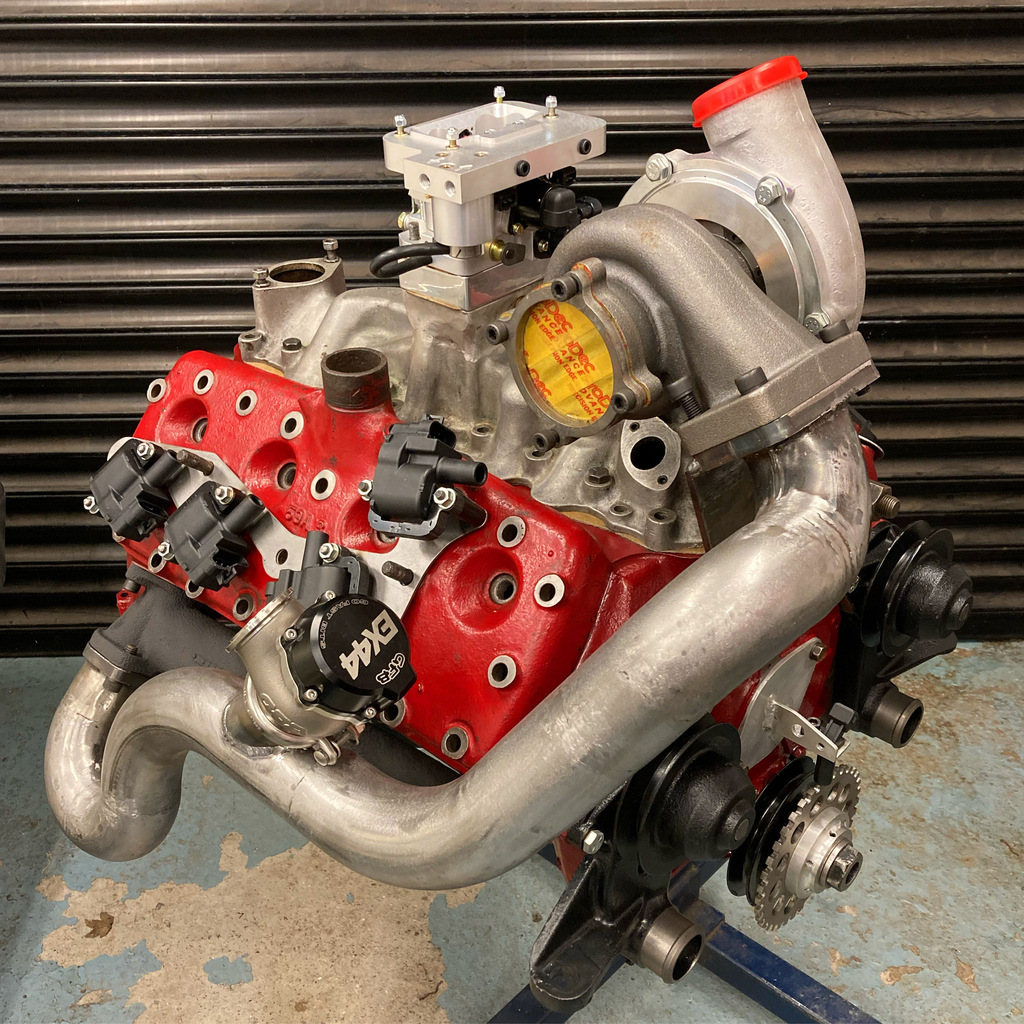 The two finished brackets got long 1/4” UNF bolts welded in to act as captive studs for the coils and I turned up a load of nylon spacers so the the coils are completely floating in the brackets and isolated from heat as much as possible. 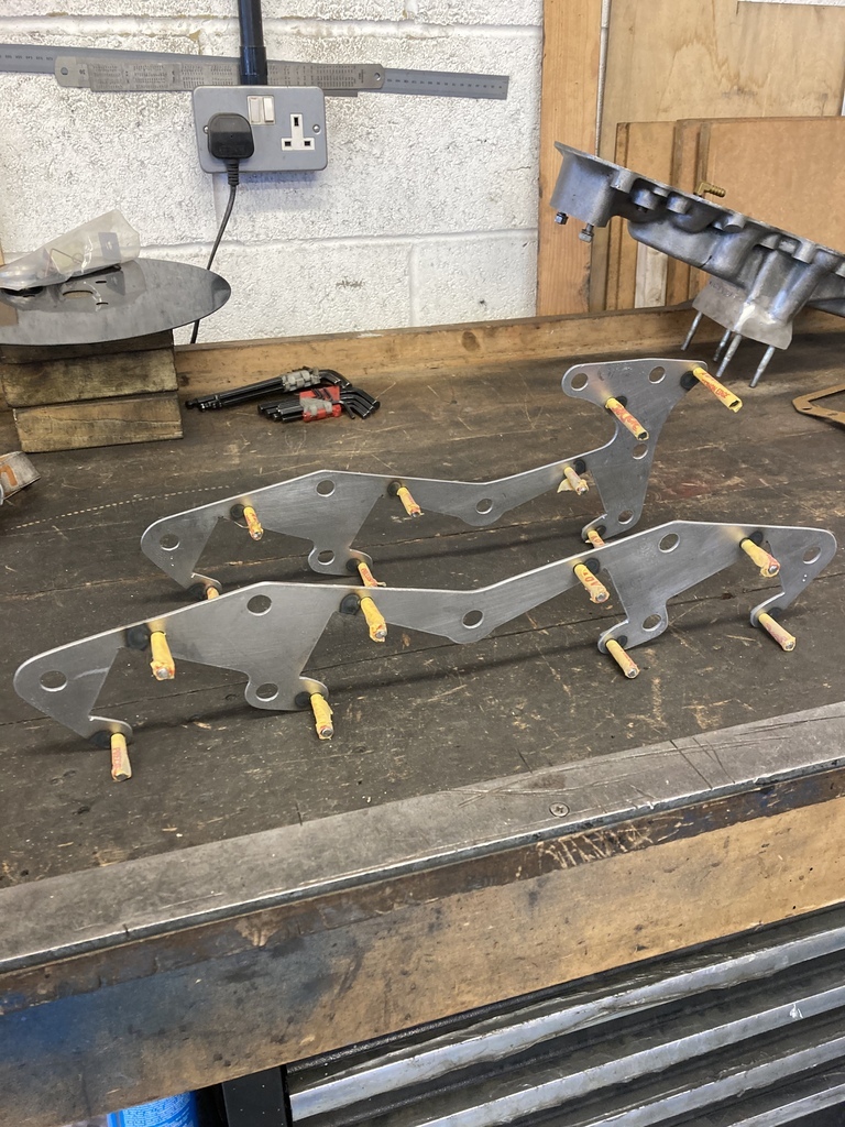 This just left ignition wires to finish. The plugs ends are conventional but the LS coils have a specific terminal and boot which I had to order. The ignition wires themselves are so ridiculous short that I managed to use up all the useless short off-cuts you evidently end up with. 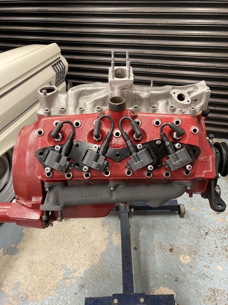 |
| |
Last Edit: May 27, 2022 15:40:12 GMT by Enbloc
|
|
|
|


