gazzam
Part of things
 
Posts: 746  Member is Online
|
|
Oct 15, 2022 11:14:10 GMT
|
Finally back to the Triumph. But first, with your indulgence, my excuse. Have been busy with other stuff - the Ducati is well under way. Couple of photos, hijacking my own thread. 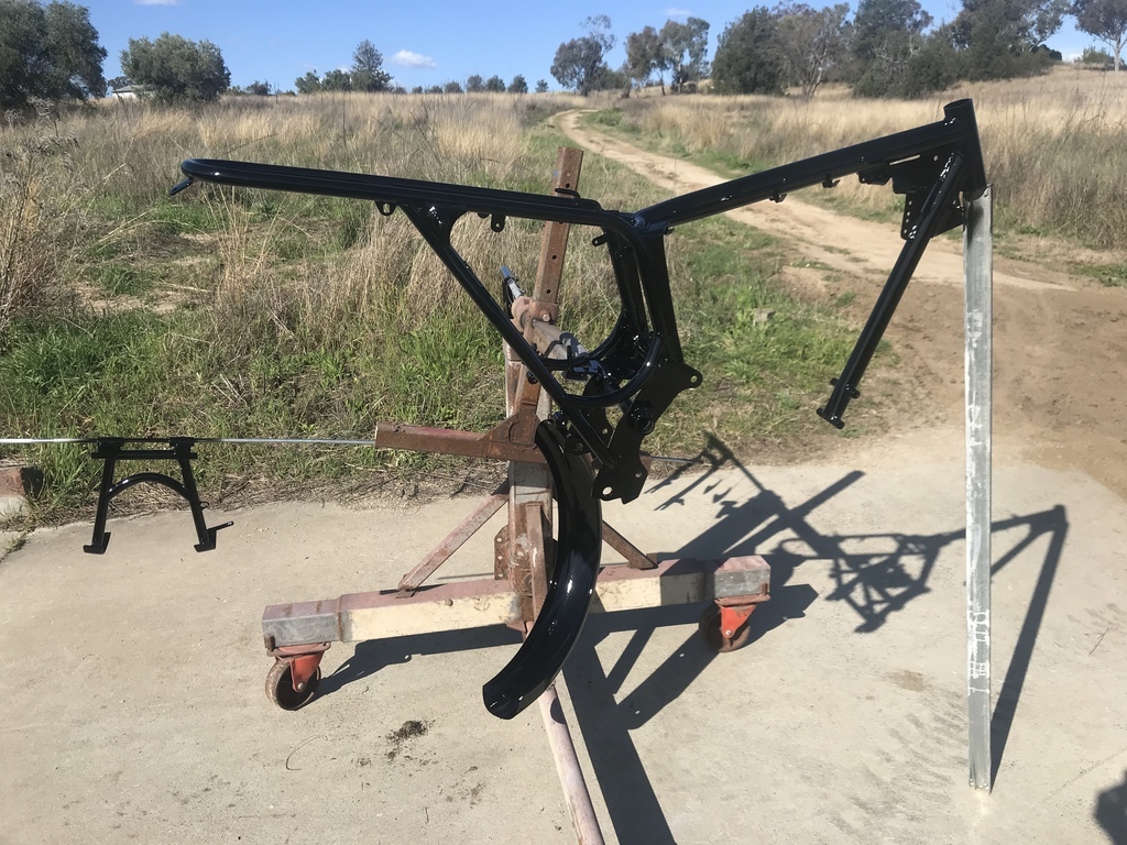 That’s the frame after stripping and painting. It had lots of chips, marks etc. It would have bugged me forever if I’d left it as it was. The only way it will look like a proper job is to do a proper job. Engine in after much alloy polishing and plating of many nut and bolts. 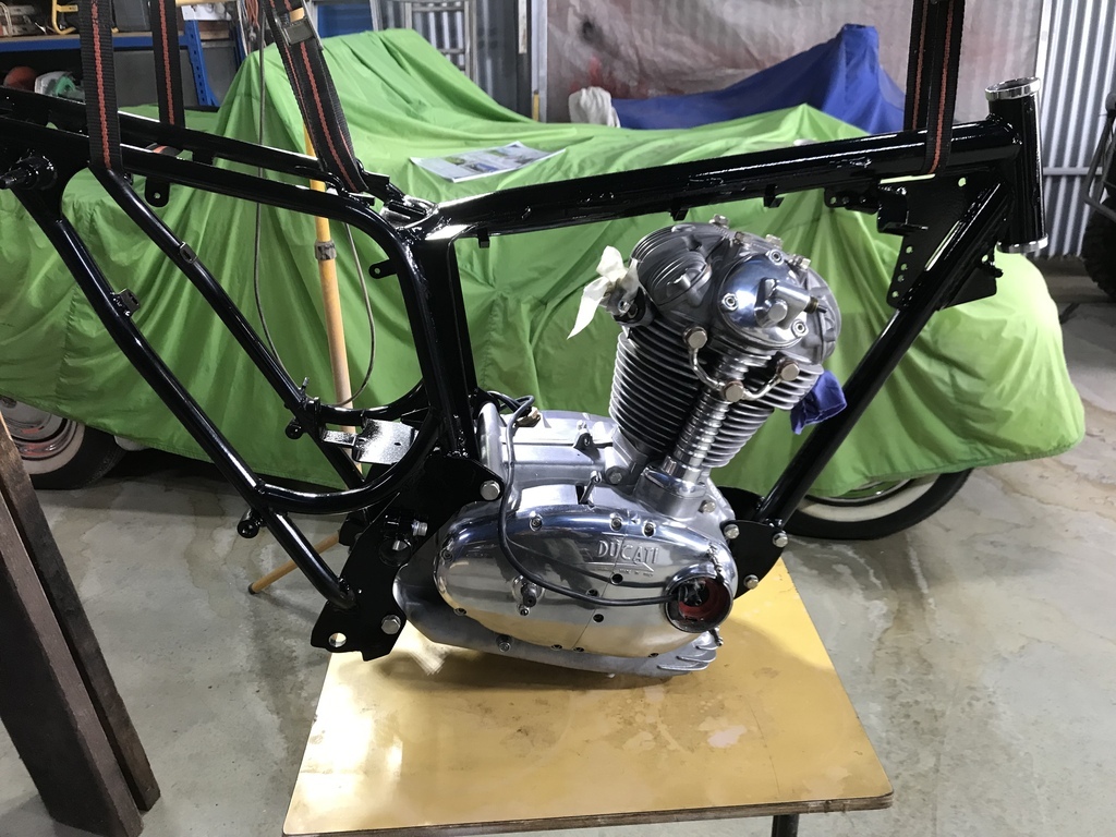 Lots more pieces back in place. 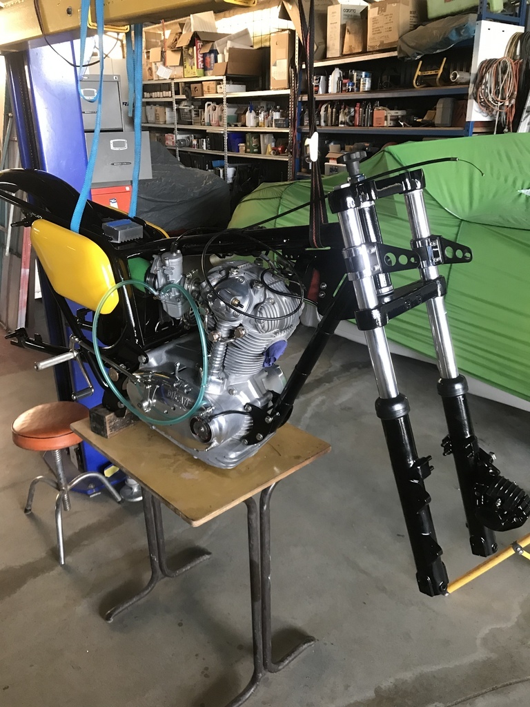 Swingarm back in the frame, waiting on the shock nuts to come back from chromers. 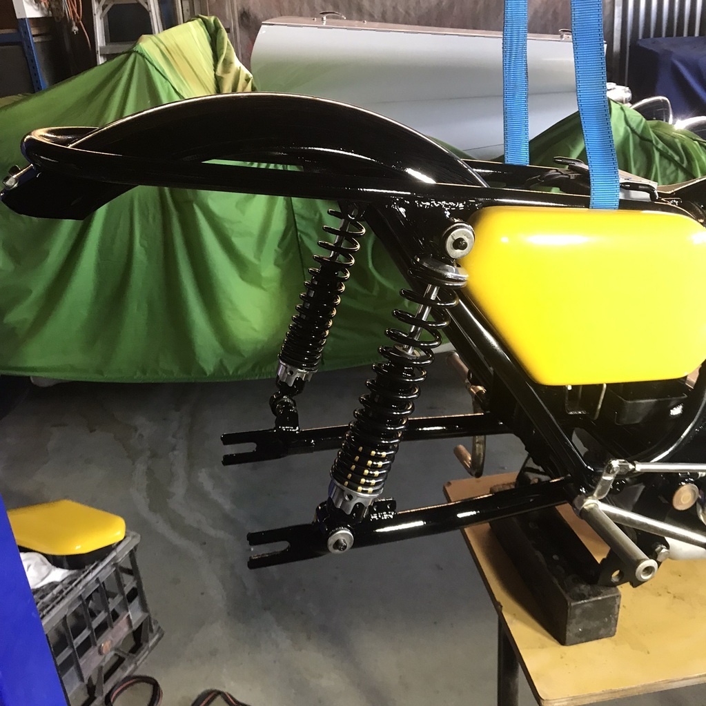 Back wheel in. 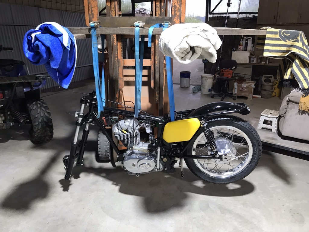 Also been fiddling with a big old bandsaw I’ve had for years. It is/was a meat saw and was way too fast to cut steel. Just burnt the teeth of the blade. So I had to gear it down ( a lot ) to make it work on steel. That involved a lot of work with aluminium. Made one large pulley ( about 320mm ) by cutting a circle and a strip from 5mm plate. 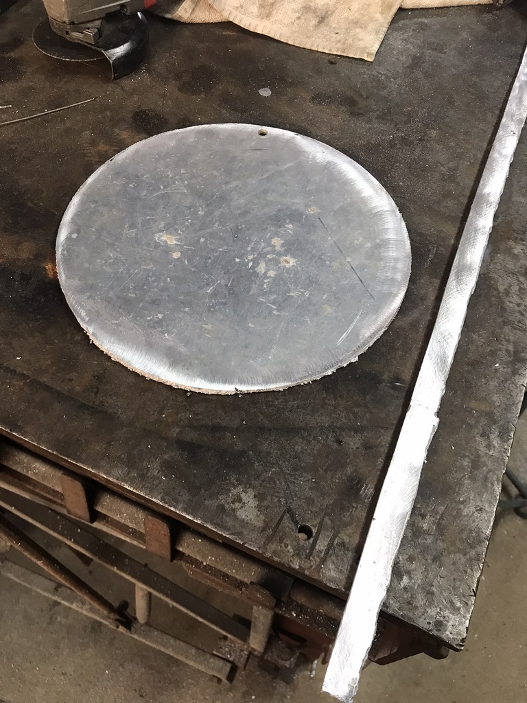 Roll the strip to the diameter of the circle. 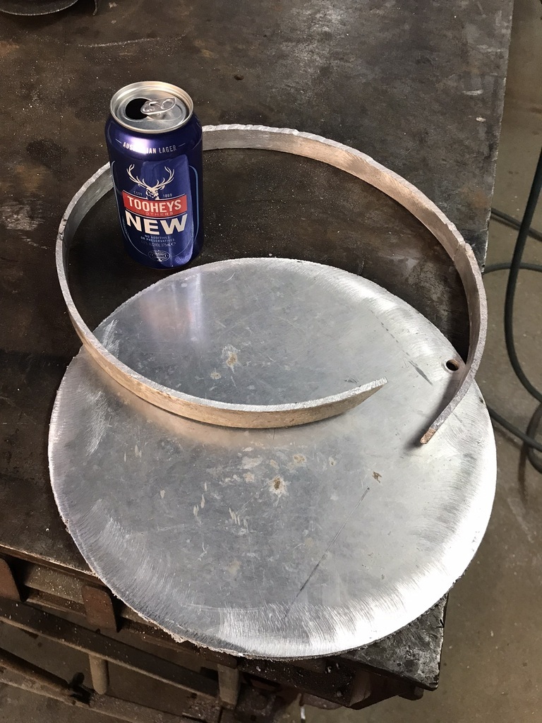 Cast several blanks to make hub and other, smaller pulleys. 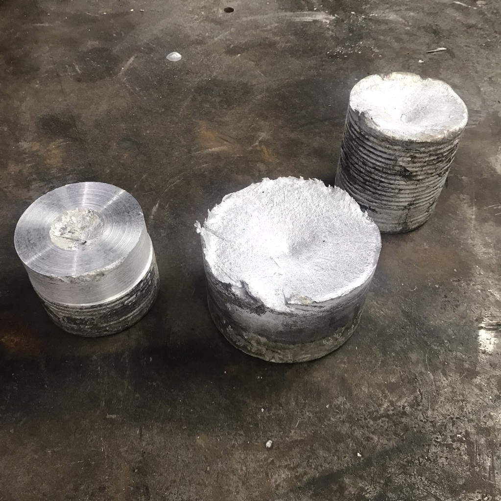 Weld a hub to the plate circle and true it up in the lathe. 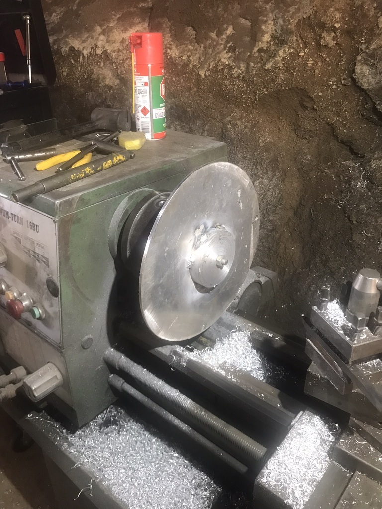 Weld rolled strip to outside and turn to form a vee groove. Weld is extremely ugly mainly because of lack of ability. Also right at the limit of welder capacity. Also in the photo is one of the small pulleys made from the previous castings. 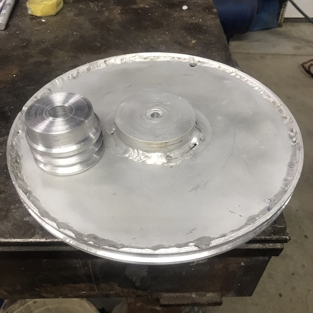 Used an old bike wheel as a pulley. 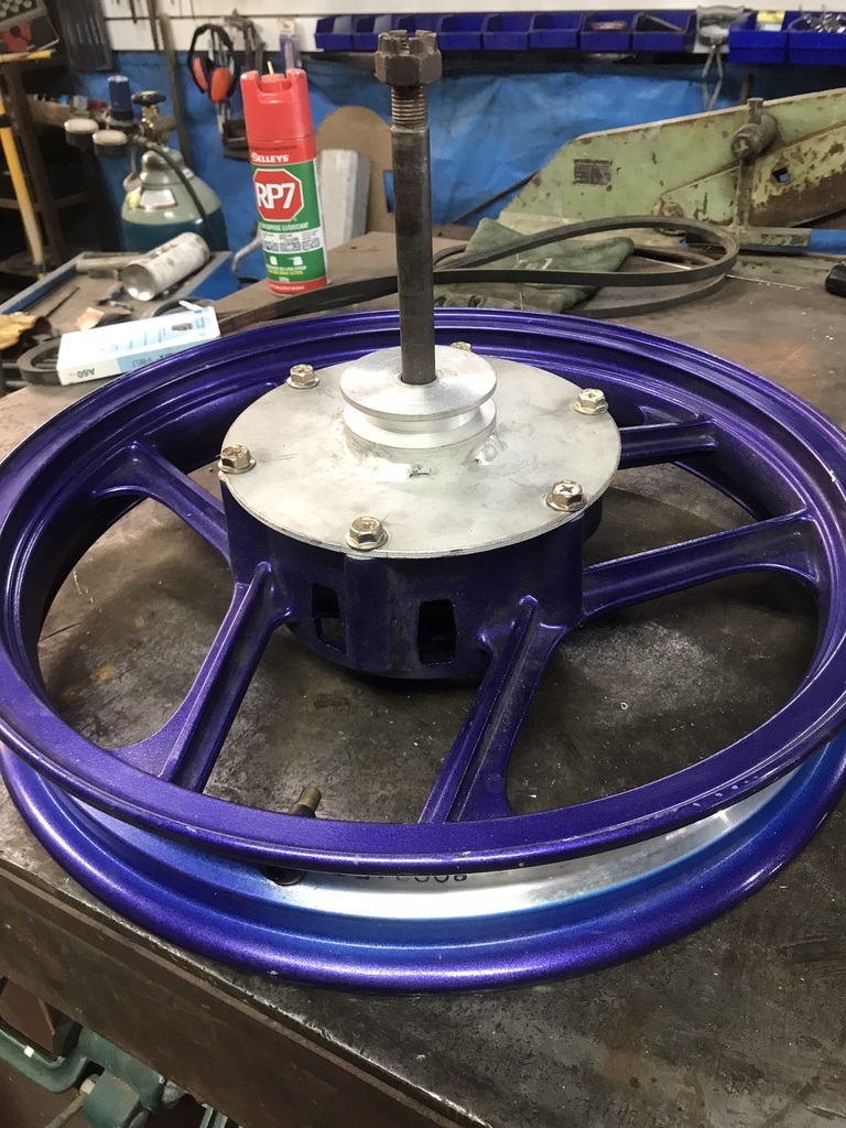 The whole contraption. 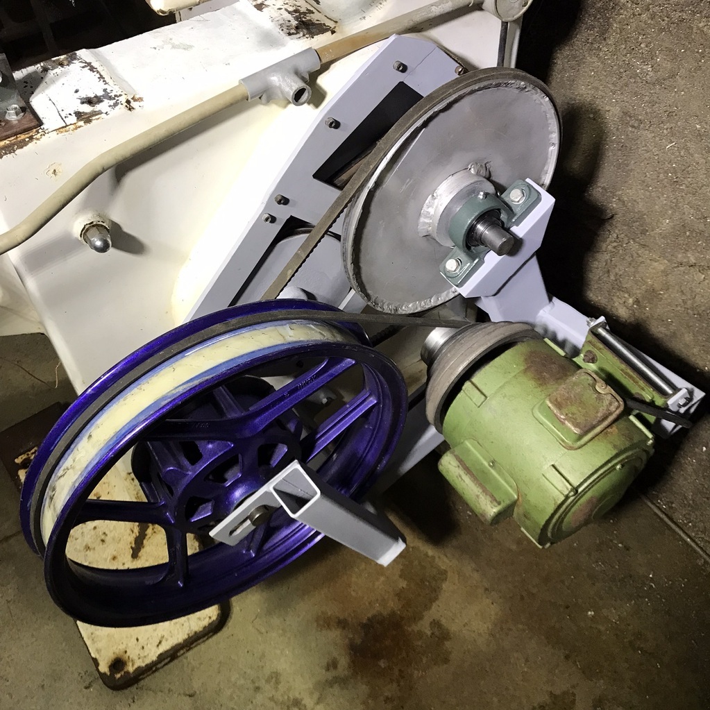 And the saw 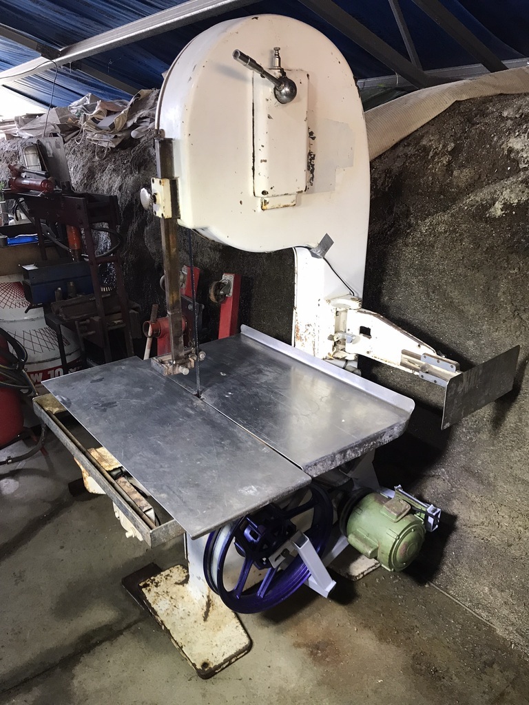 It works,but amazingly hasn’t been used on an actual job yet. Thanks for looking. This post is way too long. Real Triumph content soon. |
| |
|
|
|
|
|
|
|
Oct 15, 2022 11:39:59 GMT
|
|
|
| |
|
|
|
|
|
Oct 15, 2022 13:15:13 GMT
|
Yep, watching with great interest here too! Fantastic stuff!  |
| |
1968 Mini MkII, 1968 VW T1, 1967 VW T1, 1974 VW T1, 1974 VW T1 1303, 1975 Mini 1000 auto, 1979 Chevette, 1981 Cortina, 1978 Mini 1000 1981 Mini City, 1981 Mini van, 1974 Mini Clubman, 1982 Metro City, 1987 Escort, 1989 Lancia Y10, 1989 Cavalier, 1990 Sierra, 1990 Renault 19, 1993 Nova, 1990 Citroen BX, 1994 Ford Scorpio, 1990 Renault Clio, 2004 Citroen C3, 2006 Citroen C2, 2004 Citroen C4, 2013 Citroen DS5. 2017 DS3 130 Plenty of other scrappers!
|
|
gazzam
Part of things
 
Posts: 746  Member is Online
|
|
Oct 19, 2022 20:18:29 GMT
|
The Triumph has a bad clutch shudder and I think it’s made worse by the engine mounts. They are really soft and someone has coated the edges with black rtv to make them look a bit better. That really didn’t add much strength… 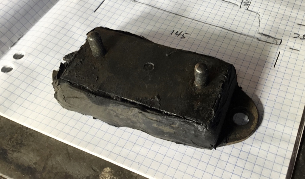 I couldn’t get originals, so I got a pair as close as possible in size, but it meant the chassis mounts needed to be modified. By modified I mean cut off and replaced. This is one of the originals in situ. 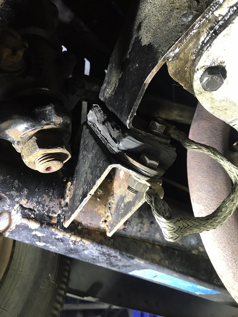 The new mounts including a part number for the record. 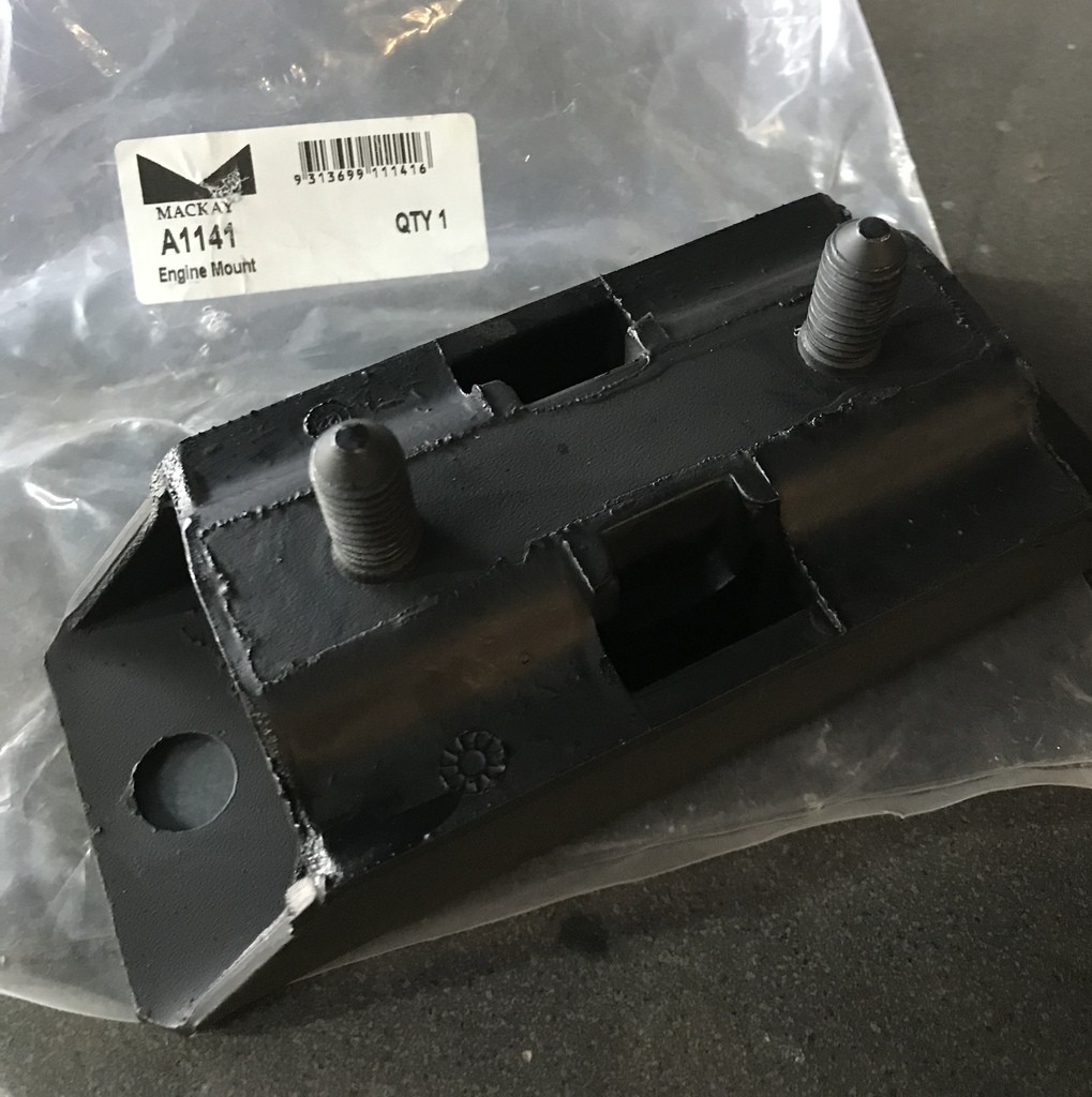 The new mounts had the same spacing on the top studs but I wanted to use bolts so I cut the studs off and drilled them out to suit the mounts on the engine. 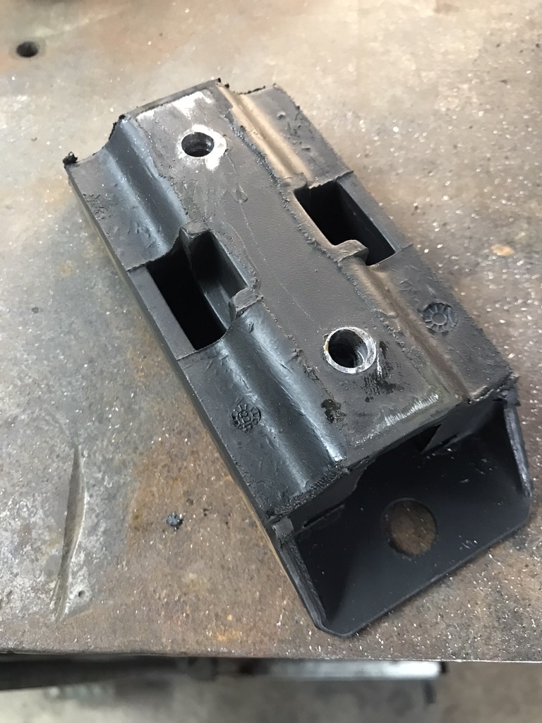 Propped up the engine and started cutting the old mount away. Here is the new mount bolted to the engine with the old mount mostly cut off. 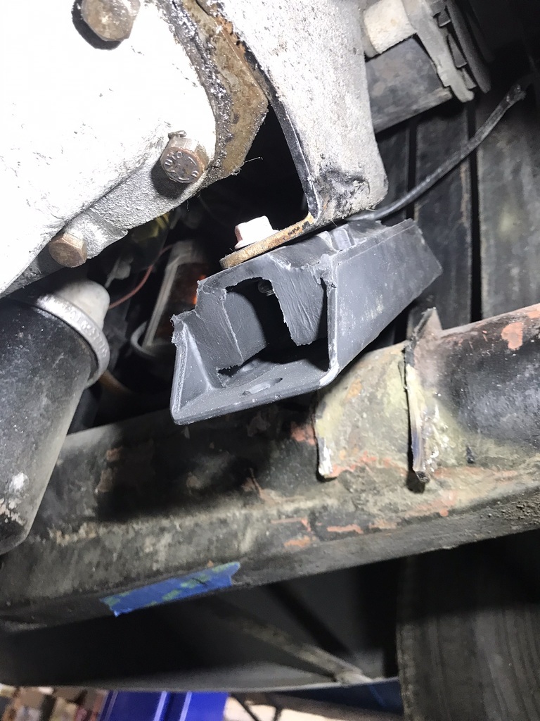 The chassis mount fully removed and tidied. 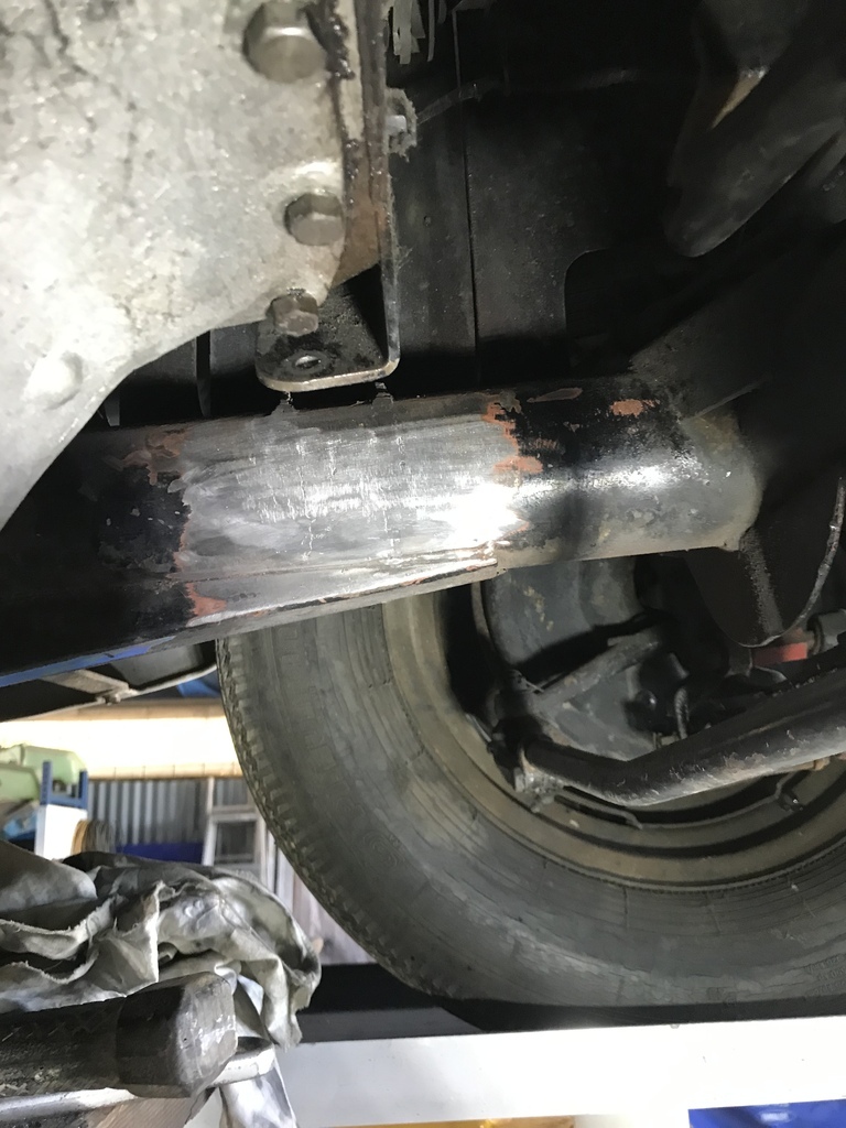 Cut a new chassis mount from a piece of rhs after making a cardboard template. 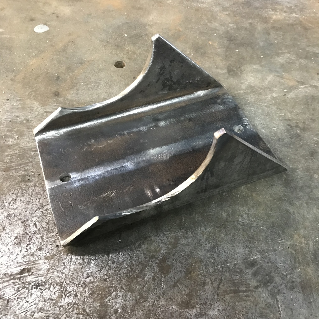 Tacked in place. 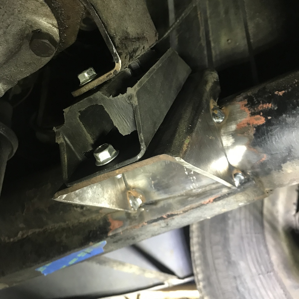 I got the other side to the same stage and then found that the board I had propping up the engine had allowed the whole thing to sag about 15mm. So I had to cut off both mounts and reshape them and then things worked out ok. One side welded as much as I can get to from the underside. 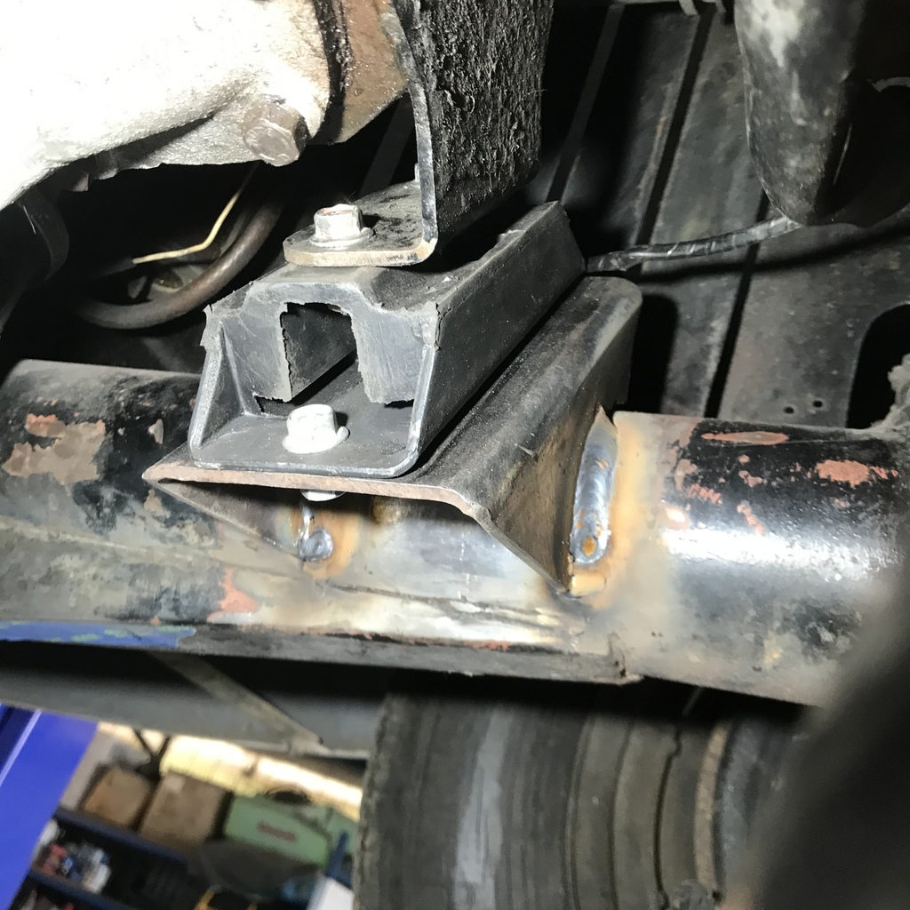 After a test drive, it is much better but still not cured. The rear/gearbox mount doesn’t look real flash either so I think it’s in for replacement also… The clutch will have to come out to fix it 100%. |
| |
|
|
|
|
|
|
|
I was looking at the chassis pics, wondering how it was constructed. Never come across square boxing on a round tube frame before. Didn't realise these were underslung cars either. 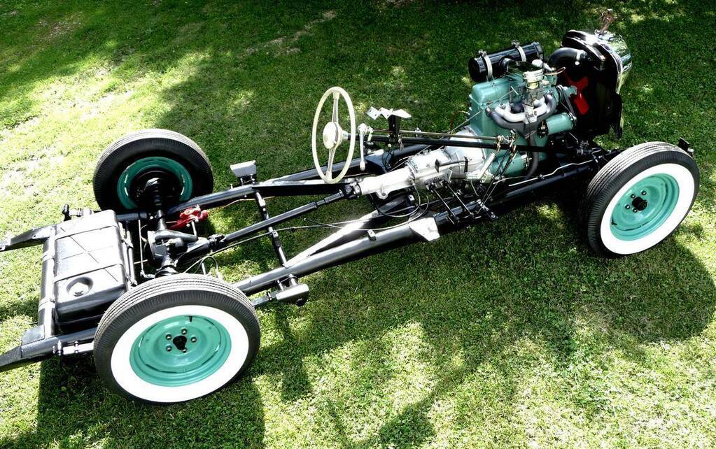 |
| |
|
|
Davey
Posted a lot
   Resident Tyre Nerd.
Posts: 2,350
|
|
|
|
|
It might just be my eyes or remnants of welds but it does look like you might have some hairline cracks in the chassis?
Really enjoying this project so far!
|
| |
K11 Micra x3 - Mk3 astra - Seat Marbella - Mk6 Escort estate - B5 Passat - Alfa 156 estate - E36 compact
Mk2 MR2 T-bar - E46 328i - Skoda Superb - Fiat seicento - 6n2 Polo - 6n polo 1.6 - Mk1 GS300
EU8 civic type S - MG ZT cdti - R56 MINI Cooper S - Audi A3 8p - Jaguar XF (X250) - FN2 Civic Type R - Mk2 2.0i Ford Focus - Mercedes W212 E250
|
|
gazzam
Part of things
 
Posts: 746  Member is Online
|
|
Oct 20, 2022 10:40:30 GMT
|
Back on the brakes. I noticed that the brakes seemed to be dragging, the car would barely roll on a slope. So I pulled the brake drums off for a look, thinking they must be adjusted too tight. Was quite surprised to find there are no adjusters. Front brake: 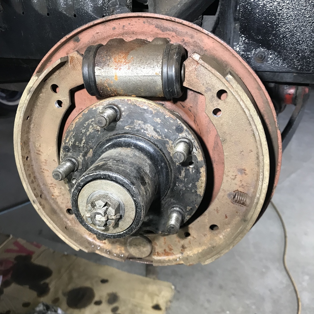 Rear brake: 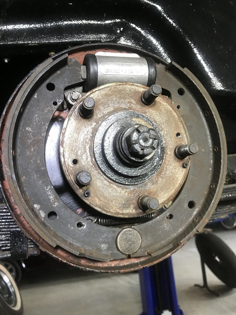 As you can see, no adjustment possible. WTF? as they say. I suppose it’s to do with the displacement style master cylinder setup it had originally. So I removed the cylinders and they were all pretty manky. They weren’t retracting as well as you would like. The rears cleaned up nicely with a hone, being aluminium. But the fronts were pitted ( steel ) so I sent them off to be resleeved along with the ex Jag master cylinder as it has been leaking. On each brake the shoes ( front and rear ) have only one small return spring situated just near the pivot. And each cylinder has a spring between the cups (seals) to push them apart. I read somewhere that in the original design the shoes were meant to be in light contact with the drums. Given that each brake has a leading shoe, I can’t see how the servo effect won’t be a problem. The car is underpowered and doesn’t need a further load, by having the brakes drag. So my plan is to add some stronger return springs. The shoes are in good shape, so I don’t think this will be a problem with too much pedal travel. I am flying blind here, so if anyone has any advice or warnings, I’m all ears. So in the meantime, while waiting on the cylinders to be sleeved, I’ll make a start on mounting the supercharger. I wanted better access, so decided to remove the radiator. I’m liking this car more now. The bonnet comes off with four screws. Then two nuts under the rad and the two long struts between it and the cowl. Then the rad and grille can be lifted out. 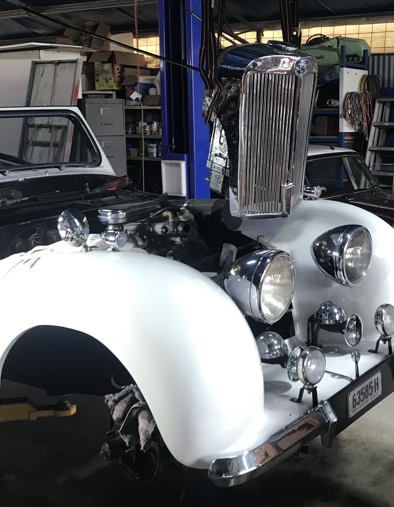 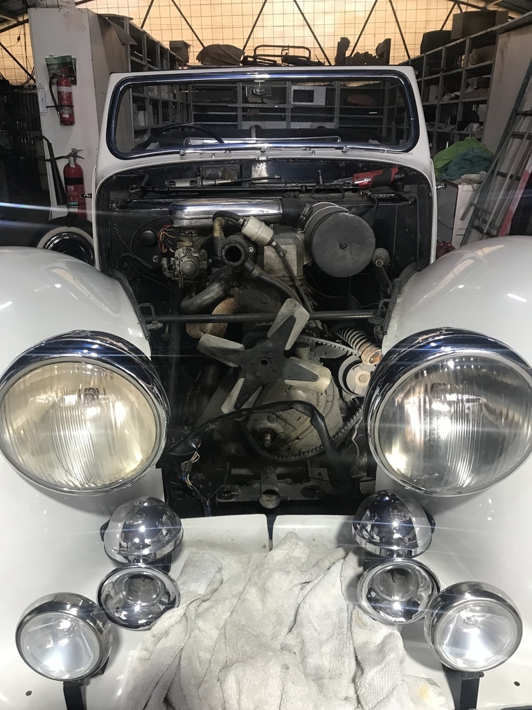 All cars should be so simple. That’s where I’m up to, more later. |
| |
Last Edit: Oct 25, 2022 10:18:39 GMT by gazzam
|
|
|
|
|
Oct 20, 2022 19:40:40 GMT
|
|
it probably had some sort of residual pressure device in there which kept a couple of psi in the brake line, I'd be inclined to see If I could engineer some sort of adjuster in there, some sort of snail one would work well, perhaps with a bit of filing to the end of the shoe you use a morris minor one which sits between the shoe and the cylinder.
(you'd also need to drill a small hole in the drum or backplate to access it as well)
|
| |
Last Edit: Oct 20, 2022 19:41:55 GMT by kevins
|
|
gazzam
Part of things
 
Posts: 746  Member is Online
|
|
Oct 25, 2022 10:17:37 GMT
|
Made a start on the forced induction side of things, while I’m waiting for the brake cylinders to be sleeved. First the drive. This is the crankshaft pulley in position. I need to piggyback a bigger diameter pulley to this somehow. 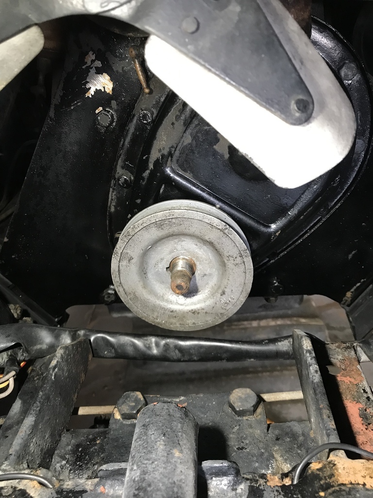 Here’s the original crank pulley, showing the face that my pulley will have to sit up against. 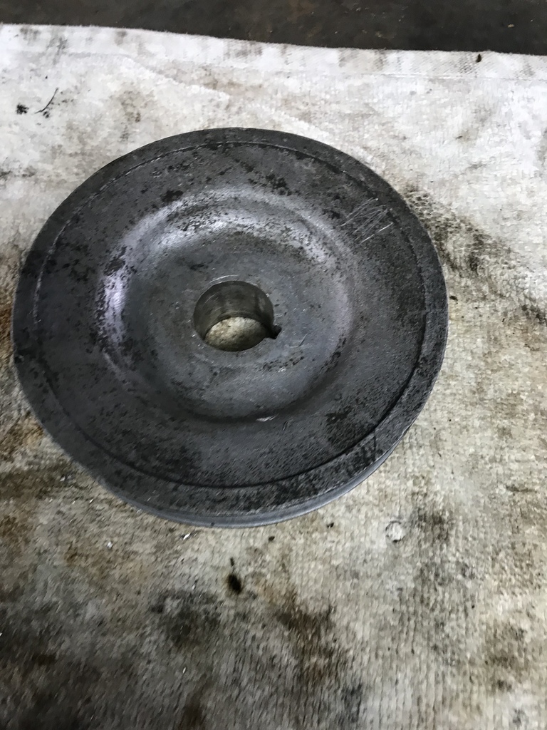 To make the hub I tried pressing a big dimple into a piece of 1/8” sheet but as I expected it wasn’t possible with my press. This should work though, made it in two pieces and weld them together. 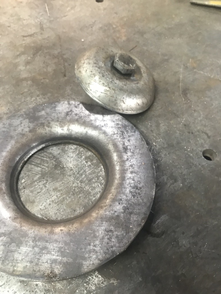 Like this. 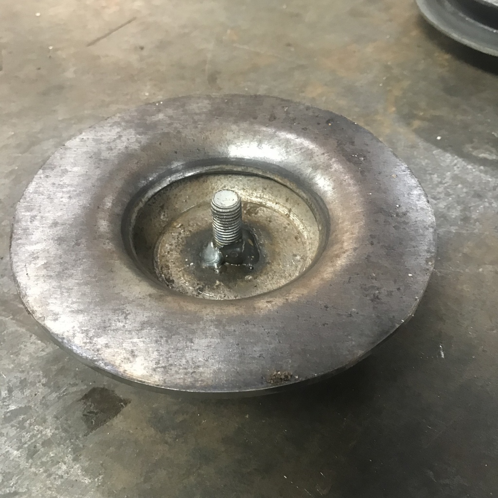 That will be the hub, I need to make from steel to get enough strength given the thickness I’m limited to. The outer part will be aluminium. The bolt is welded in there so I had something to mount in the lathe chuck. Time to melt some aluminium. 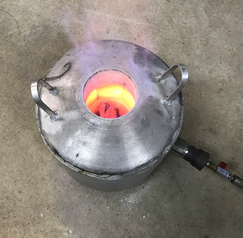 It took me four goes to get a blank that was ok to make the vee part of the pulley. First try. 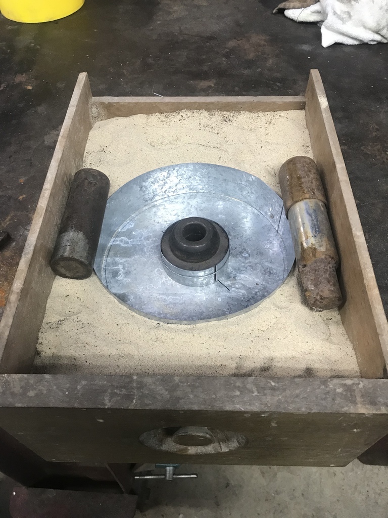 Sand in a box with the sheet metal mould on a piece of tin. That didn’t work because the tin buckled. So I tried making a green sand mould. 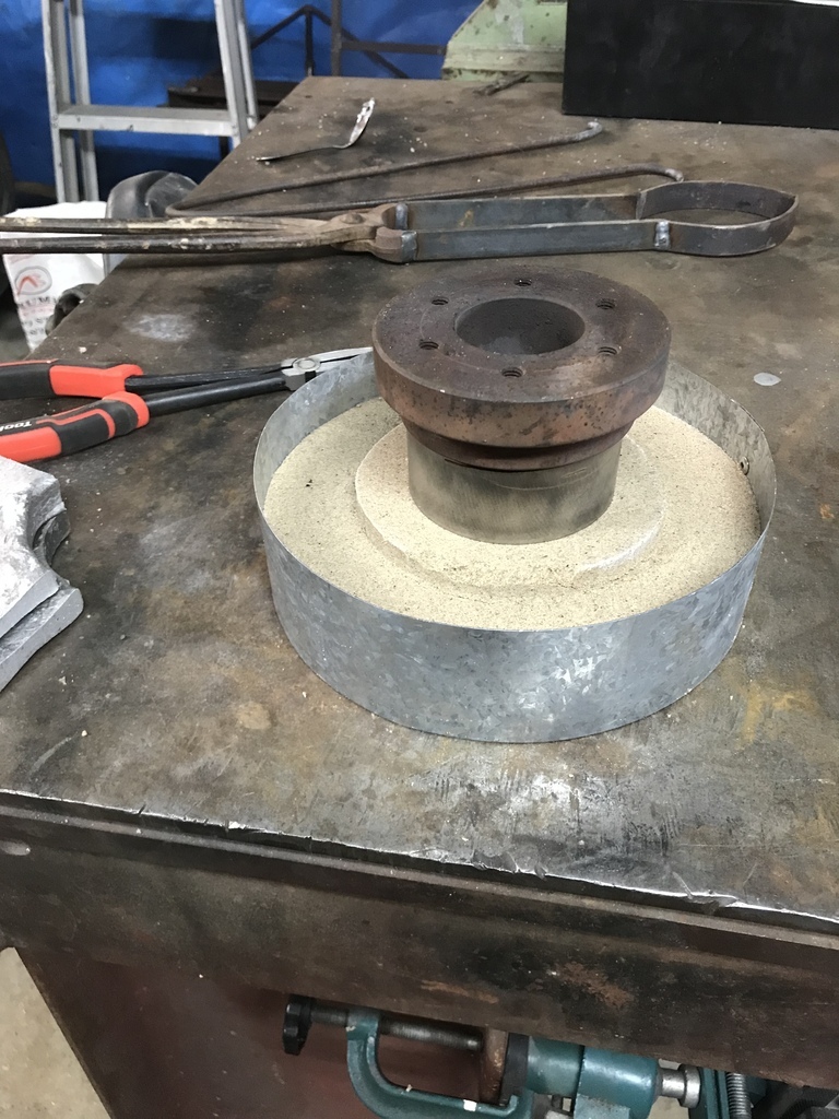 That didn’t work because the moisture in the sand caused bubbles. Don’t know why I expected otherwise really. Don’t know how anyone gets this to work. The next one failed because I used a half inch thick base and that cooled the ally and it didn’t flow out properly. So the next one used an old shrinking disc as a base and it worked. 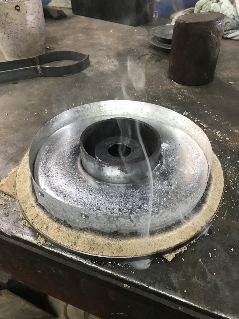 And the result. Glad it finally worked, I was growing tired of cutting up and remelting the ally! 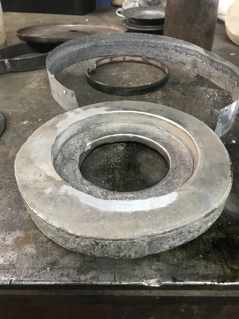 One side pretty close. 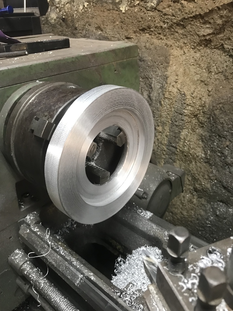 And the other side underway. 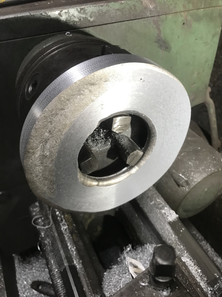 Vee groove cut. Sanded with some 240 grit and ready for the next stage. 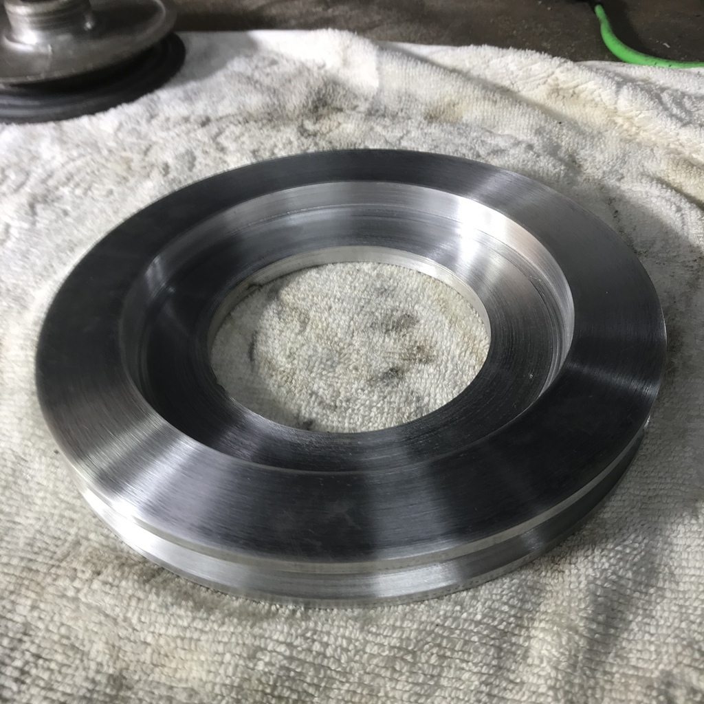 Thanks for looking. |
| |
|
|
gazzam
Part of things
 
Posts: 746  Member is Online
|
|
Oct 26, 2022 15:18:37 GMT
|
Making a pulley continues. Bolted the welded up hub into the aluminium outer piece. Then trued up the face and bored a hole. 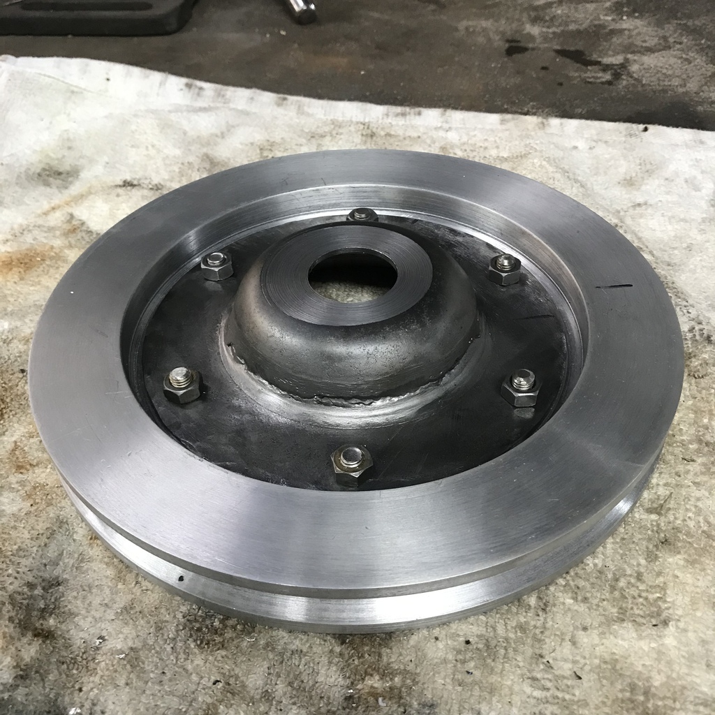 Only problem was that the hole was too big because I hadn’t checked where the crank pulley came to on the crankshaft. So I decided to cut the centre out of the hub and make version two. Press a piece of 1/8” 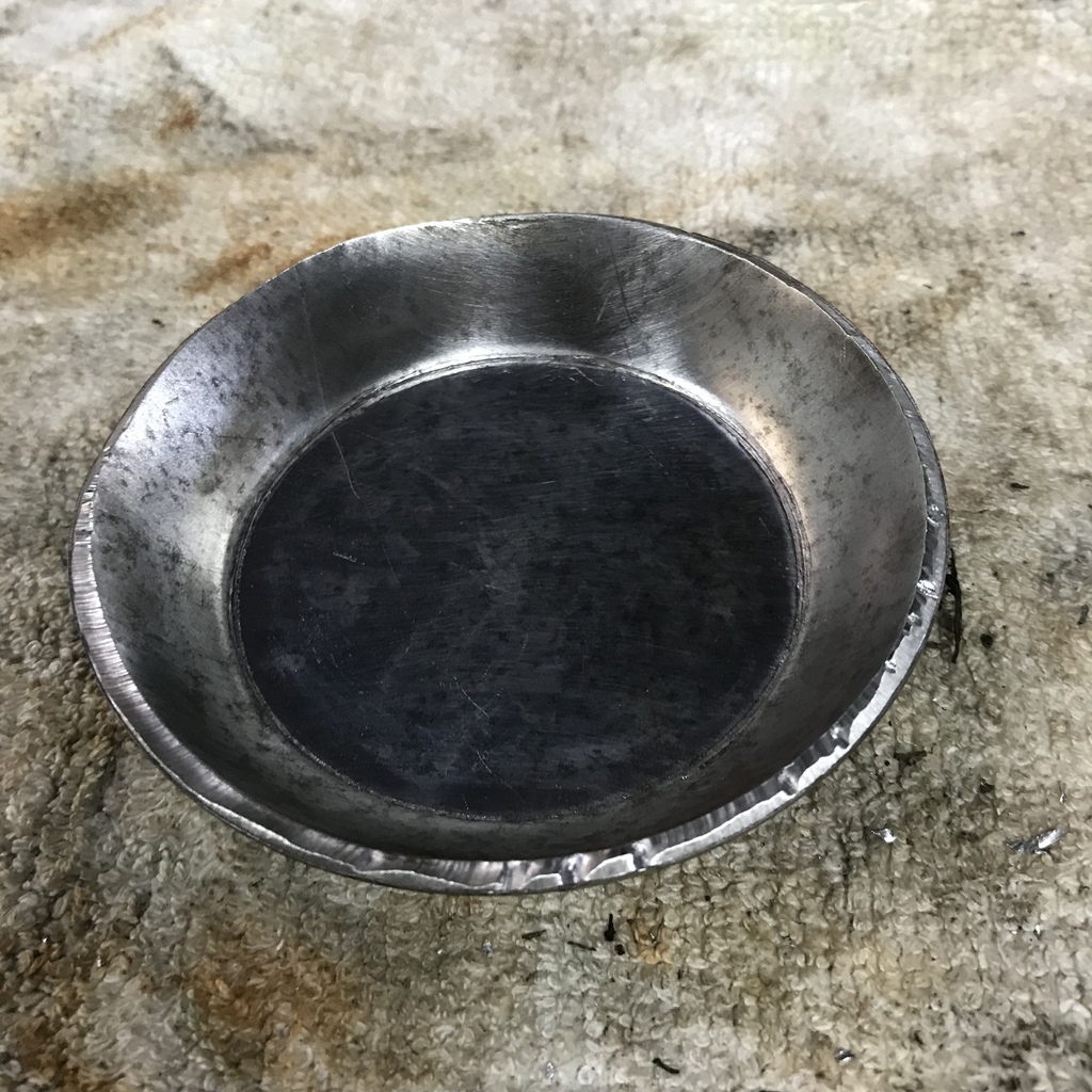 Then cut the centre out. 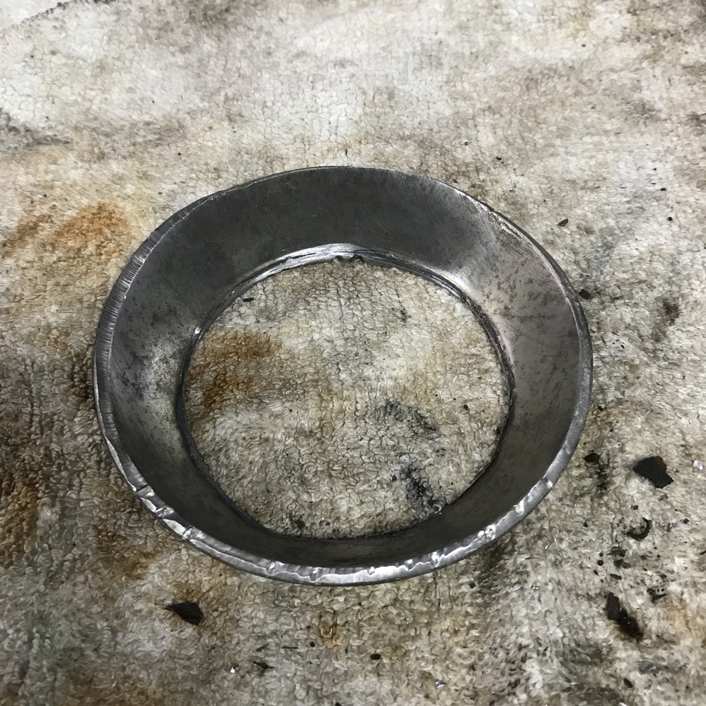 Welded a disc of 5mm plate into it, then weld it back into the other disc to complete the hub. Trued the face and bored the correct size hole. 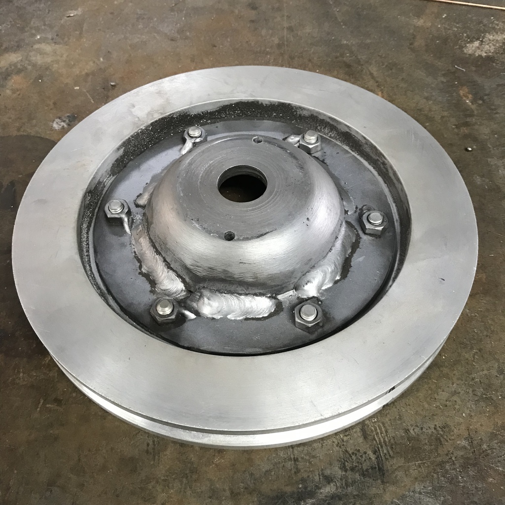 Here’s how the original crank pulley sits on the new one. 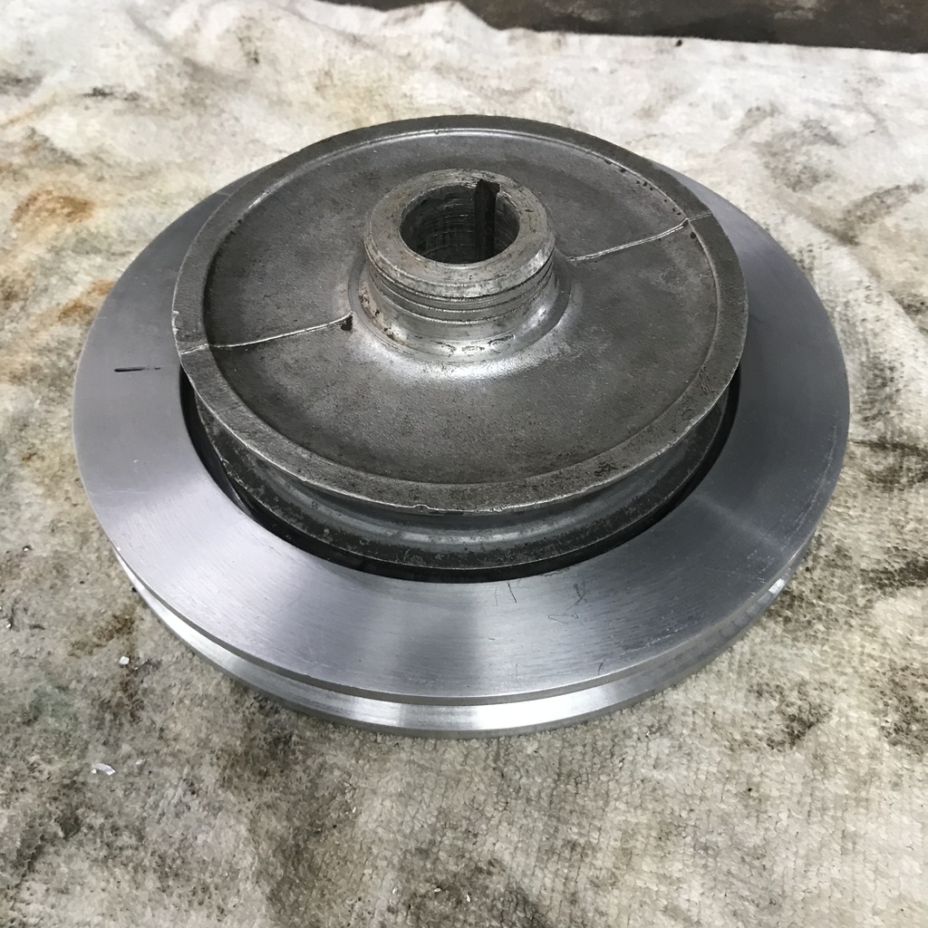 Mounted it in position and drilled a pair of holes to fit drive pins. They’re welded to the steel hub and engage in holes in the original pulley. 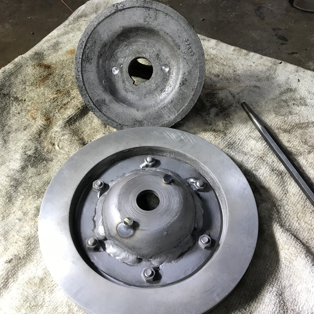 Finished, other than bending over the tab on the lock washer. 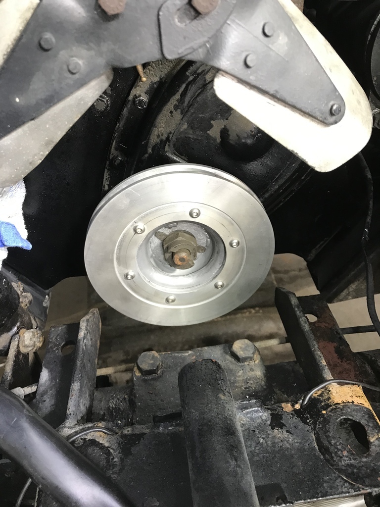 Thanks for looking. If you spot any potential problems, don’t be shy. Coming soon…brackets! |
| |
|
|
|
|
|
|
|
|
|
|
Sounds like your green sand was a bit too moist. Also, did you put gas vents in and are you degassing the melt?
Liking the way you are engineering this.
|
| |
Proton Jumbuck-deceased :-(
2005 Kia Sorento the parts hauling heap
V8 Humber Hawk
1948 Standard12 pickup SOLD
1953 Pop build (wifey's BIVA build).
|
|
gazzam
Part of things
 
Posts: 746  Member is Online
|
|
Oct 28, 2022 17:23:53 GMT
|
No vents Crockpot, it was open on the top. Also have never degassed the melt, not aware of that. Agree that the sand was probably too moist. As promised…bracketry. With the radiator out of the way and the car lifted a couple of feet, access is a delight. Not often that can be said with any car in my experience. The right hand front engine plate was the obvious place for the supercharger bracket. Made a cardboard template and transferred it to a piece of 5mm plate. Picked up 3 existing holes and added one more. I discovered that great tradition of the previous restorer continues. The two bolts that I removed, while the same size and thread, had different markings. Boy that gets on my goat. But I have to admit he’s consistent - no two fasteners shall be the same! 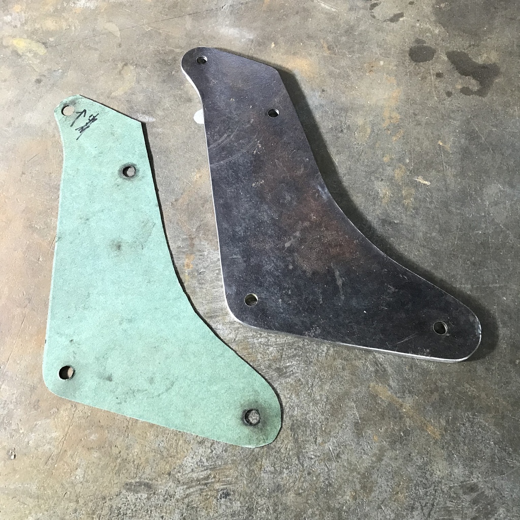 Used a folded up rag to support the s/c in its approximate position. Just enough room. 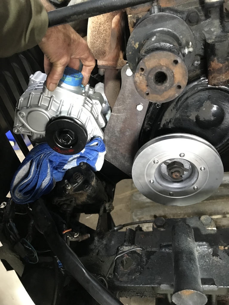 Cut out a pair of lugs from the same plate. These will be the main supports. 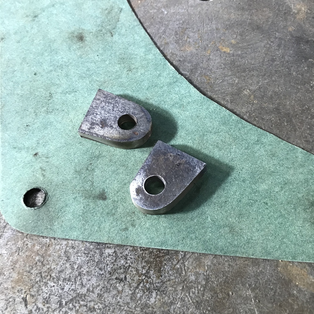 Welded them to a short piece of 5mm flat. 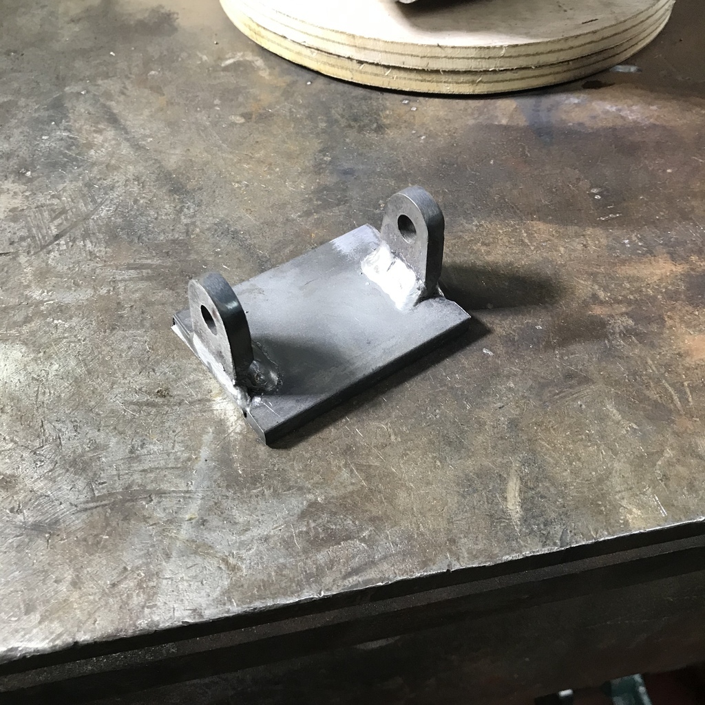 After bolting up the main plate I tacked a piece of angle to it. 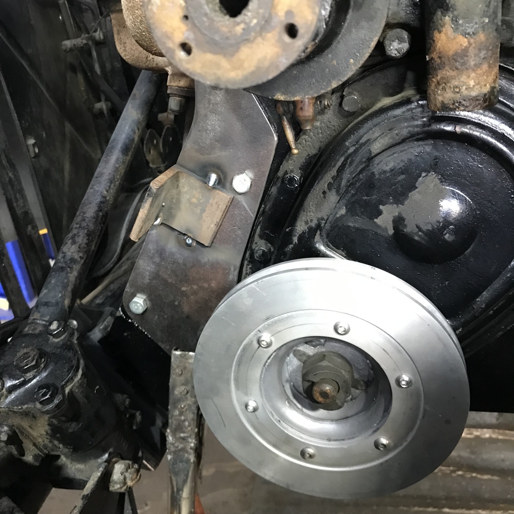 After attaching the small bracket to the s/c, it was the clamped to the angle. The pulleys were then able to be lined up. 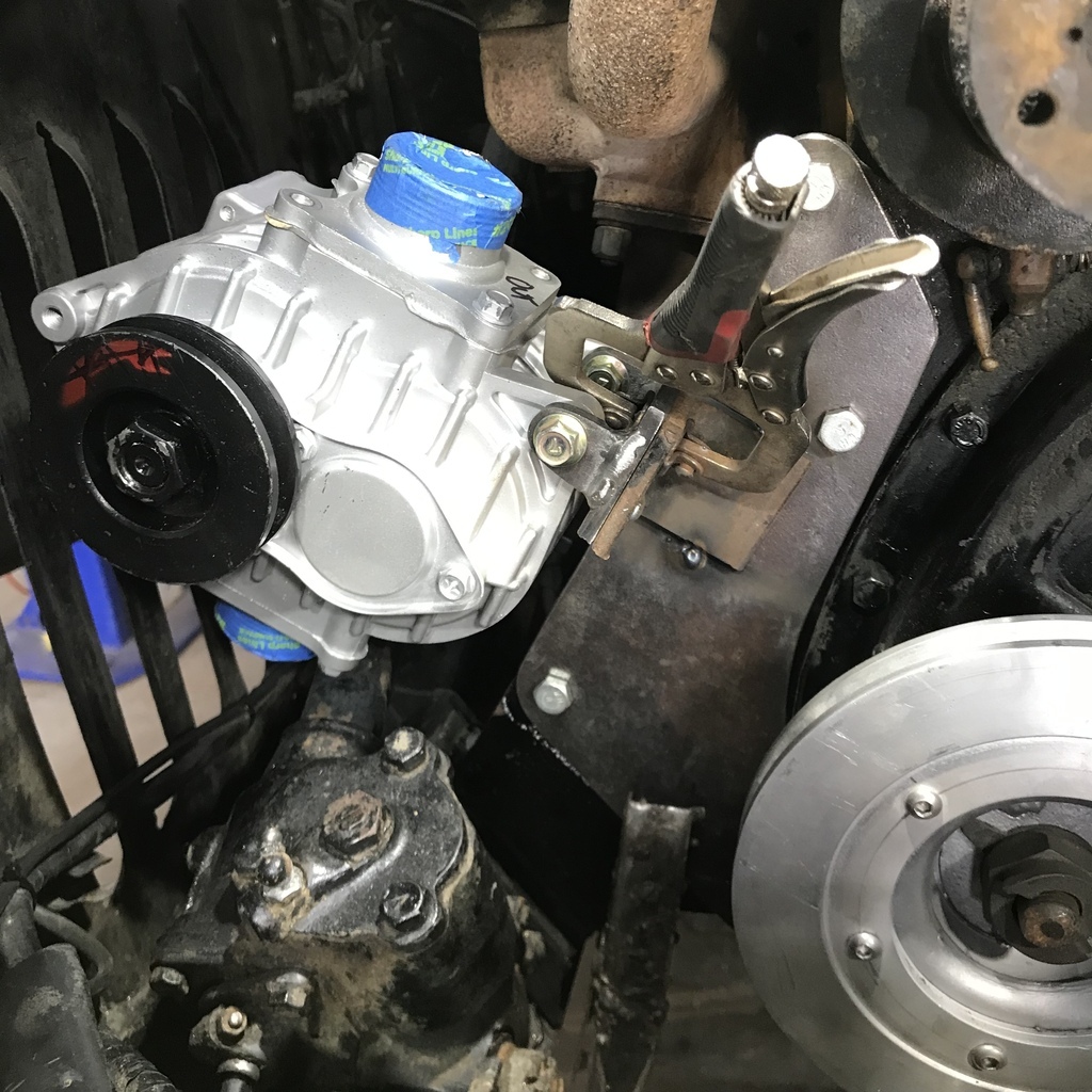 I made another piece to pick up three of the inlet flange bolts on the underside of the s/c.This will effectively lock it in position so a belt tensioner will be needed. But it means I can avoid any flexible joints in the plumbing. Once all the bits were tacked securely, the whole lot was removed to the bench for welding. Also added some gussets. This surprisingly gleaming thing ( must be the light ) is the result . 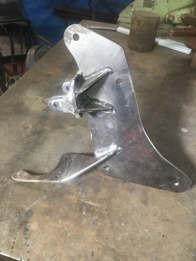 And the pump ( it’s so little it seems a bit of overstatement to call it a supercharger) is mounted. 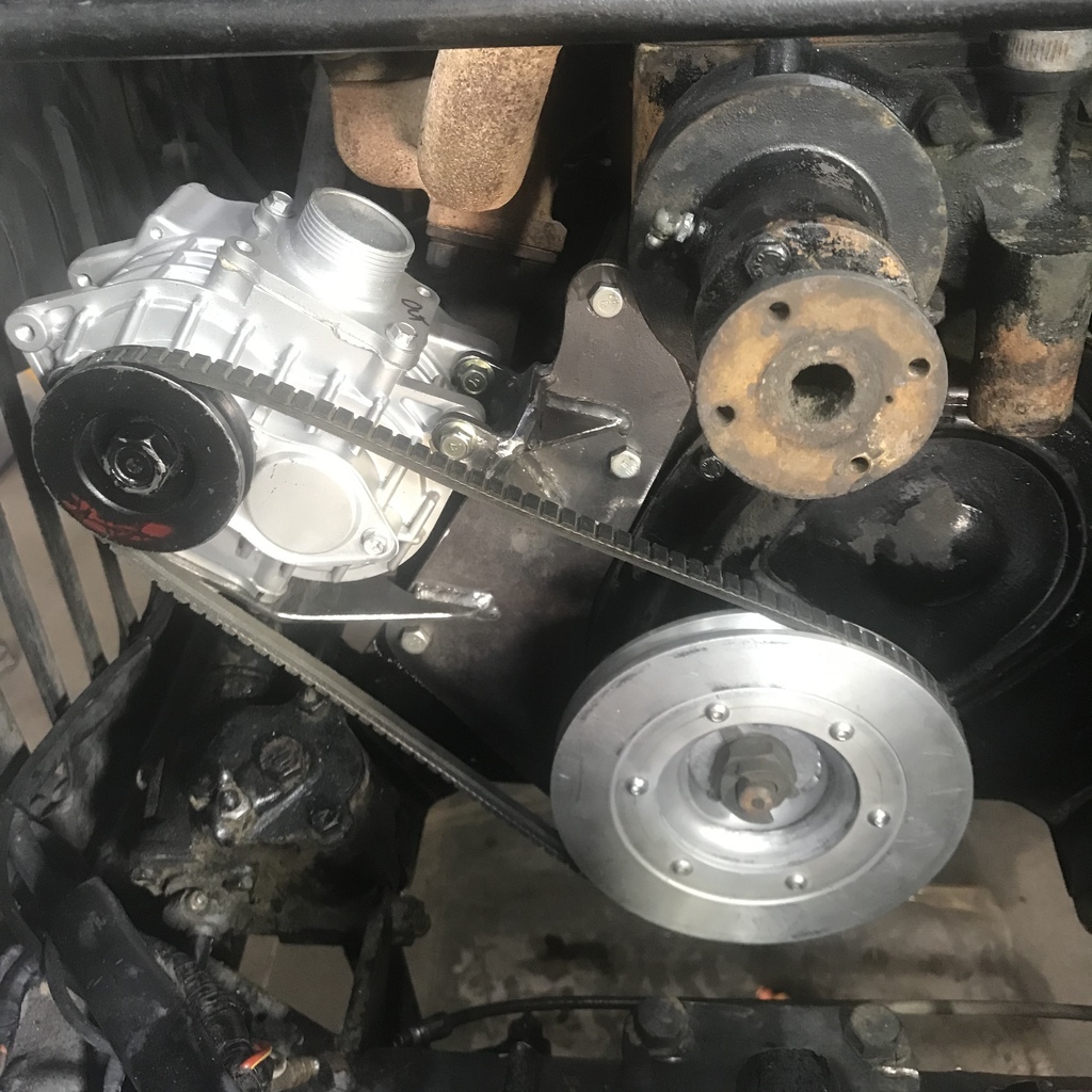 I had taken the tape off the ports in order to give it a brief test spin, just to check that the rotation was correct. There was some grin factor involved. Next I need to work out a belt tensioner and get some tube ordered to connect the holes. Thanks for reading. |
| |
|
|
|
|
|
Oct 28, 2022 21:44:34 GMT
|
|
Nice work, as always 🙂
Nick
ps. Good to see you are not underwater as quite a bit of the south eastern corner seems to be. Was hoping the sun would be out for my visit next week but it’s not looking very certain….
|
| |
Last Edit: Oct 28, 2022 21:46:45 GMT by vitesseefi
1967 Triumph Vitesse convertible (old friend)
1996 Audi A6 2.5 TDI Avant (still durability testing)
1972 GT6 Mk3 (Restored after loong rest & getting the hang of being a car again)
|
|
|
|
|
Oct 28, 2022 23:16:47 GMT
|
|
Can't wait to see how this pans out.
|
| |
|
|
logicaluk
Posted a lot
   Every days a school day round here
Posts: 1,373
|
|
|
|
|
Wow, I love RR people. Casting your own pulley, top marks.
Carry on.
Dan
|
| |
|
|
CaptainSlog
Part of things
 
Posts: 510
Club RR Member Number: 180
|
|
|
|
|
Love this little car, never even knew they existed. The engineering you are doing is amazing - will be following this for sure! Most would have thrown an MX5 or Honda engine at it, you are (hopefully) immproving on what was there. Try Morris Minor or Beetle adjusters in the brakes.
|
| |
|
|
75swb
Beta Tester
Posts: 1,052
Club RR Member Number: 181
|
|
Oct 29, 2022 22:44:50 GMT
|
|
How I'd managed to miss this for so long is a mystery! Fantastic work and a cool little car
|
| |
|
|
gazzam
Part of things
 
Posts: 746  Member is Online
|
|
|
|
Thanks for the kind words. Belt tensioner. Found a suitable sealed bearing in the stash. I wanted two, so of course, there was one. It is just tad narrow for the belt to run on, so I found a suitable piece of pipe to make a sleeve that is wide enough. Bored it out so the bearing is a nice press fit. 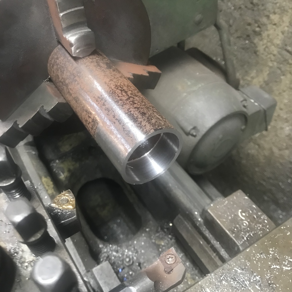 Tidied up the outside and parted it off. Here it is with the bearing. 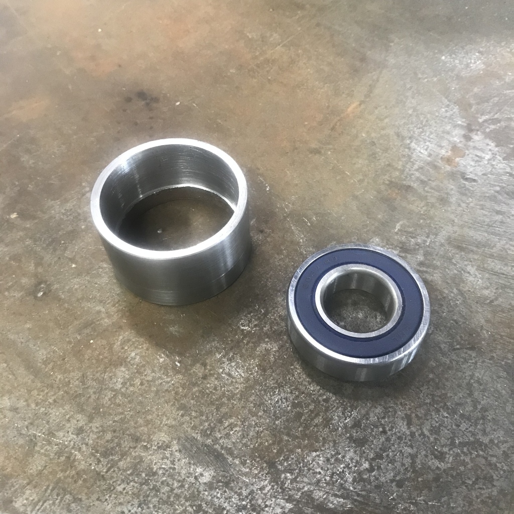 Turned down the end of a piece of 1” bright shaft to fit the bearing. And drilled and tapped the end with an 8mm thread. 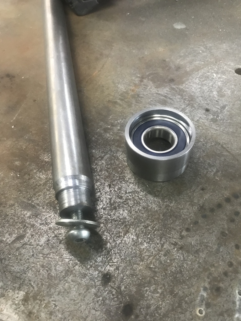 A couple of other bits of scrap, a hole to fit the shaft. 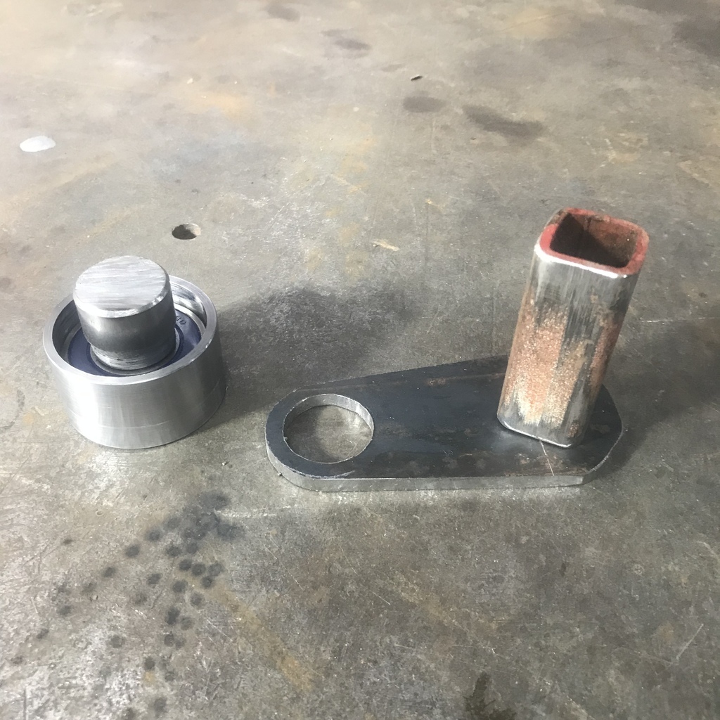 An adjuster cut from another scrap of flat. The curved slot was drilled and filed by hand. I couldn’t think of a simple way of milling it. 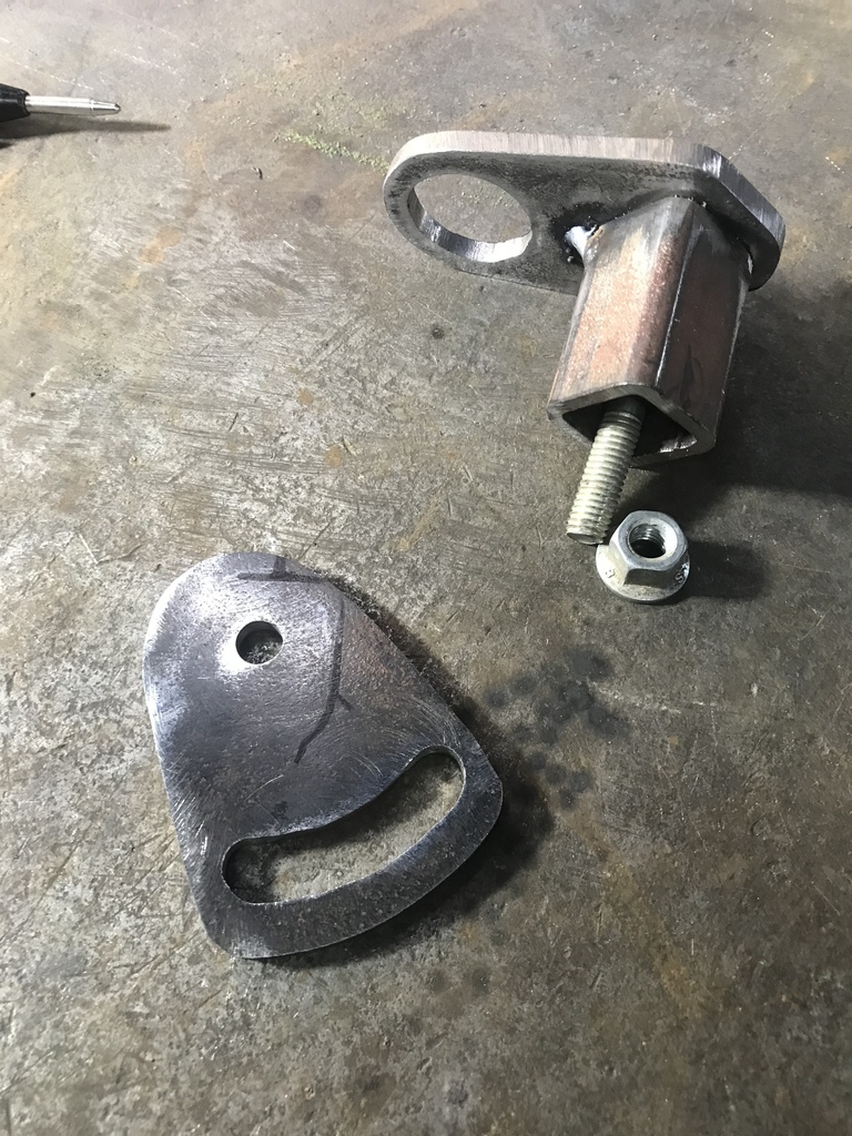 All the bits welded together and bead blasted. 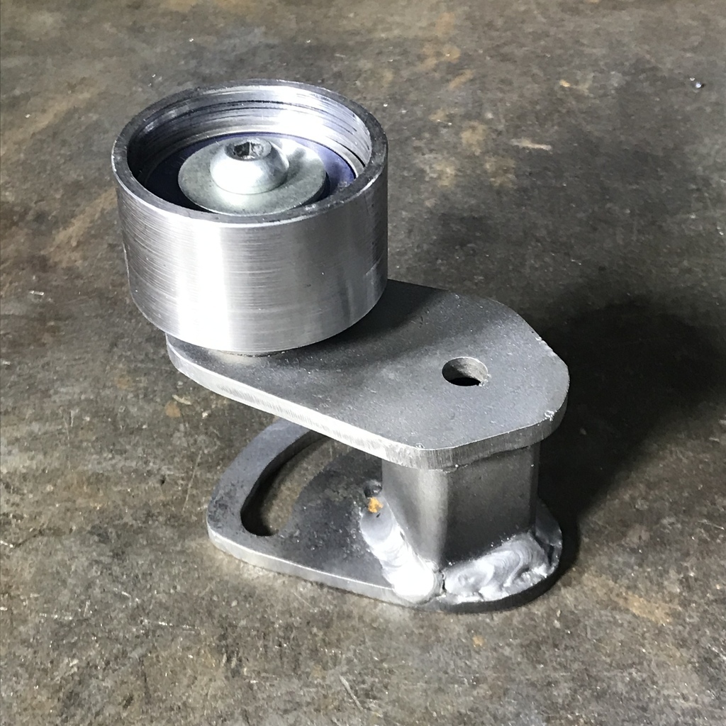 Used the mounting hole that I had drilled in the main bracket for the pivot and added one more for the locking point. 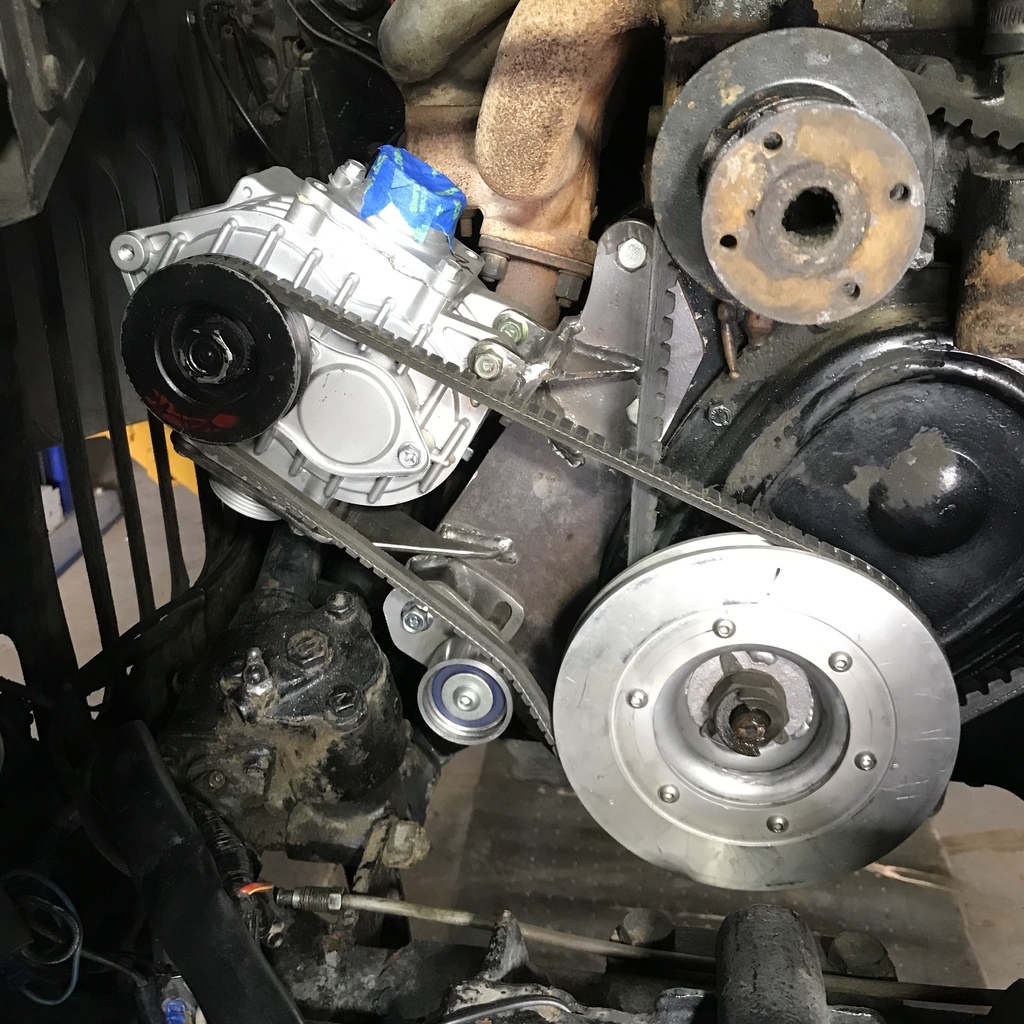 Thanks for looking. Always open to suggestions… |
| |
|
|
|
|
gazzam
Part of things
 
Posts: 746  Member is Online
|
|
|
|
Thanks horrido. I’m pleased how it turned out. I’d been trying to visualise tensioners with thread adjusters etc, when it finally dawned that it didn’t need to be so complicated. Made a start on the piping side of things. First though, the carb needed to have a place to be. It needed to be somewhere near where it was, so I can use the original air cleaner. So I cut a pair of aluminium flanges like this: 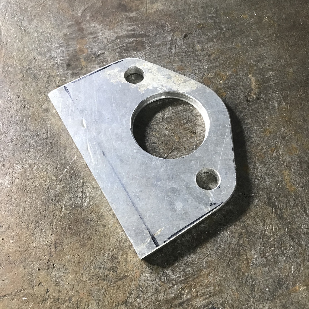 One of which will go on the inlet manifold where the carb was: 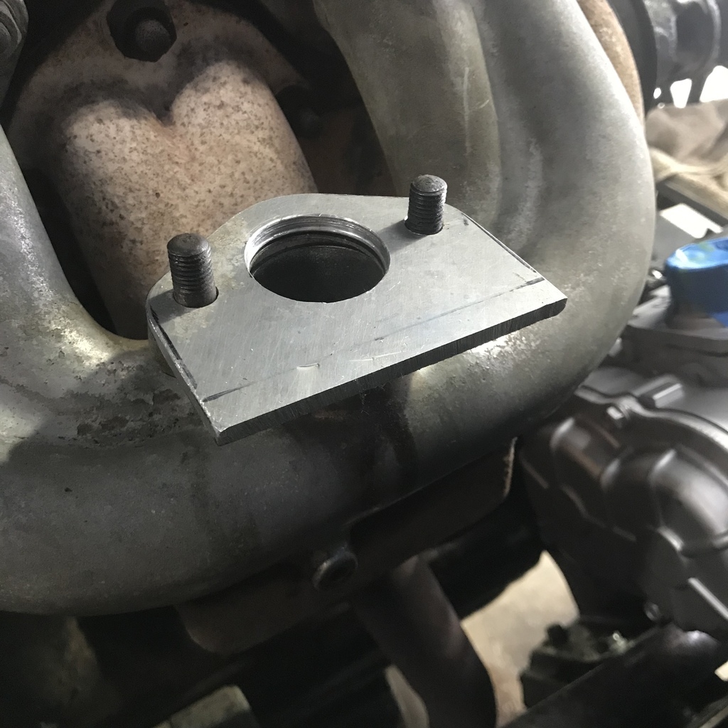 And the other, after a parallelogram shaped piece is welded between them, will hold the carb in its new location. Here they’re being tacked together. 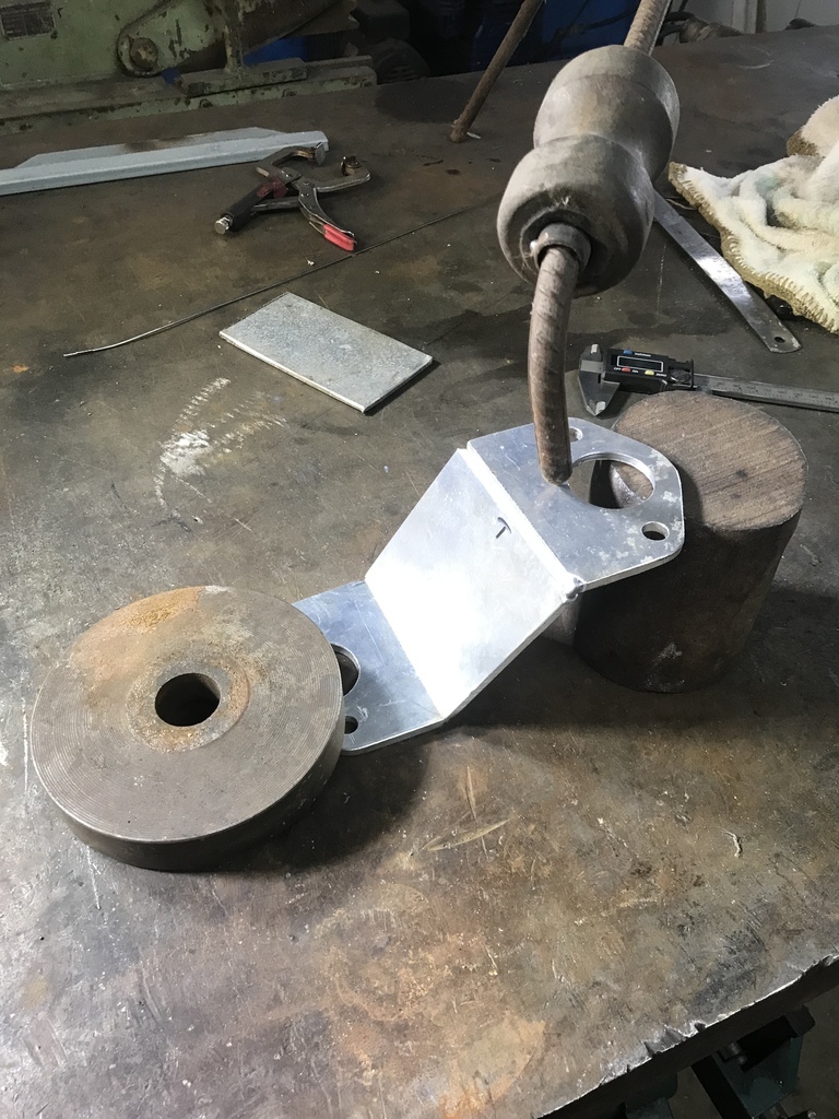 In place for a trial fit after tacking. 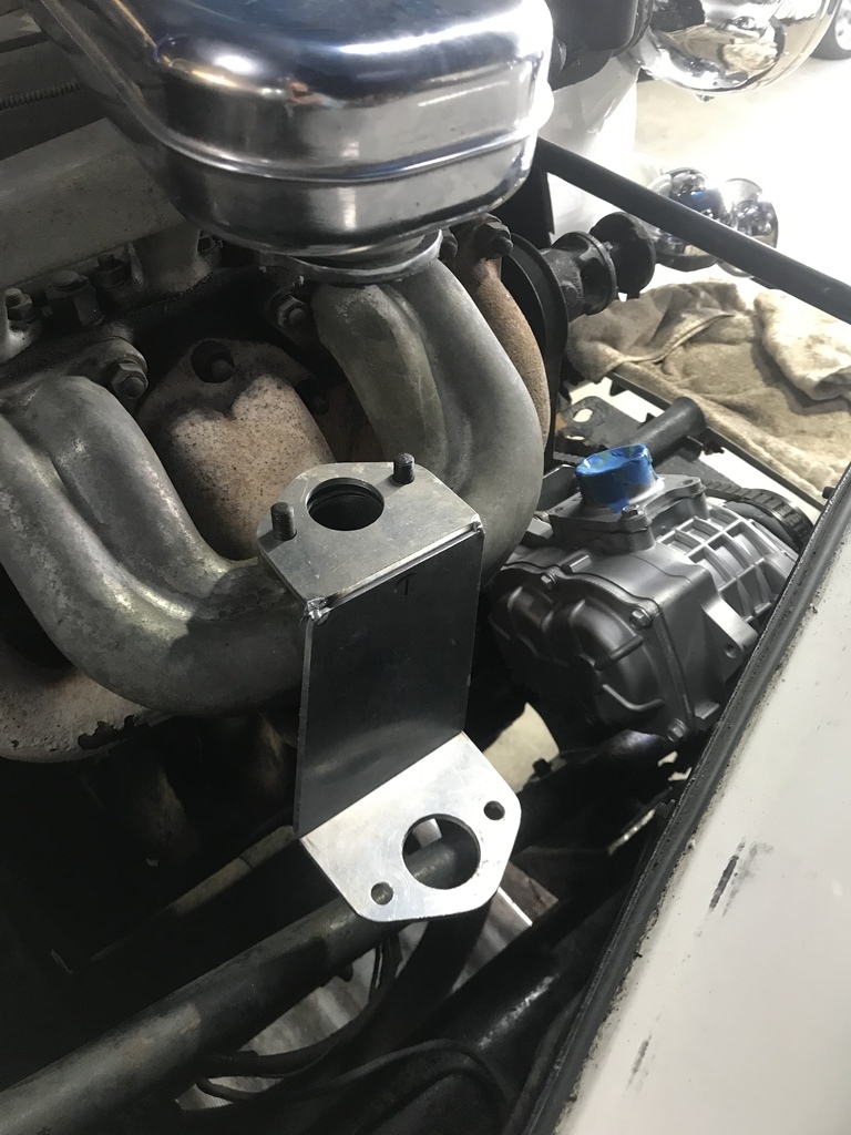 Welded and one gusset added. 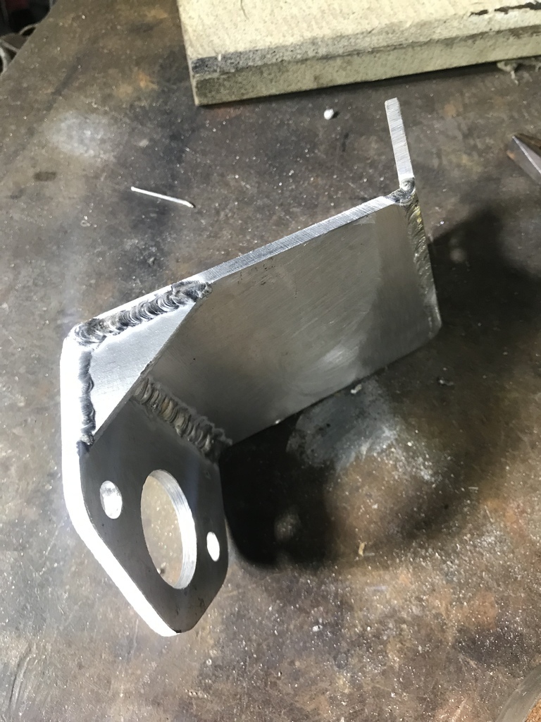 Now I need to add a gusset to the other side and make a lug on the back to pick up a tapped hole in the side of the inlet manifold. That should make it robust enough to hold the carb. Done and carb in place. 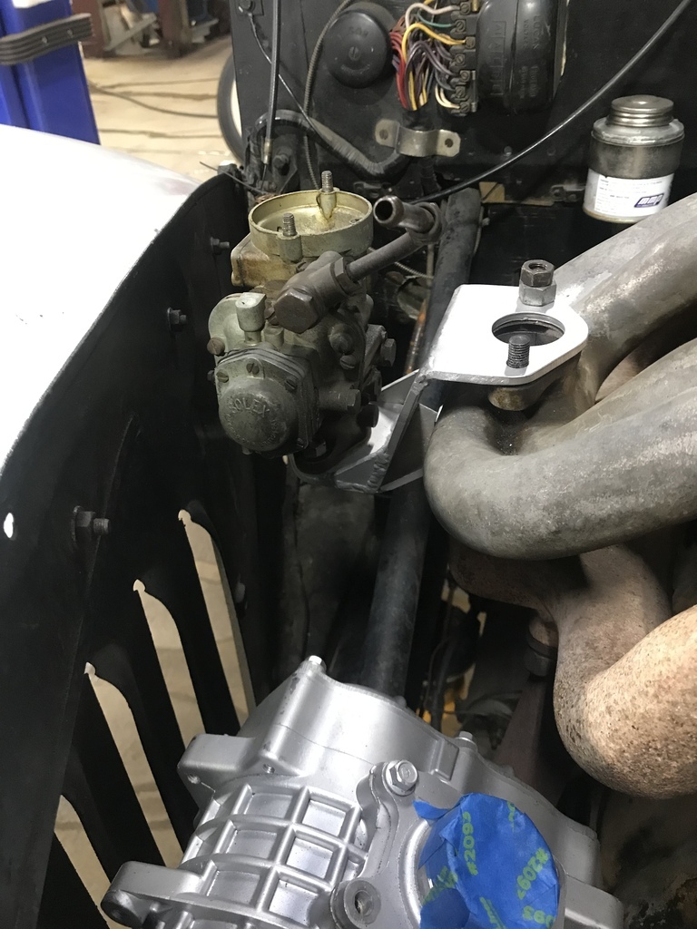 But, Houston we have a problem. I want to keep the original chrome thing that joins the air filter to the top of the carb. This chrome thing. 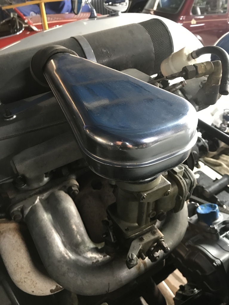 Due to a lack of planning I’ve ended up with it being very difficult to get a pipe from chrome thing to the top of the carb. Simply due to the angle. 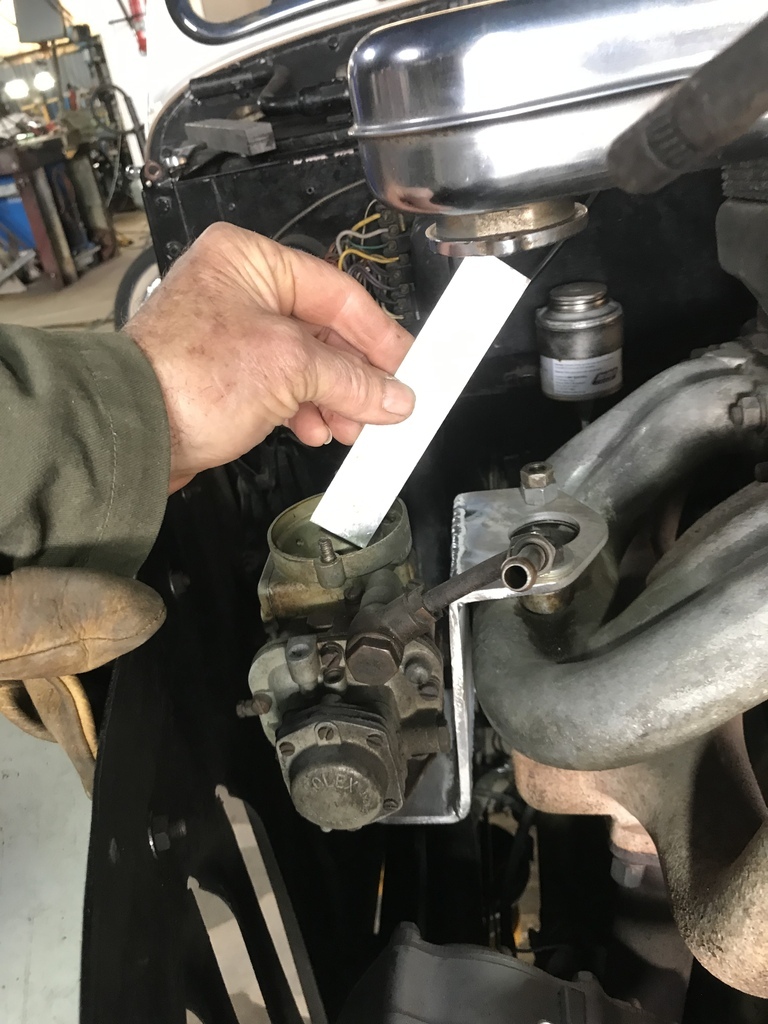 So I’ve altered the bracket to move the carb closer to the manifold, making the angle shallower. Not a big deal. Now the pipe is more doable. Thanks for looking. Suggestions for a name for the chrome thing welcome. Along with any other comments etc. |
| |
|
|
|
|


