|
|
|
Dec 17, 2011 17:50:50 GMT
|
Christmas bonus came in, going to buy this little beastie: 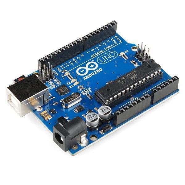 ( www.sparkfun.com/ ) Gotta learn how to program it, but it will make a nice standalone / interface for the car. I really need to move the car up here- this might be the point where I can convince SWMBO I need to insure, test and plate it.  --Phil |
| |
Last Edit: Dec 31, 2011 2:02:40 GMT by PhilA
|
|
|
|
|
|
|
Dec 17, 2011 20:44:17 GMT
|
|
What this does???
I might buy one for my lancer...
|
| |
|
|
|
|
|
Dec 17, 2011 21:11:37 GMT
|
What this does??? I might buy one for my lancer... Universal programmable input/output board. I bought a small LCD screen for it (think small cellphone screen) and it should be man enough to preform the calculations I need of it on the fly. It runs at 16MHz, which is 4 times as fast as an original IBM PC lol It should make a nice standalone interface to plug in and display information about the car, and also has the option to plug into a PC and push computed information across. Conversely, it is expandable to include SD card storage so that's a possibility too. You'd have to know the output data format to be able to write a program for the Lancer, but technically it would be possible  --Phil |
| |
|
|
|
|
|
Dec 17, 2011 23:19:11 GMT
|
|
Thanks for the free knoledge...
|
| |
|
|
|
|
|
Dec 23, 2011 18:39:09 GMT
|
Got the little board in, along with a display made for it. 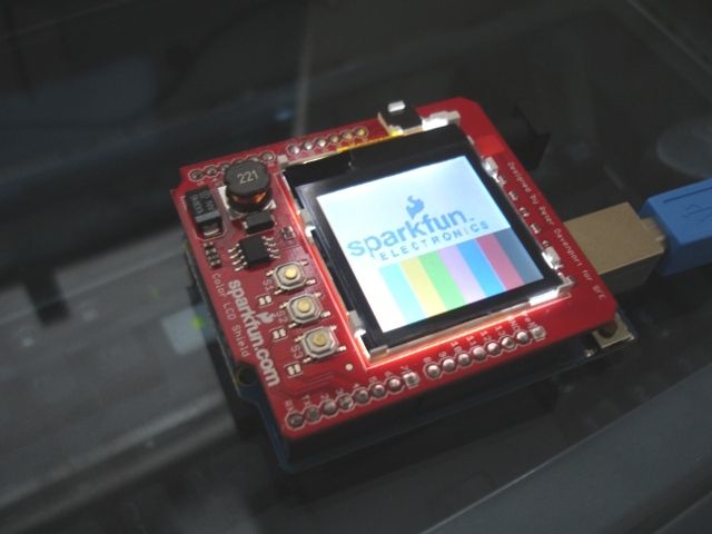 It's pretty cool, though the screen I got has a bad contact so that's going to have to go back for a replacement when the place opens up agains after Christmas. To give you an idea, that is really quite tiny- 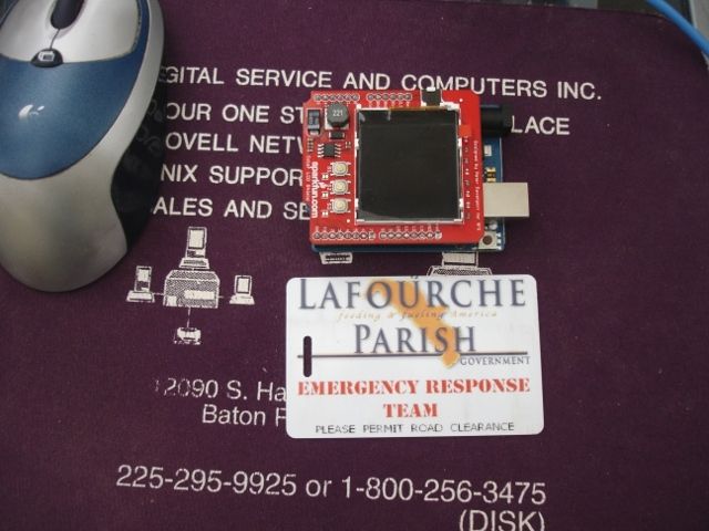 That's my hurricane card, same size as a regular credit card. In a box, this should fit quite happily in the palm of your hand and not get in the way in the car. It has USB out so the thing can output to a computer which can act as a slave device and display the output directly to a larger screen and act as a data logger. It also uses a derivative of the programming language C. I'm pants at writing the code for it but someone I know has adopted this as a project and is helping out writing stuff that works  To give you an idea, to display that test pattern, this is needed to make it work: */
#include <ColorLCDShield.h>
LCDShield lcd;
int buttons[3] = {3, 4, 5}; // S1 = 3, S2 = 4, S3 = 5
byte cont = 40; // Good center value for contrast
void setup()
{
for (int i=0; i<3; i++)
{
pinMode(buttons, INPUT); // Set buttons as inputs
digitalWrite(buttons, HIGH); // Activate internal pull-up
}
lcd.init(PHILLIPS); // Initialize the LCD, try using PHILLIPS if it's not working
lcd.contrast(cont); // Initialize contrast
lcd.clear(WHITE); // Set background to white
lcd.printLogo(); // Print SparkFun test logo
testPattern(); // Print color bars on bottom of screen
}
void loop()
{
while(digitalRead(buttons[0])&&digitalRead(buttons[1])&&digitalRead(buttons[2]))
; // Wait, do nothing, until a button is pressed
if (!digitalRead(buttons[0])) // If S1 is hit, increase contrast
{
cont++;
if (cont >= 60)
cont = 0;
}
else if (!digitalRead(buttons[1])) // If s2 is hit, decrease contrast
{
cont--;
if (cont >= 60)
cont = 59;
}
else if (!digitalRead(buttons[2])) // If S3 is hit, reset contrast
{
cont = 38;
}
lcd.contrast(cont); // give LCD contrast command
delay(100); // Delay to give each button press a little more meaning
}
void testPattern()
{
lcd.setRect(80, 2, 131, 19, 1, WHITE);
lcd.setRect(80, 19, 131, 35, 1, YELLOW);
lcd.setRect(80, 35, 131, 51, 1, CYAN);
lcd.setRect(80, 51, 131, 67, 1, GREEN);
lcd.setRect(80, 67, 131, 83, 1, MAGENTA);
lcd.setRect(80, 83, 131, 99, 1, RED);
lcd.setRect(80, 99, 131, 115, 1, BLUE);
lcd.setRect(80, 115, 131, 131, 1, BLACK);
}
I've got 32kb of memory to play about with for the program storage- for those of you of my generation who remember it, that's the same the BBC Micros at school had. Not a lot by today's standards! Next task really is to get the car up here where I can work on this. I addressed that with the wife and she said "You'd like to get the car on the road? I'd like to win the lottery!". Not promising  --Phil |
| |
|
|
|
|
|
|
|
Welp, here we are again.  Drove down to the mother-in-law's where the car is currently stored. 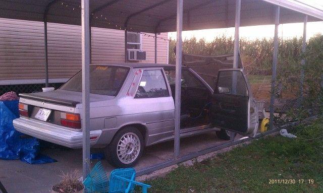 Dusted the car off, pumped up the tyre that had went flat and made sure it still wanted to start (Which it did, thankfully). Assumed the position again with the laptop: 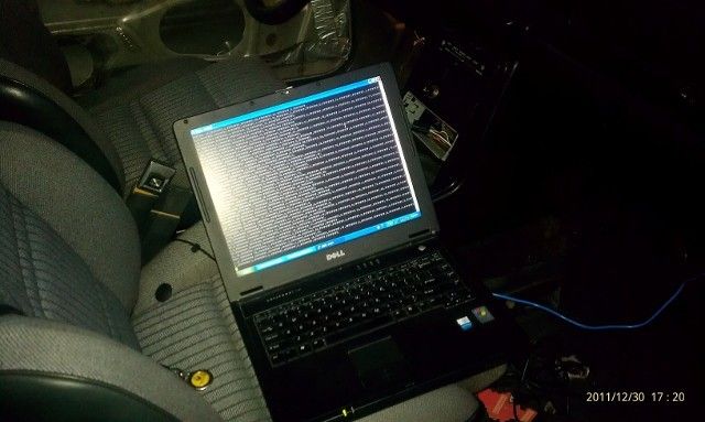 Stuck my nice new shiny program onto the Arduino board and connected it up to the car. 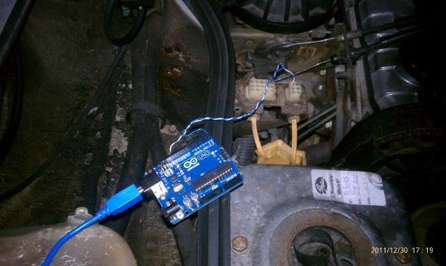 Since the screen is broken (waiting to hear back from the supplier) I have the poutput pointed at the computer screen. Started the car up aaaaaaand... nothing. Nuts. Wrote a different program to see if I was getting anything at all off the car: 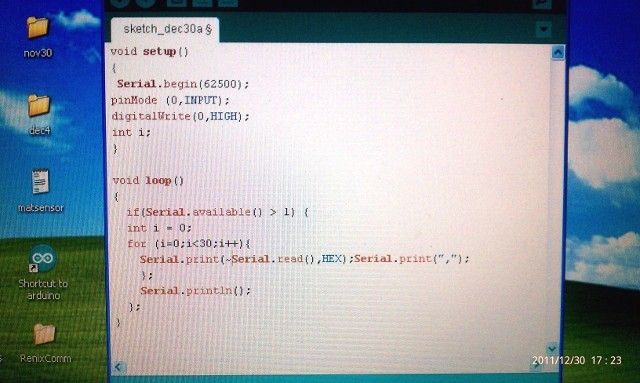 That proved a little better, as it spat out some junk: 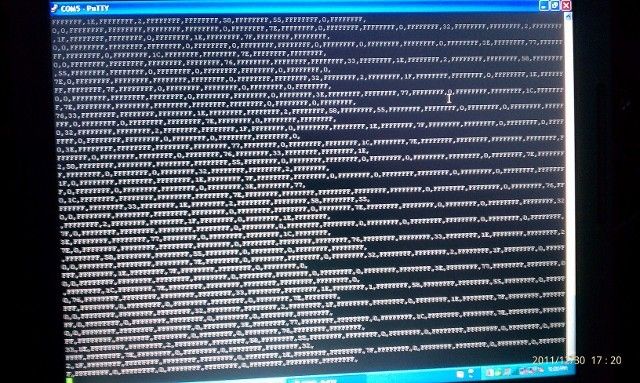 Made a bit of an adjustment to the program and... I have something resembling data: 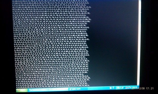 A little more ordered and sensible but there's a lot of random spank in there and it doesn't make a whole lot of sense. I'm attributing this to the fact I'm driving the circuit off the Arduino and it probably just can't sink the current required. I'mma build a better interface to go between it and the car. Wish me luck  --Phil |
| |
|
|
camper damper
Part of things
  Another car bites the dust
Posts: 606
|
|
|
|
|
Love reading your post and love all the code reminds me of my time in collage when I was learning Jave and RPG
|
| |
|
|
|
|
|
|
|
Love reading your post and love all the code reminds me of my time in collage when I was learning Jave and RPG Thanks  I know it's turned into a computers thread, but unfortunately this car has a computer in it... and I'm trying to make sense of it. More the fool me. I didn't know there were that many numbers trapped inside it. I thought they would have all escaped by now, but the more I look, the more there are... ;D The Arduino is nice to work with. the compiler I'm working with uses a variant of C, so learning it has been relatively straightforward. Not that I remember a whole lot of it from University! This is all a bit hit-and-miss as the days are currently quite short (dark here by 6, which is better than there at least, 30.5 degrees North here) but a 7am start lately has meant I finish by 3:30 so there's a little time to do things with the car but not much before the bugs really start to come out. I got bit in about 5 different places. Mosquito welts here come up nearly the size of a 5p piece if you're unlucky. I need to pull my finger out and do the lower balljoints on the front, tighten everything up, stick a few clips back on and I reckon it'll be in fine shape to be able to be moved under its own power. Time will tell. --Phil |
| |
Last Edit: Dec 31, 2011 2:02:07 GMT by PhilA
|
|
|
|
|
|
|
After the removal of a bit of junk from the car with the new little board (which was a long shot anyway, the engine bay I think was a little bit too much for it to cope with) I went to Radio shack and purchased a couple of odds and ends. 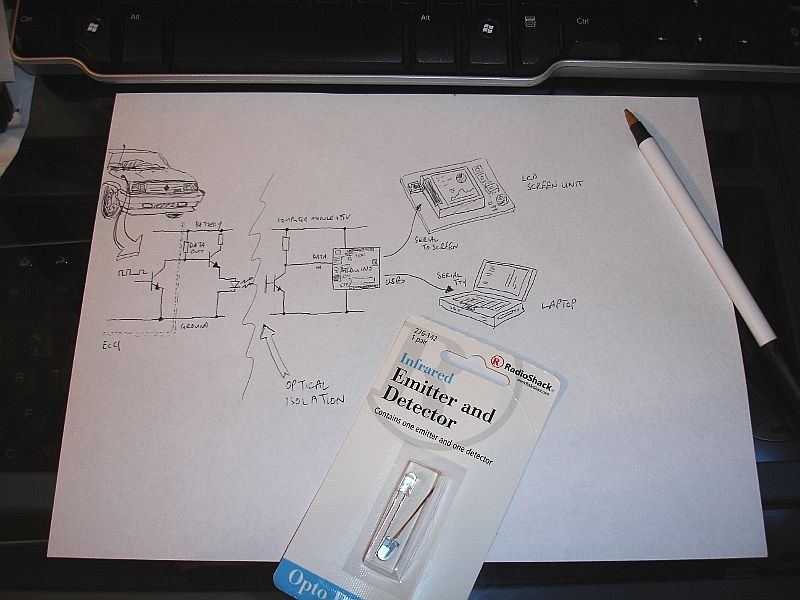 There's the bits in the paper piece there. The blueish one is an Infra-red LED, the same type that's in the remote control for your TV. That's the little V~> symbol on the left of the wiggly line. The clear one is a receiver, similar to the one on the TV set. It is a "phototransistor". Back to the school electronics class, the transistors were the little three legged ones that went up in an interesting puff of smoke when you connect them across a bench power supply. This one only has two legs. The third leg is inside, connected to light-sensitive material. When it "sees" Infra-red light it switches on the transistor. That's the |-K symbol on the right of the wiggly line. I had previously had the Arduino connected directly to the car (blue wire, pictures in previous posting), but that acts too much like an antenna and collects allsorts of unwanted noise. Just stick an AM radio by your car's engine there and start it up. The RF noise the engine makes drowns everything out on the radio. Same thing happens with the miniscule electrical signals I'm trying to collect. The purpose of this is to completely isolate the car from the computer board- the outgoing pulses from the car make the Infra-red LED light up, and the phototransistor sees it and turns the circuit on so the little Arduino board can read it. That's the theory. Need to actually take the bits out and make it work on a breadboard first. Work tomorrow, it's getting late, the coffee is wearing off, so I'm to bed. will pfaff about with it after work tomorrow if I can. --Phil |
| |
Last Edit: Jan 3, 2012 4:10:18 GMT by PhilA
|
|
|
|
|
|
|
Alright, I got a bit further tonight before the wife called me to cook dinner: 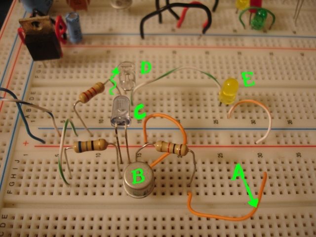 Annotated for your pleasure  Wire A is currently not connected to anything, so transistor B isn't conducting. Infra-Red LED C is off so phototransistor D isn't conducting. For demonstration purposes LED E is off. This is what is meant to happen  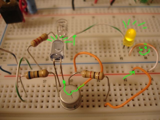 With wire A plugged in to + volts the transistor begins to pass charge and the Infra-Red LED lights up (well, you can't see it because it's Infra-Red so I put shiny green lines), the phototransistor begins to conduct and the yellow LED comes on and there is a smiley face. To prove it works, I grabbed the TV remote and pressed the volume-up button at the sensor. On comes the LED. Win  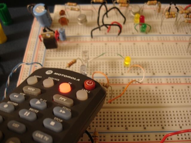 Now just to hook this lot up properly and give it a whirl. A little bit of testing may be required beforehand, which probably won't end up in pictures, haha In this example it only demonstrates I can still assemble a working circuit. The top part of the circuit is connected to the same power rail for demo purposes only. In the working version it will be powered solely from the Arduino.--Phil |
| |
Last Edit: Jan 4, 2012 3:05:58 GMT by PhilA
|
|
Sven
Part of things
 
Posts: 341
|
|
|
|
|
And this is to get a car working, yeh? hahah ...
-Steve
|
| |
1969 Chevrolet 4x4 C10 Pickup
1969 VW extended cab pickup (doka)
1980 Volvo 240DL
1995 Mazda Miata MX-5
2007 Toyota FJ Cruiser
2007 Dodge Ram 2500 Cummins Diesel
2011 MK Indy R (building)
|
|
|
|
|
|
|
And this is to get a car working, yeh? hahah ... -Steve Steve, Not to get it running, no... it is already running really quite well. It just has a few quirks that I just can't get to the bottom of- for instance the open-loop lean running problem, the EGR circuit and a couple other foibles it has. This is to get right down to the fine tuning. The purpose of doing this is to get it so it doesn't stall out at a traffic light when it's cold, or so I can get the mixture just right at light throttle or determine which sensor is causing it to tweak the fuel incorrectly. I need it to be reliable. I would also like it not to destroy the first catalytic converter I put on. Not to soot up the plugs or melt a piston CROWN would be nice as well. Squeezing the last few MPG out of it would be nice too. Plus, it's a pride thing- I was commented at (many, many pages back on this thread) by several members of the Renault owner's group here in the States that no GTA ever runs right any more. Back when I had problems with the injection system leaning out sporadically and it would buck and sneeze down the street- apparently that is the de facto way that Renix operated Alliances run. I decided to heck with that. They ran properly when they were new, the computer in mine is mostly healthy, it is silently sitting there telling nothingness what it is doing but nobody is able to read that because it uses proprietary hardware. I figured if I could overcome that hurdle, build a device that would read what the system is doing on the fly, I can pinpoint exactly what's going wrong and correct it. Saves an awful lot of diagnostic troubleshooting time if you can look at a screen and see that it has flagged that a sensor is out of variance limits. That's something usually that wouldn't be found, at least not until it fails completely... at which point either you're walking home or the damage has been done. This recent excursion into electrical isolation is just because the Arduino board is operating at TTL levels (0v - 5V peak) and the noise on the line is way beyond the threshold it determines as 1 and 0 bits, so it's reading scrambled garbage. If I have the car driven at a higher voltage with a better threshold (IR LED) and the Arduino's data line isolated from the car then it can downconvert locally from the input of the phototransistor and hopefully nix a lot of the noise that's incoming. I hope. Plus, if I get this right, a few people have shown interest in it for their own diagnostics  --Phil |
| |
|
|
|
|
|
|
|
|
It seems that if you figure it out that, you can make various people happy by pinpoint the right bad sensor on the fly...
Always good to know someone to be very foucused on making the best of his car/maker by removing the bad bits...
As always keep up the good work...
|
| |
|
|
|
|
|
|
|
|
Thanks. I'm trying! If I get to the bottom of this I know at least one person who wants one to diagnose why their car runs badly some days and great others.
As a diagnostic tool it will require a bit of knowledge and understanding to use to troubleshoot, as there are two ways the problems can happen (three if you count the combination of the other two): if an input sensor is bad and is giving the computer misinformation, which it calculates upon incorrectly and mis-fuels or incorrectly sets the ignition advance. The other thing is electromechanical, whereby the computer had correctly calculated the fueling but something is wrong (bad injector, poor fuel pressure, jammed actuator etc) and it fails that way. A lot of the time the computer is able to flag this and report back exactly what it sees the problem is. It can continue running in a lot of cases on a considerably poorer manual "Get you home" or "limp" mapping of calculations. I think a lot of the time these cars are running in limp mode and people just don't realize...
|
| |
|
|
Sven
Part of things
 
Posts: 341
|
|
|
|
And this is to get a car working, yeh? hahah ... -Steve Not to get it running, no... it is already running really quite well. It just has a few quirks that I just can't get to the bottom of- for instance the open-loop lean running problem, the EGR circuit and a couple other foibles it has. I understand completely, I can be a bit of a bulldog myself! That was my first attempt at a bad joke of 2012! I admire your effort and skills! -Steve |
| |
Last Edit: Jan 4, 2012 21:53:25 GMT by Sven
1969 Chevrolet 4x4 C10 Pickup
1969 VW extended cab pickup (doka)
1980 Volvo 240DL
1995 Mazda Miata MX-5
2007 Toyota FJ Cruiser
2007 Dodge Ram 2500 Cummins Diesel
2011 MK Indy R (building)
|
|
|
|
|
|
|
Not to get it running, no... it is already running really quite well. It just has a few quirks that I just can't get to the bottom of- for instance the open-loop lean running problem, the EGR circuit and a couple other foibles it has. I understand completely, I can be a bit of a bulldog myself! That was my first attempt at a bad joke of 2012! I admire your effort and skills! -Steve haha Won't be my first missed joke of 2012  I could have picked a simpler project vehicle, it's true. This one, however, has opened up a bunch of interesting learning avenues. It has also gotten me back into hacking about with electronics, which I have always loved but never had much of a chance to do anything with. Sadly, looking at it, that little board I bought is powerful enough to replace the car's fuel injection system and then some. With a few extra bits and bobs I could get it to run the engine lol --Phil |
| |
Last Edit: Jan 4, 2012 23:09:39 GMT by PhilA
|
|
|
|
|
|
|
|
I just wish I understood more of what I was reading, electronics and computers are like a foreign language to me and while I understand the odd bit here and there, the stuff you're doing is both fascinating and daunting and makes me glad I don't have a car with a magic box under the bonnet.
|
| |
|
|
|
|
|
|
|
I just wish I understood more of what I was reading, electronics and computers are like a foreign language to me and while I understand the odd bit here and there, the stuff you're doing is both fascinating and daunting and makes me glad I don't have a car with a magic box under the bonnet. In some ways it's good, other ways it is not. I'm having to bounce back quite hard into programming for a small-memory slowish-processor device (Not that 16MHz is by any means slow, but sharing interrupts and communications channels etc... funfun. Either way life would be a lot easier if the car was a few years younger, as somebody else has already done this hard work and the standards are quite a lot more open. OBD-II. However, good news is to be had. Version 0.3.7 of my software finally came to life properly last night, producing sensible numbers when fed with data pushed from the serial port on my computer, pretending to be the car. If I have time I'm going to try and hook it up tonight and see if I get any numbers on the screen. I hope I do. If I get some boring looking numbers I'll be happy! --Phil |
| |
|
|
|
|
|
|
|
|
Today's task was proving that in a laboratory environment something will work fine; stick it into the real world and it will fail totally.
I swear this dratted car is conspiring against me.
More soon.
|
| |
|
|
|
|
|
|
|
It is official. I am a complete tool.  Have an arty picture to detract from the fact there's no pictures of anything to do with a car on this half of the page. 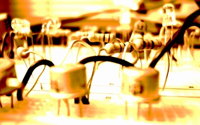 Getting lost in a small city of electronic components, my mind has gone awash. Otherwise known as plank here forgot that he needed to electrically invert the signal off the car... a fact I determined many months ago. The board itself: 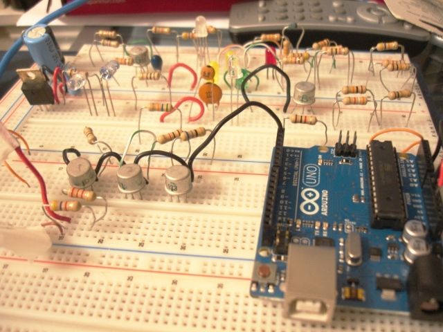 Threw a quick NOT NOT NOT together (foreground, the three little metal transistors), which as we all know it ain't not what you ain't not looking' at. I threw the pre-recorded data into the NOT (first one), read it off... and it came out fine. Took it off the second (NOT NOT) which came out scrambled but still kinda recognizable- very similar to what I got off the car tonight- and then again as proof of the pudding, making it NOT again made it NOT of a NOT of a NOT which was, uh... correct! Lost you? Yeah, I lost myself there for a while too. What this means? If I stick a transistor in there somewhere I might actually get it to work. --Phil Edited for speelink and grammer what I'm not good at no. |
| |
Last Edit: Jan 10, 2012 3:23:57 GMT by PhilA
|
|


