|
|
|
Apr 26, 2013 17:12:13 GMT
|
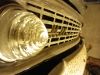
Hi guys! My name is Nick. I've been into hot rods and custom cars since I was a kid. For over 13 years, I've been learning the art of metal shaping starting out with a set of about 9 hammers, some dollies, and a 3/4" rubber mat and things have kinda evolved from there. I'd like to extend my hand in appreciation to all the members who have the same passion for cool cars and enjoy taking the time to share their knowledge and experiences. I was hoping to share a completed project built entirely from scratch out of steel that both my dad and I are quite passionate about. This got me hooked on fabricating.  To create this sports car some styling cues were borrowed from classic European sports cars as well as American muscle cars of the late 60's and the SR-71 Blackbird played a key role with regards to the overall shape of the vehicle - such as the concave surfaces flowing from the front fenders and into the turbos... The look we were after with the fit and finish once complete was as if it rolled off a 60's factory production line.   Upper turbo scoops used for the cold air induction...the 365HP SBC350 engine loves all that extra air. The front of the engine(pulley end) is facing the rear of the vehicle...for better weight distribution towards the center of the car. Thanks for looking.  |
| |
|
|
|
|
|
|
|
Apr 26, 2013 17:26:08 GMT
|
|
You hammered that out of sheet steel? WOW!! That's simply incredible.
Can't wait to see more but for now I just have to say, you haz skillz!! Welcome to Retro Rides.
|
| |
|
|
|
|
|
Apr 27, 2013 16:11:00 GMT
|
|
cor blimey! thats a lot of work gone into that.would love to see some build up pics of it.
|
| |
too many toys..too little time...and usually too little money.
|
|
|
|
|
Apr 27, 2013 17:32:33 GMT
|
|
I can't say the styling is my bag, but wow! That's impressive work. The more I look at it, the more the craftsmanship becomes evident. Smooth reflections; tight, parallel shutlines. Skills!
|
| |
|
|
|
|
|
Apr 28, 2013 12:38:21 GMT
|
Thanks for the great welcome Gents and I really appreciate the kind words. For those not familiar with the SR-71 Blackbird, here's a photo.  The build took us 8000hours over 8 years to complete. So yeah, it was a ton of work, but it was passionate work. This was basically my apprenticeship in metal shaping, chassis fabrication, body work, paint, and upholstery. Forgot to post a picture of the finished interior the other day...  Loosely based around a cockpit it's got all brushed stainless trim and VDO gauges. Well here goes the actual build. By no means does it cover every aspect of the journey, it'll give you some idea. Some people on this site may be able to pull off some or all of this fabrication work in their sleep, I learned as I went. Anyway, enough blah blah blah... hope you enjoy. |
| |
Last Edit: Apr 15, 2015 15:27:29 GMT by invision
|
|
|
|
|
Apr 28, 2013 12:41:33 GMT
|
I can't say the styling is my bag, but wow! That's impressive work. The more I look at it, the more the craftsmanship becomes evident. Smooth reflections; tight, parallel shutlines. Skills! Thanks Darryl and I appreciate your honesty...no worries. There are certain design elements that I would have liked to change as the end of the build was approaching ... but it's a project that I wanted to see through to the end. We set a 60's sports car theme for the build...and along the way there were some changes to the styling from the initial concept...but if one keeps making changes...the project would never get finished. Rhythm was completed in 2008 and licensed as a fully functional road vehicle. After taking almost a year off...I decided to start "the next one". While I am quite pleased with the way Rhythm turned out...I wanted to make some changes to the styling. And the most effective way of modifying the body would be to hand craft another one. Simply called R2...this is a fresh sheet of paper design, LS6 powered, 500+HP mid-engine sports car metal crafted again from flat sheet metal and loosely resembles Rhythm. However, the major difference comes in the overall tightness of the proportions resulting in a very modern appearance. Rolling on 275/35/R18s in the front & 315/30/R19s rear R2 is 28” shorter, 6” narrower, and a little over 900lbs lighter. I invite you to check out the build progress on my facebook site: www.facebook.com/iNVisionPrototypesThe body panels have all been shaped and now it's time to weld them all together. Thanks again, Nick |
| |
|
|
|
|
|
Apr 28, 2013 13:47:23 GMT
|
|
What an amzing build. Looks like some sort of 1960's concept car! Am now going to scuttle off to facebook to look at R2.
Matt
|
| |
|
|
|
|
|
Apr 28, 2013 14:01:25 GMT
|
|
The sheet metal work on this is incredible!
The styling looks like a 50's idea of a car from the future!
How much does it weigh?
|
| |
Last Edit: Apr 28, 2013 14:09:59 GMT by wheeler
|
|
|
|
|
Apr 28, 2013 20:12:18 GMT
|
|
Impressive!
And this thread needs more pics.
I like R2 too, any sketches of dreamed end result?
|
| |
 Click picture for more |
|
|
|
|
Apr 29, 2013 11:59:28 GMT
|
Thanks guys!! The car comes in just over 3400lbs(1542kg). |
| |
|
|
|
|
|
|
|
Apr 29, 2013 12:03:21 GMT
|
The car ran with the he transverse V6 until the SBC 350 was ready, then it was deep 6'd. This little change made putting your foot into it a little more fun...at the expense of a much smaller trunk. To maintain Rhythm's theme I picked up a hot rodded Chevy 350 and mated her to a Caddy Seville TH325-4L trans(4spd). The added weight and shift in weight bias within the car was a large concern. So with specific component upgrades, mounting the engine in a reverse rotation manner (pulleys facing the rear) and pushing the engine to the front as far as possible without compromising the CV angles we were able to fit the powerplant in quite nicely. With any project, as I'm sure many know there is always a tweak here and there. In this case, there were 4 major tweaks...first, we had to create a BOP plate to connect the trans to the engine...which wasn't too bad. Second, with the unit sitting backwards, we ended up with 3 reverse gears and one forward gear! Wild huh? So, that meant flipping the differential 180* though the use of another adapter plate. The other added benefit was that it lowered the unit by 1.375"...lower centre of mass is always an added benefit. In doing that though, the stub shaft had to pass though between the crankshaft journals. Even wilder huh? This lead up the the 3rd tweak whereas a hole was made in the oil pan, sleeved, and therefore allowed the shaft to pass through. When the oil pan is installed there, the sleeve has 3/16" clearance between it and the journals that move past it. Correct spacing was accomplished by carefully measuring the distance from the rear of the engine block to where the centre of the stub shaft was to be. Then the adapter plate with specific thicknesses were created to get the spacing just right... and finally 4th, the design and fabrication of a set of reversed headers. Here are some of the initial pictures of the mock up.  After the rear BOP plate was created ... I needed a set of heads.  As mentioned above, adapter plate thicknesses played a crucial role in centering the drive axle between the crank journals...definitely followed the "measure 3 times...cut once" rule here.  All together and bolted. Unfortunately not a runner yet...  Some math to get the centre of mass correct...  In about an hour everything was stripped out and clearanced for the new engine.  Trimming out the old mounts...  You see what I meant about the stub shaft...going right though the oil pan...directly between the crank journals.  That Edlebrock air breather was changed out for the cold air induction unit I fabricated. |
| |
Last Edit: Apr 15, 2015 15:28:09 GMT by invision
|
|
Kev
Part of things

Posts: 221
|
|
Apr 29, 2013 12:35:25 GMT
|
|
How the... This is absolutely insane! Welcome!
|
| |
|
|
|
|
|
Apr 29, 2013 17:11:55 GMT
|
|
Very welcome, awesome work has happened here, jaw dropping.
Had dreamed the idea of a complete build... but I don't have the patience.
|
| |
|
|
retrobastard
Part of things
Tits or tyres means trouble
Posts: 394
|
|
Apr 29, 2013 17:36:40 GMT
|
Cracking work my friend! Is your dad Chip Foose?  ? Or Troy Trapanier? |
| |
|
|
|
|
|
Apr 29, 2013 20:25:54 GMT
|
Nice to see you on hear Nick, Hurry up and start posting up the current project |
| |
|
|
|
|
|
Apr 30, 2013 12:21:43 GMT
|
Thanks again everyone! I've been looking around at your rides as well. There is a lot of great talent and some really sweet rides here on Retro Rides. Lovin' it! ;D Nice to see you on hear Nick, Hurry up and start posting up the current project Hey claymore! Great to see you on here as well. Small world! I'll be starting a thread for R2's build just as soon as I get this one done. Each time I plan to start the R2 thread I get looking at other peoples' rides and projects. I really enjoy watching what others are doing. |
| |
|
|
|
|
|
Apr 30, 2013 12:24:55 GMT
|
Here's a little metal shaping...  Did a little tuck shrinking to create the housing's shape.  Shaping and scribing the duct attachments. After welding it up, it's mocked up in the vehicle...now its time for some primer and paint. When the top turbo fans are switched on, the engine loves it... all that extra cool air. Thanks for looking! More to come... |
| |
|
|
|
|
|
|
|
Ok...here goes the exterior sheet metal segment of Rhythm's build. As a precursor to the pictures, the only tools I started with to shape the steel panels was a set of about 9 hammers(you'll see them hung up in some of the photos), some dollies...creating more as were required, and a 3/4" rubber mat. Unfortunately at the time, I was unaware of Lancaster shrinker/stretchers, English Wheels and planishing hammers...they would have made life soooo much easier.  The turbos were created by first rolling the sheet metal over a large PVC pipe...then planishing the material with a hammer and dolly to stretch it and give it the convex curve. To smooth out the highs and lows, the turbo was sanded with a long board to illuminate the highs ... followed by more hammer and dolly work.  This was created using a very primitive english wheel that I built using two truck bearings shown below...  In an effort to speed up the process I was wondering if two steel wheels, one with a CROWN...the other flat, would produce the same result as me stretching the metal by hitting the hammer against the dollie in a longitudinal direction. After scrounging some bearings, box tubing, and utilizing the adjuster on our press I came up with this crazy machine. And while there were some serious drawbacks like the height between the anvil mount arms, and the extremely narrow point of contact ...it worked! Yes, there was some tracking in the pieces...but most of them were smooth out running perpendicular with really light pressure...and the remainder with the good ol' hammer and dollie.     Yes, that was a Jag bonnet, that was cut up and 'readjusted' for a more aggressive appearance. Thanks for looking... there's more to come. |
| |
|
|
rems
Part of things
Posts: 150
|
|
|
|
this is absolutely stunning |
| |
|
|
|
|
|
|
|
|
I just want to clarify I wasn't trying to be negative, but I hope/think you got that I was being positive about the quality of the work.
No way could I ever produce those lines, over an entire body, in GRP, which is a material possibly more suited to those shapes.
I think you passed your apprenticeship with flying colours. Orz
|
| |
|
|
|
|


 [*]
[*] [*]
[*]


 ? Or Troy Trapanier?
