|
|
|
|
|
I've gotten to that stage again, where I've ran out of things to do to keep my hands busy (turns out being a draftsman is a damned boring job) so after a few madcap ideas, I'm going to turn one of my old spare turbos into a small jet engine. The plan isn't to have a fully refined item, but rather something that just kinda works, and makes lots of noise  So having the utmost efficient design isn't a high priority. The turbo I'll be using, is a GT1549, from an old Rover 2L diesel. There's two of these sitting in my basement, and both have gone crusty from being sat in the damp garage, so no worries if they explode 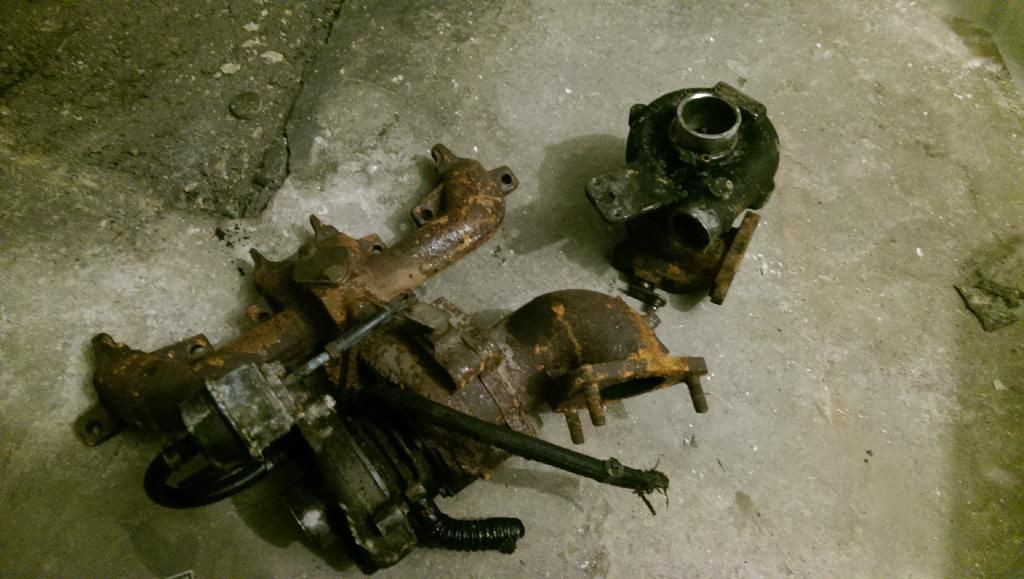  The AR of the turbine housing is pretty small considering (as can be seen by my thumb nearly filling the turbine inlet!) so should mean it at least won't require a combustion chamber the size of a small county, with a fuel requirement to equal. A small butane blowlamp will be the fuel source and regulator. 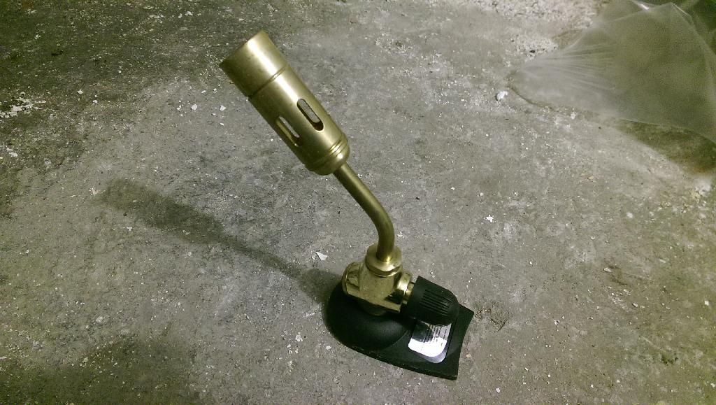 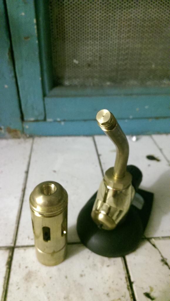 As I've got a bigger version, this one is surplus to requirements. I'm assuming the tiny restrictor in the end wouldn't flow anywhere near enough fuel to have it self-sustain, but if that proves to be right, there should be differing sizes available  Nice and easy to fit with it being essentially a bolt too! The part that's always put me off before, is the combustion chamber.... But as I work at a waterjet and laser cutting company, the sheet metal work and flanges are no longer an issue  There seems to have been some innovation in the past few years too, as the only flame tubes that seemed to work, were along this design: 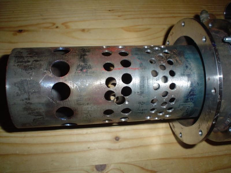 Which... is very prone to being a git to get right However, I've seen a few using simple perforated exahaust tube, like this: 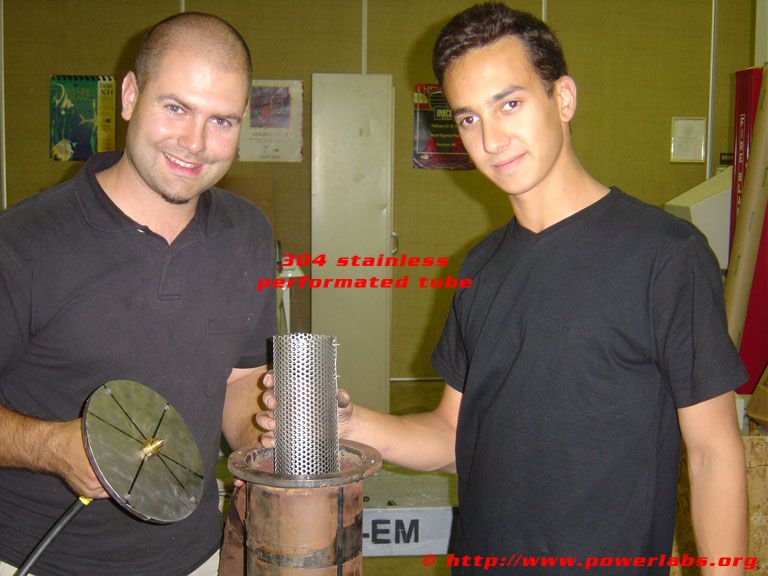 Which will make things much easier Next on the agenda - oil supply. Again, previous designs have all either been engine oil pumps, driven by a bodged fitting to an electric motor, or custom-made pumps (usually made from a molested engine oil pump!). But now I know turbos don't actually need "pressure", but actually just need flow, I've seen another method to draw from: using a power steering pump 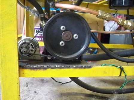 Which again, I can improve and go one step further - by simply using an electric power steering pump, such as is fitted to many vauxhalls:  These go for as little as £10, so a perfect solution for a cheap project Ignition hasn't been decided, but may make use of something I threw together a few years ago: To make it easier to operate in the middle of a field, it'll possibly use a 500w invertor to create the 240v required, so it can use the same 12v source the oil pump will use Once I'm back at work, I'll make a start on drawing up the flanges required |
| |
Last Edit: May 18, 2014 17:51:44 GMT by chairchild

You're like a crazy backyard genius! |
|
|
|
toreno
Part of things

Posts: 385
|
|
|
|
|
i started to make one of these turbo jet engines some years ago never finished it though cant wait to see your work
|
| |
|
|
|
|
|
|
|
When I used to attend the model engineering sessions at Leek, Staffs, college a chap there build a gas turbine engine from scratch. It was intended for use on a lawnmower ! He made the parts out of foam and then had Taylormade Castings of Stoke-on-Trent cast them in alloy. Once assembled he had it running in the workshop on propane. It ran quite well until the heat damaged the edge of the turbine vanes and housing. This was part of his design planning as he wanted alloy so he could then see where the problems arose and could redesign to avoid them before having he final product cast in a more expensive material. Unfortunately I left Leek and started at Burslem college so don't know the final result but the idea of a gas turbine lawnmower sound brilliant Paul H |
| |
|
|
|
|
|
|
|
gas turbine lawnmower sounds like something that would get me cutting the lawn with a smile! Been looking at a few basic calcs for the combustion chamber which are: Flame tube diameter = 2x compressor inducer diameter Flame tube length = 6x compressor inducer diameter Combustion chamber diameter = 1" extra on the radius Which with a compressor inducer diameter of 34.7mm, gives me: Inducer: 34.7mm flame tube diameter: 70mm flame tube length: 208mm Housing diameter: 120mm ~4.75" But for ease, the flame tube I've bought (for £2.75) is 38mm x 250mm, and I'll use either a 4" or 5" tube diameter for the housing. All nice and easy so far |
| |
You're like a crazy backyard genius!
|
|
sparkyt
Posted a lot
selling stuff
Posts: 1,767
|
|
|
|
|
Bud when you cut your flange for your gt turbo the 3 bolt triangular one would you cut 2 I need one for my beetle project .
|
| |
|
|
|
|
|
|
|
there's a good chance it'll be nothing like the one needed for your vw I'm afraid - this flange pattern seems to be used pretty exclusively by the L series it seems? Would genuinely love to be proven wrong however (more potential upgrades for Rovers!) Throw up a pic of yours, and I'll see what I can do |
| |
You're like a crazy backyard genius!
|
|
|
|
|
Mar 10, 2014 17:39:58 GMT
|
Little bit of work done today - got the general layout of components sorted  The base will bolt onto an old spare wheel for stability, and the whole unit will be supported via the turbine housing bolts (which normally has a downpipe fitted to it!) and the combustion chamber will sit vertically The oil pump will sit inside the frame, making it relatively stable for use on the common land behind the house (no way in hell am I starting this indoors!  ) |
| |
Last Edit: Mar 10, 2014 17:42:28 GMT by chairchild
You're like a crazy backyard genius!
|
|
MrSpeedy
East Midlands
www.vintagediesels.co.uk
Posts: 4,786 
|
|
Mar 10, 2014 22:23:14 GMT
|
|
Did you see the episode of "Scrap Heap Challenge" when they built jet powered GoKarts and raced them at Santa-Pod? One team built a pulse jet and the others 'converted' a turbo.
On a side note, how did you build that ignitor? That would be perfect for firing my Spud Cannon! (I call it a cannon for a reason ;)lol )
|
| |
|
|
|
|
|
|
|
it's amazingly simple: Light dimmer switch (set to about 1/4, max) capacitor from a microwave Ignition coil (mine's from a motorbike - wasted spark setup for ease) Wire up in series, plug into the mains Estimated 60kv+ from the length of the sparks |
| |
You're like a crazy backyard genius!
|
|
sparkyt
Posted a lot
selling stuff
Posts: 1,767
|
|
|
|
|
It's ok now bud I found a 34mm drill bit .. my flange is done
|
| |
|
|
|
|
Rich
Club Retro Rides Member
Posts: 6,256
Club RR Member Number: 160
|
Small jet engineRich
@foxmcintyre
Club Retro Rides Member 160
|
|
|
It's ok now bud I found a 34mm drill bit .. my flange is done  |
| |
|
|
|
|
|
|
|
well... could get that hole tapped for ya 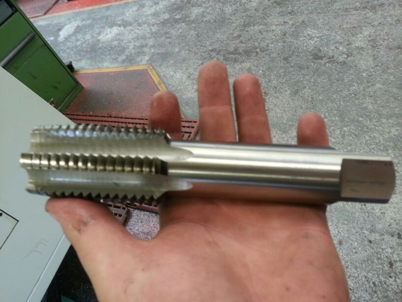 |
| |
You're like a crazy backyard genius!
|
|
|
|
|
Mar 12, 2014 20:55:24 GMT
|
found a bit of 4" pipe lying around at work, was the perfect length I was after too! (300mm) 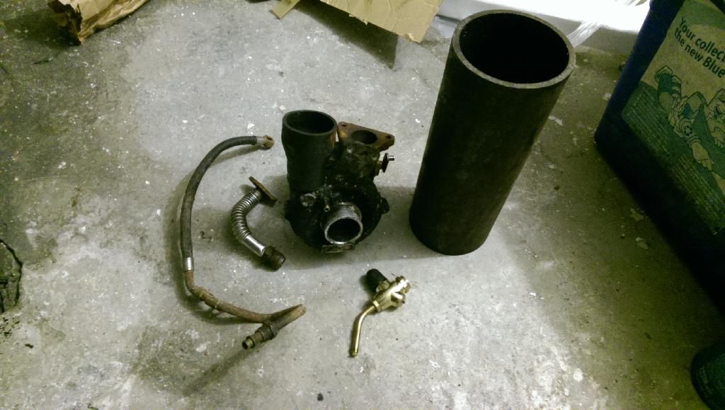 Dug out an oil feed and drain for the turbo too, and removed the plastic shroud from the blowlamp. Not like it serves any purpose in this guise anyway... Combustion chamber flat sections can now be drawn, and cut. Going to have the main tube removable, using 6 m8 bolts each end, and no doubt a copious amount of instant gunge to seal up |
| |
You're like a crazy backyard genius!
|
|
|
|
|
Mar 14, 2014 19:32:52 GMT
|
A couple more parts collected today! 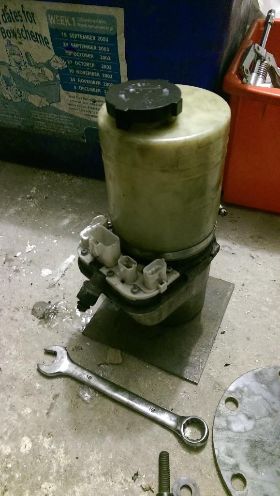 An electric power steering pump, of Vauxhall origin - two big beefy power wires, but two extra plugs with many pins... if I can't find any wiring information online, I'll just take the thing apart, and hardwire it But a "low" and "high" feed rate would be nice to aid with warmup 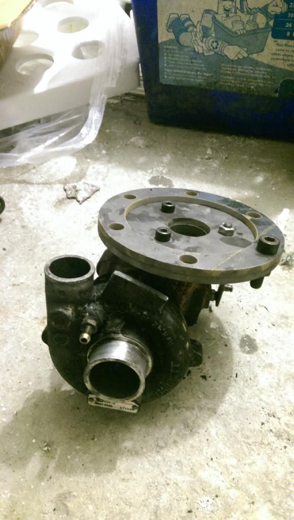 Turbo spacers, baseplate, and one of the flanges bolted together - I made a cockup however, and when drawing the flanges, I put the 15mm head diameter of the m8 bolts I was going to use.... I forgot to change them to 8mm holes before cutting. So m10 bolts with large washers will be the order of the day here! 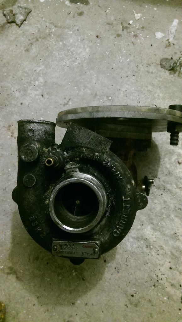 Also spent a couple of minutes cutting off the actuator mount, as it was in the way, and clocking the turbo so the oil drain will be in the correct orientation 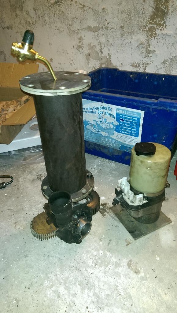 And a dry-run for general sizing, of where the combustion chamber should sit. Picking up the support frame tomorrow, so the pump will sit below the turbo. At that point, the oil plumbing can be figured out, as well as mounting the pump in a neat + tidy manner |
| |
You're like a crazy backyard genius!
|
|
|
|
|
Mar 15, 2014 13:19:24 GMT
|
Picked up the framework today... and realised I'd made another boo-boo 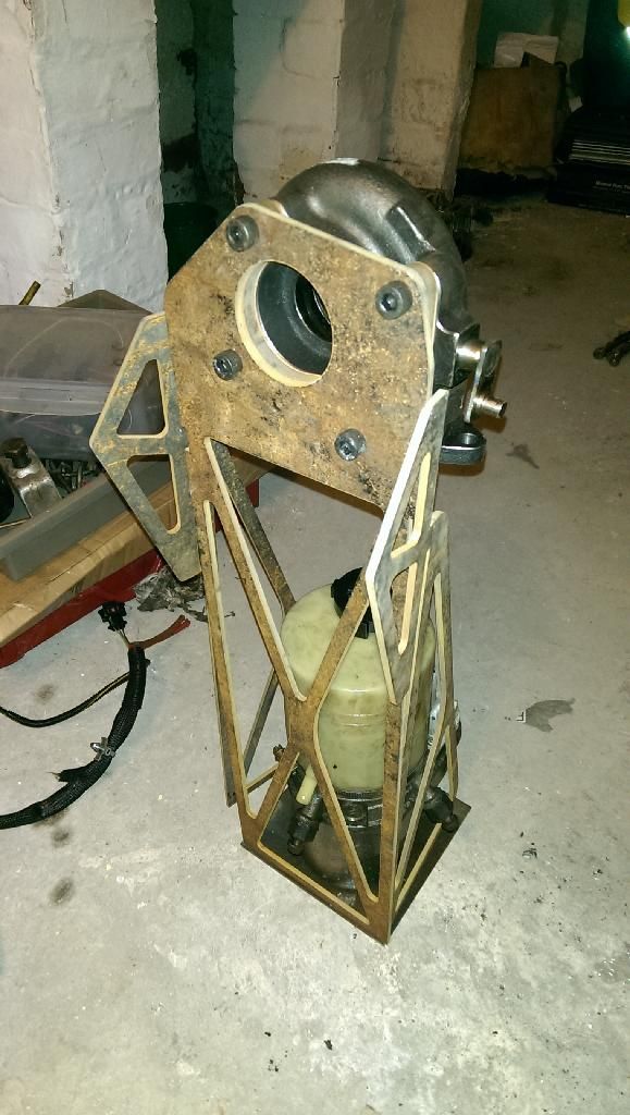 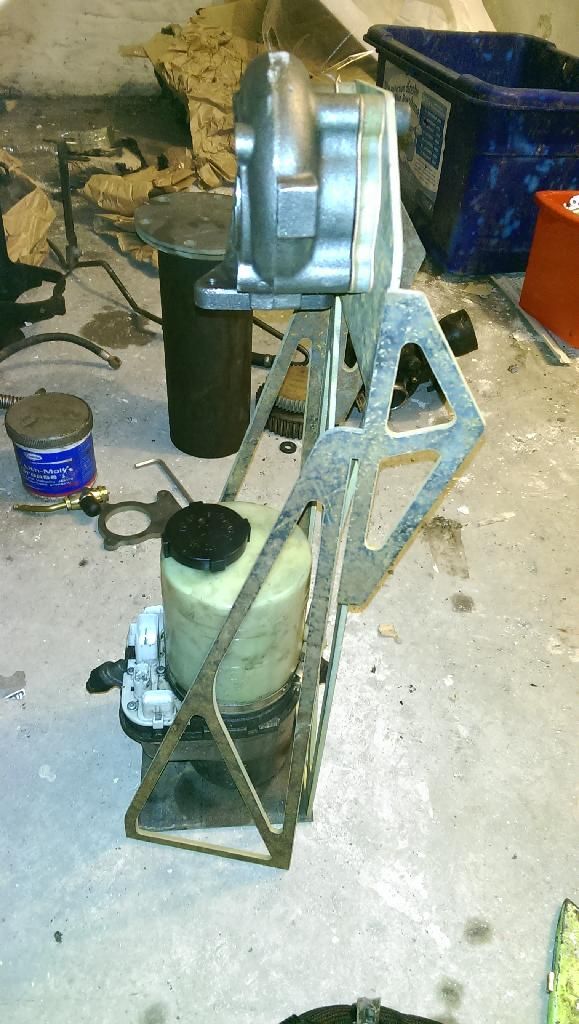  I've put the bolt pattern on upside down  But as can be seen, the power steering pump is bigger than anticipated too, and it would end up looking pretty messy by the time it's plumbed in - and what with the turbo being mostly hidden, it would take the attention away from what little action the jet would be making. So another redesign is in order. If I put the combustion chamber under the turbo, it would make getting to the fuel and ignition points a PITA. So, it's going to go out at 90 degrees, with the pump still straight under the turbo. The space this leaves, can then be taken up by the battery required to run the electronics. Laid out on the floor, it would kinda look like this:  The battery and the pump would be the ballast, and the turbo would be fully supported by the combustion chamber - no big brackets covering it up Now I need to sort out the frame to hold the chamber, which will be attached by stainless steel (to try to slow the transfer of heat to the rest of the stand) May well make the side supports from aluminium, to dissipate the heat that does transfer through. The original pump housing will possibly be used, just trimmed down and bolted to the new baseplate |
| |
You're like a crazy backyard genius!
|
|
|
|
|
Mar 15, 2014 17:00:58 GMT
|
Another setback - wired up the pump, and toyed with the 3 wires I was supplied (according to instructions, these are all that are needed!) Nothing happened whatsoever  So it had to come apart. Took a fair bit of fiddling, gouging, levering, and wanting to burn the damned thing to the ground - but I got it apart! 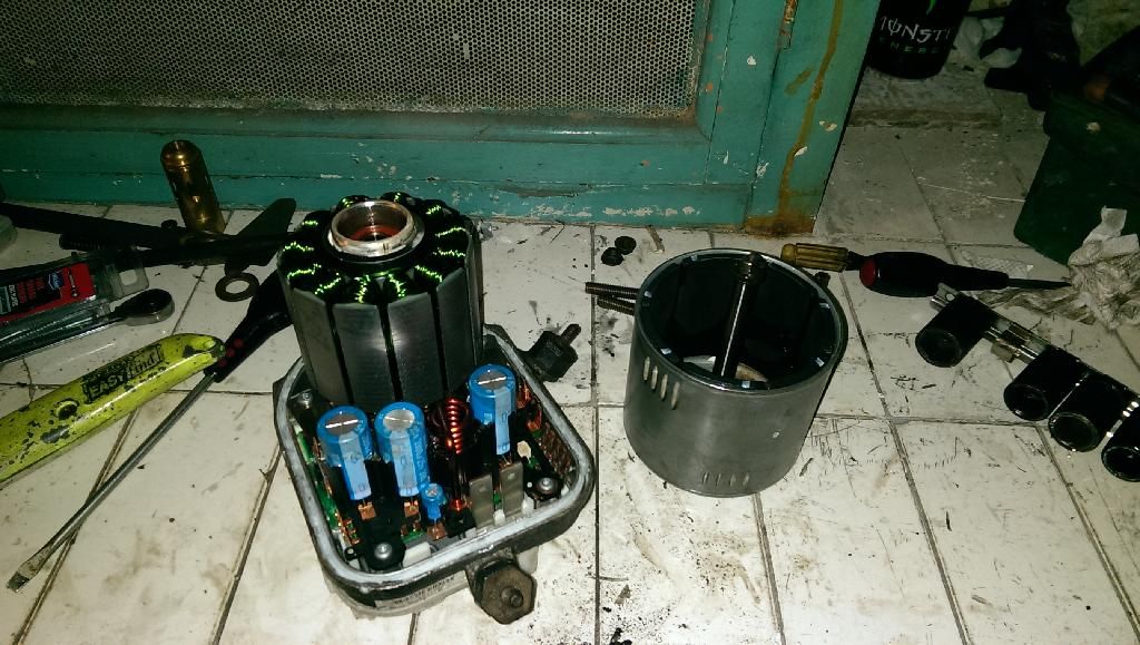 After removing the core+board, it's a full on electronically switched core - no chance of just flicking 12v to a couple of bits. Looks like the plug that wasn't supplied, is the one that supplies engine speed/road speed/etc. So unless I can come up with something to directly drive it, this is dead in the water. Surprisingly, the two gears that actually do the pumping, are TINY! 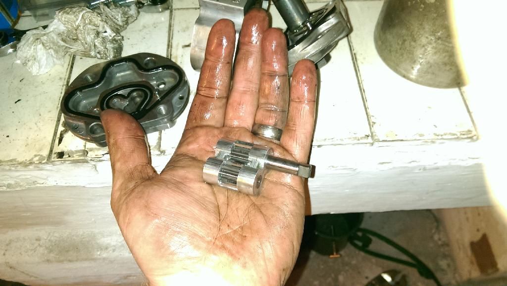 |
| |
You're like a crazy backyard genius!
|
|
Rich
Club Retro Rides Member
Posts: 6,256
Club RR Member Number: 160
|
Small jet engineRich
@foxmcintyre
Club Retro Rides Member 160
|
Mar 15, 2014 19:02:56 GMT
|
|
Citroen saxos and early electric pump Reno clios have a simple 2 wire pump setup if it's any help.
|
| |
|
|
|
|
|
Mar 15, 2014 20:36:48 GMT
|
it certainly is! I actually delved a bit deeper into the circuitry, and was seriously contemplating replacing the whole logic board with a brushless motor controller for an RC car. But it appears to have FOUR switched poles, rather than the usual 3. Now bidding on one on ebay Shame I've pretty much wasted £25 on this other one |
| |
You're like a crazy backyard genius!
|
|
toreno
Part of things
Posts: 385
|
|
Mar 16, 2014 10:27:14 GMT
|
found the remains of mine so your doing better than me already 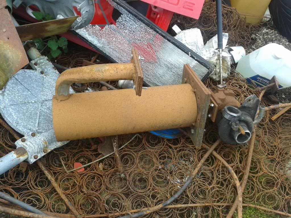 |
| |
|
|
|
|
|
Mar 16, 2014 20:01:19 GMT
|
ooh, what turbo was your using? And did you have any of the other parts planned, or was that literally as far as you got? Dug out the Rover turbo outlet pipe and had a play with it for a few minutes - looks to be 100% utterly perfect for how I wanted it to be!  Nice gentle swooping bends, will come into the chamber at a tangent, and upwards at a slight angle (it'll become more obvious once I start throwing the core together). Missed the post office yesterday, so didn't get to pick up the exhaust pipe. Dammit, lol |
| |
You're like a crazy backyard genius!
|
|
|
|


 So having the utmost efficient design isn't a high priority.


 Nice and easy to fit with it being essentially a bolt too!
 There seems to have been some innovation in the past few years too, as the only flame tubes that seemed to work, were along this design:


 )
)


 So it had to come apart.

