|
|
|
May 20, 2018 11:35:26 GMT
|
Still no sprockets, so I thought I'd continue with the rear light.. Starting with this not quite flat steel sheet. By not quite flat I mean the sheet has had a big cross pattern pressed into it which I though would be good for the back of the light box.. 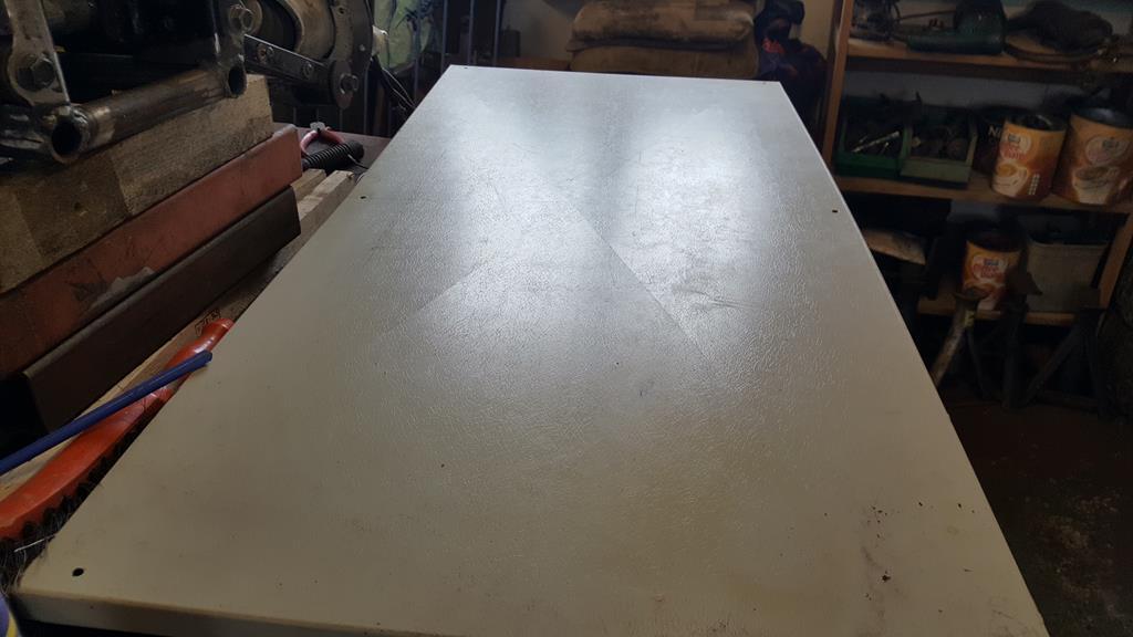 Marked out ready for cutting. 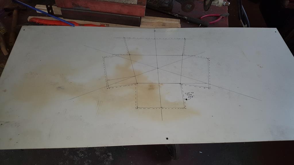 Lot's of chopping, welding and weld dressing later I had this. 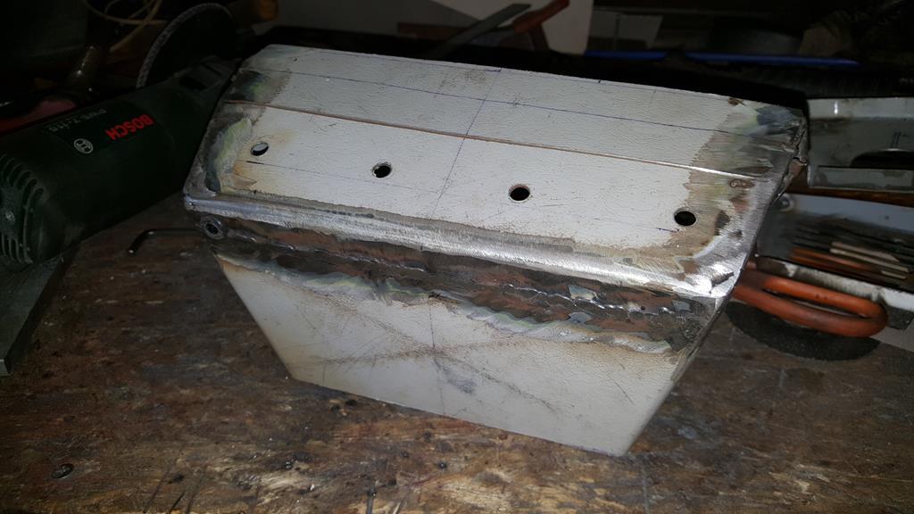 The cut out at the base is so the box can fit over the anit roll bar tube. 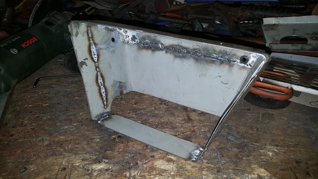 These are the bulb holders I will be using.. 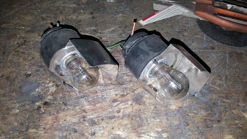 This ally plate is the right thickness to hold the er.. holders nice and tight, so five holes and a bit of cleaning up later. 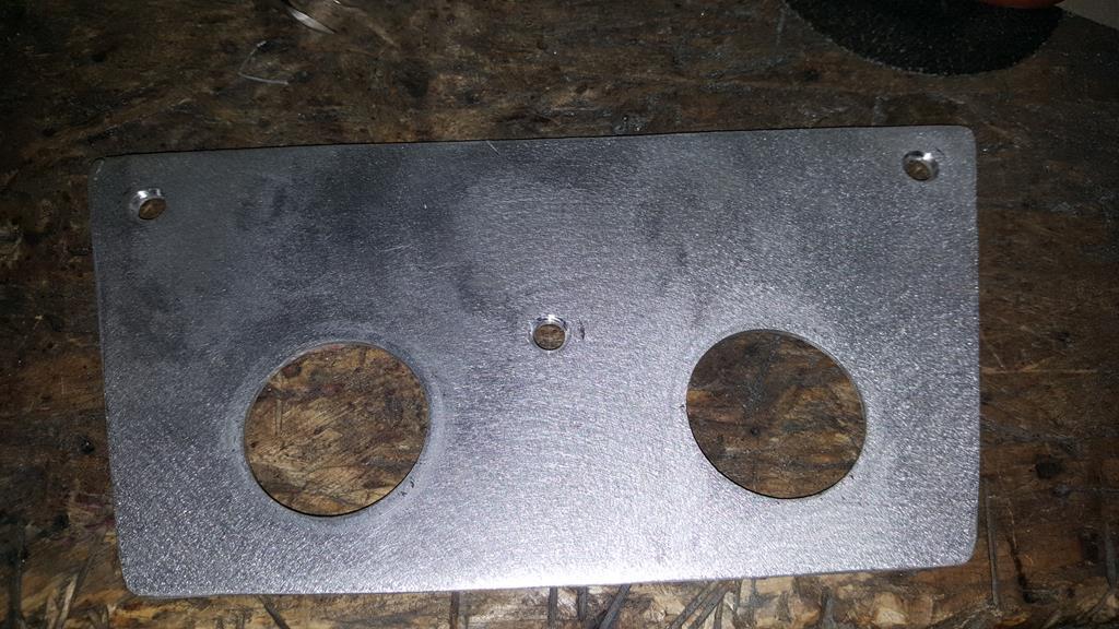 To mount the bulb holder plate to the inside of the light box but leave enough space behind for wiring etc I made one of these.. 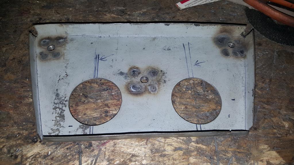 Captive nuts welded on the back. 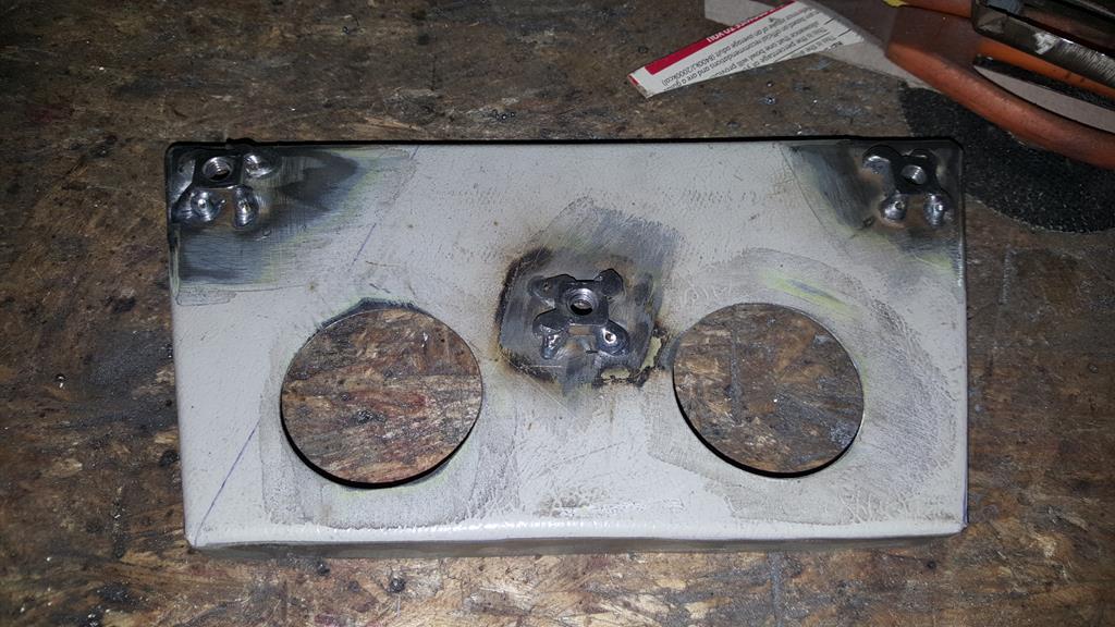 A quick bulb test fit. 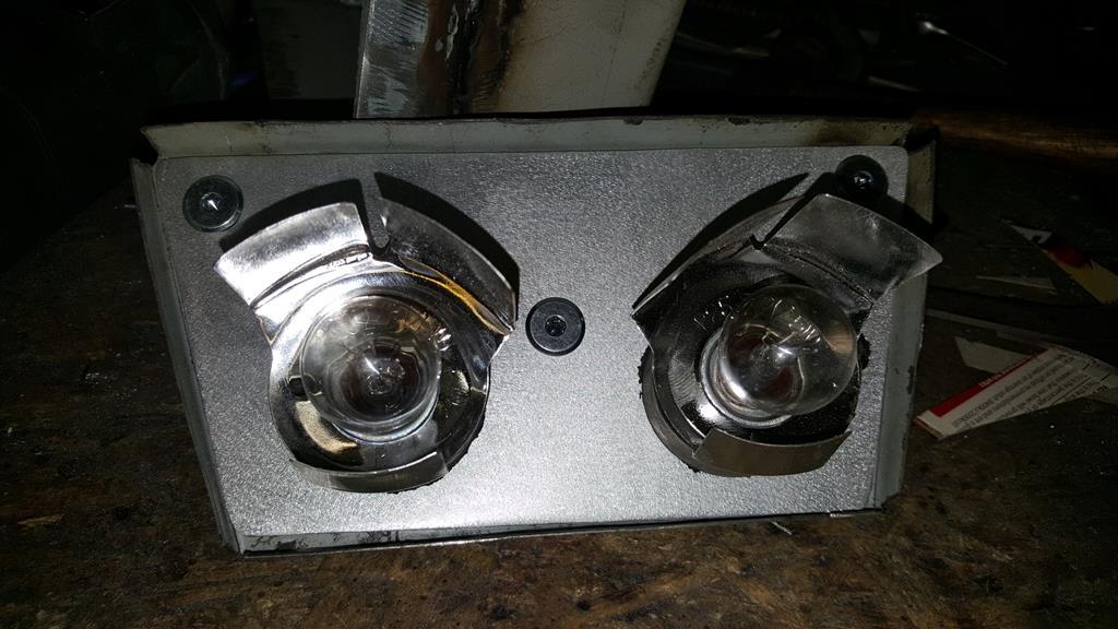 Curved panel made to fit the anti roll bar hole.. 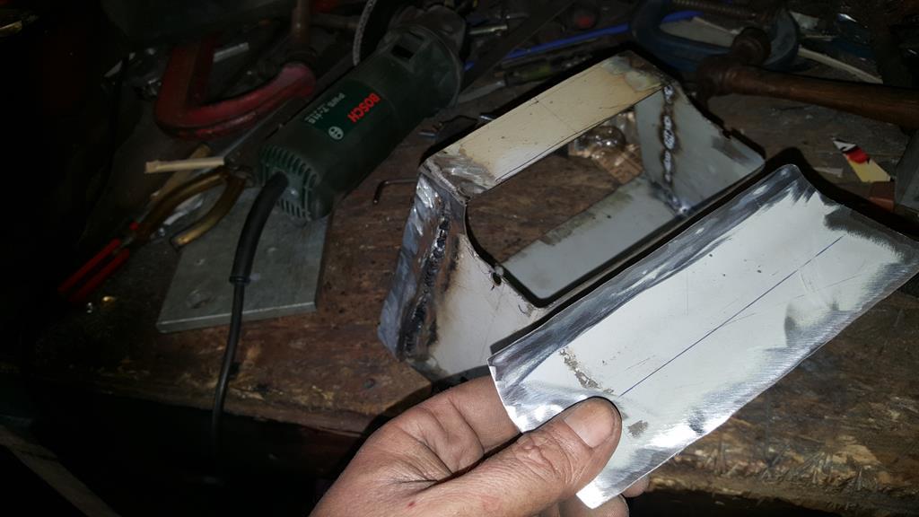 But before it was welded on the bulb holder plate was plug welded in.. Checking the bulb holder still fit.. They do  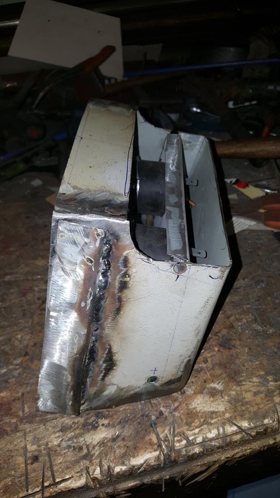 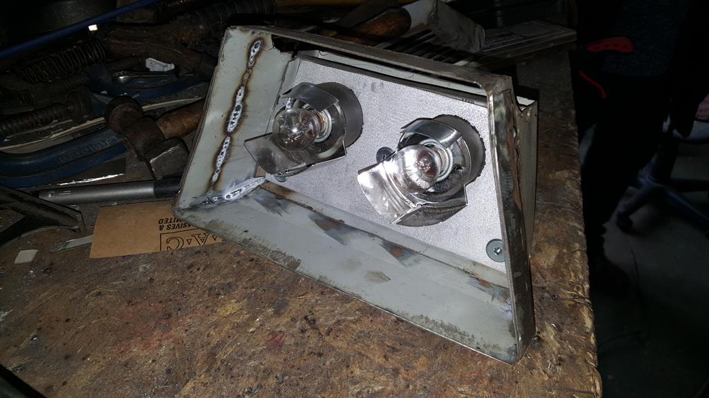 A view inside 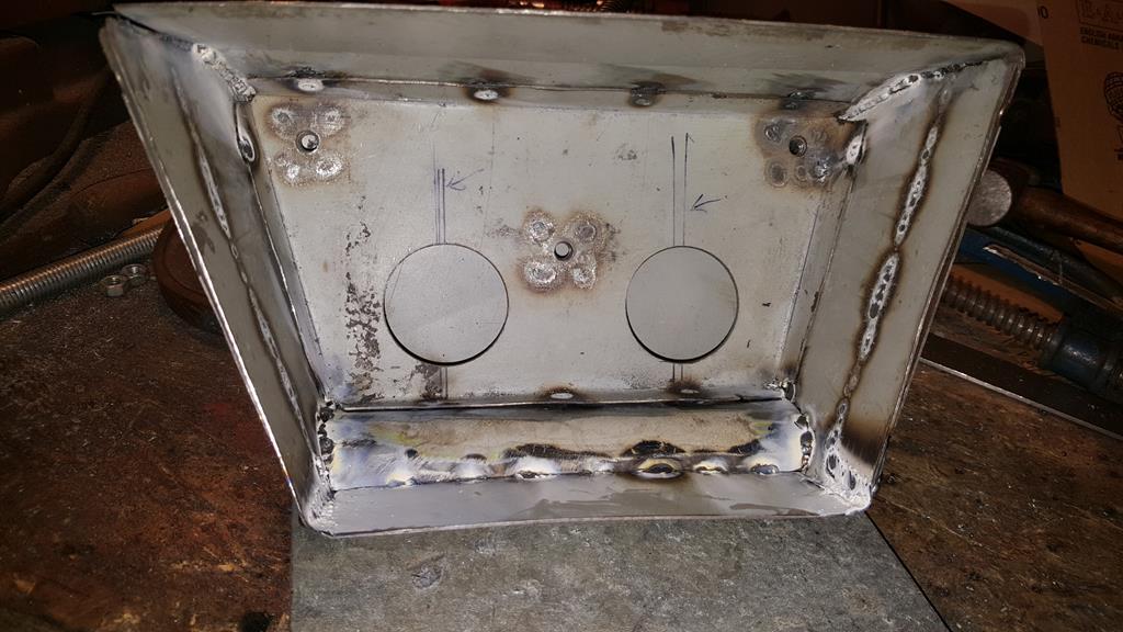 Lot's of welding and weld dressing to do.. 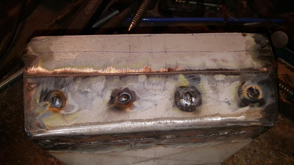 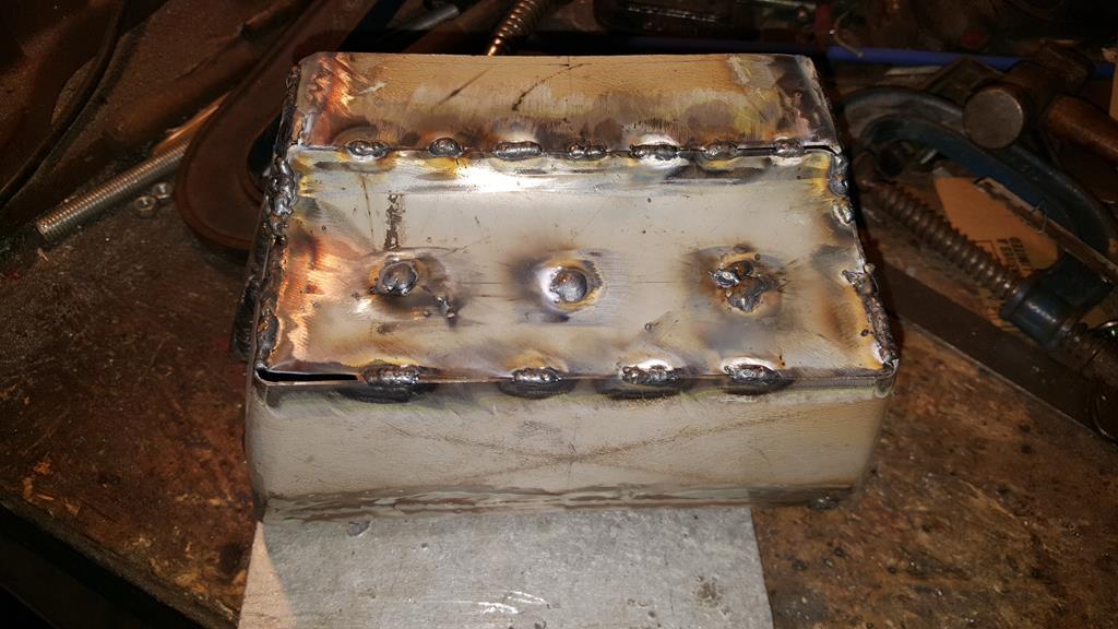 That looks better 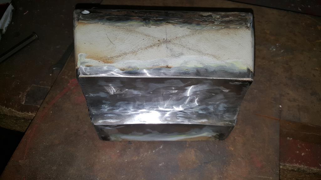 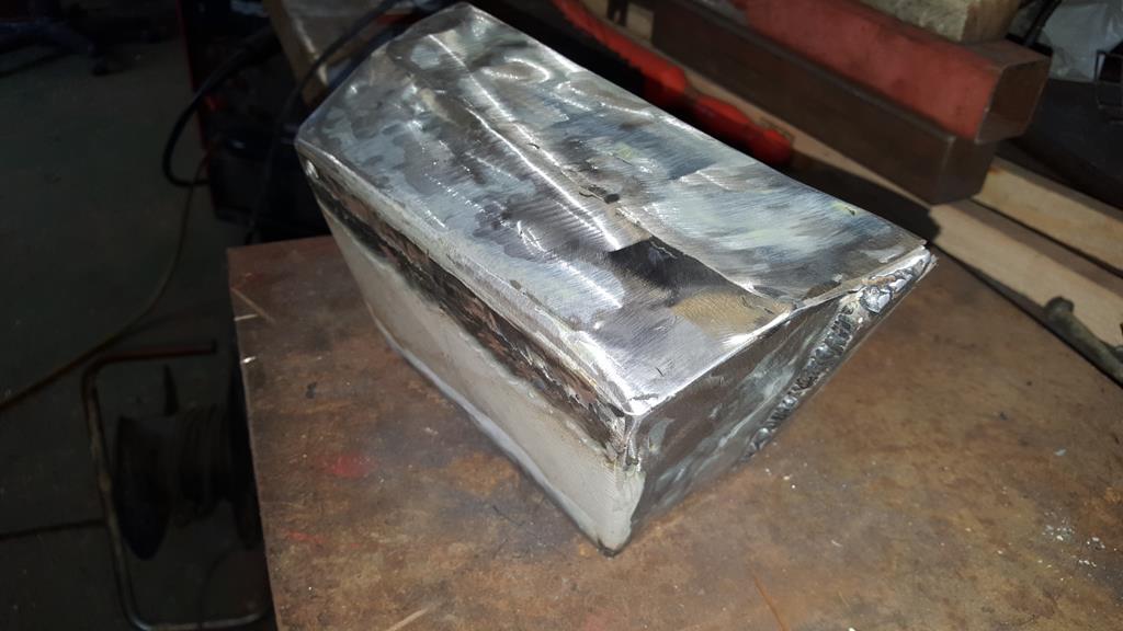 Best check it still fit's MadTrax!! It does  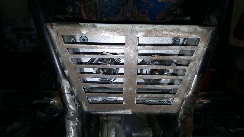  Some of the welds down the sides needed a few extra blobs of weld to tidy them up..  That will do for now, need some lunch.. |
| |
My YouTube Channel www.youtube.com/user/UkWheelHorseBlokeQuote - D'you know, it's people like you, doing totally brilliant and pointless stuff like this that gives me a little hope for humanity |
|
|
|
|
|
|
May 20, 2018 10:57:12 GMT
|
As I didn't have the sprockets at the time, and most of the jobs left to do involve having the 90'd drive in place, I was scratching around for something to do on MadTrax, so I decided to sort this little problem out! 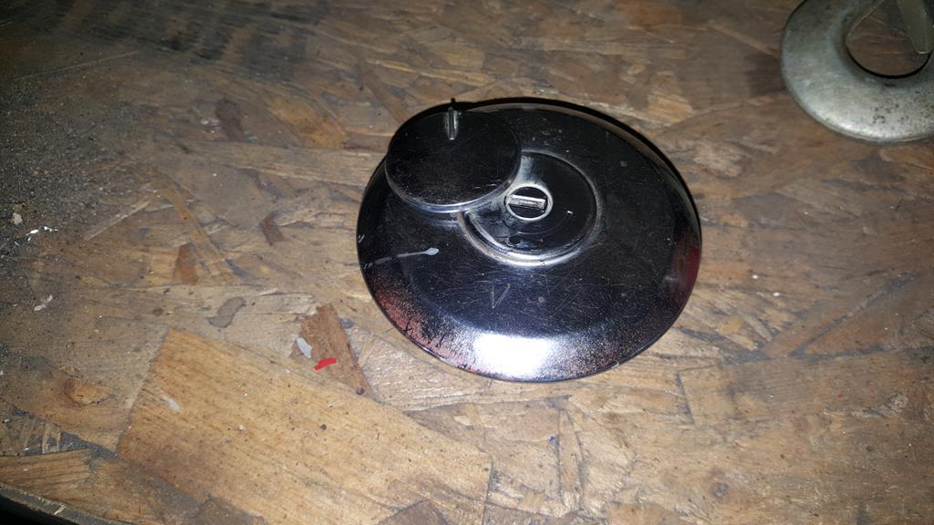 The problem being it should fit here (the tape is only to keep the dust etc out), but I don't have a key for it! 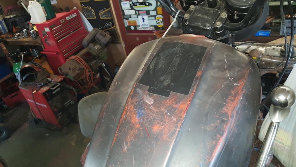 But I do have this tank from a Honda CX trike with a locking cap... I feel a bit of tank slicing coming up It would of been a shame to scrap the fantasic art work... 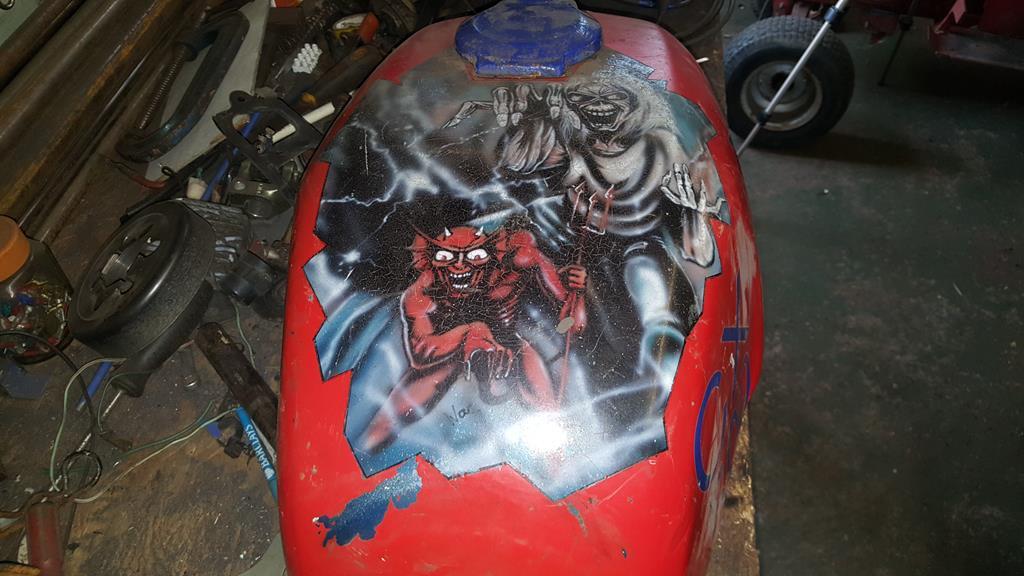 So I now have some more wall decoration  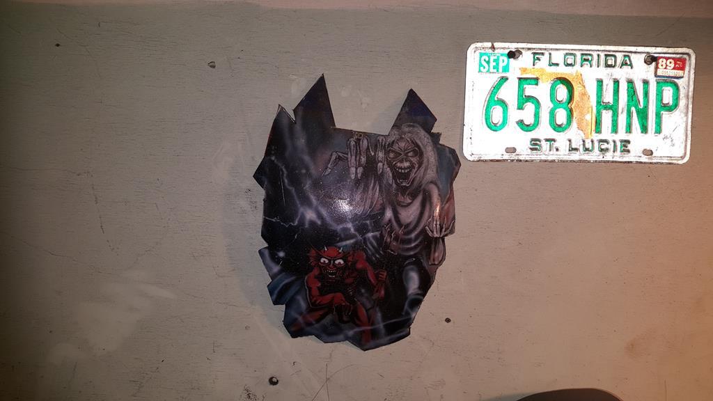 The filler hole section was cut from the CX tank, cleaned up and tried for size on MadTrax's tank. 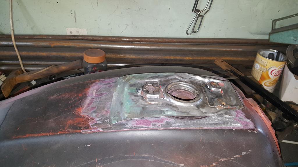 To mark where I would need to cut on MT's tank I needed to cut out a small section so the new bit would sit flat.. 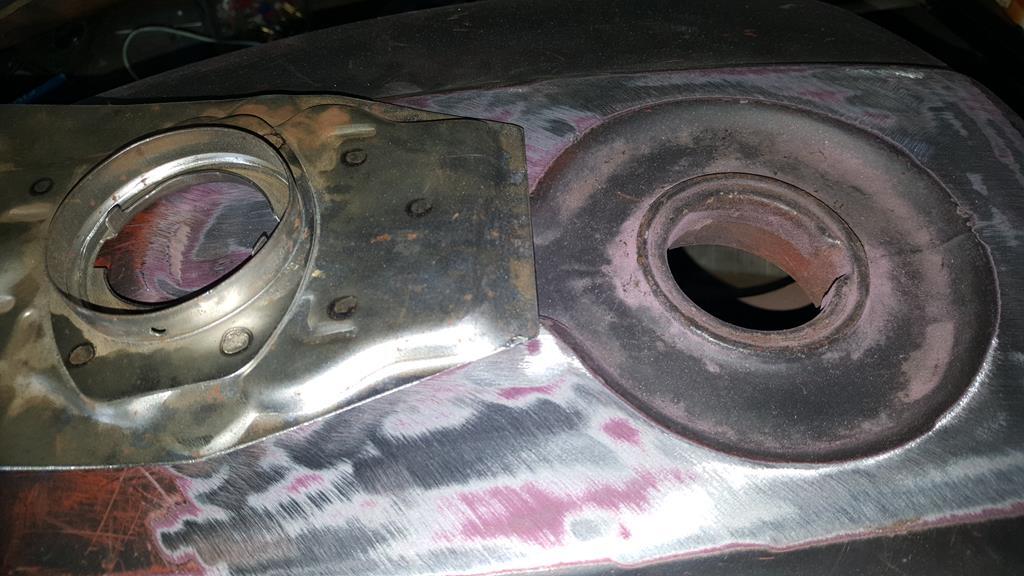 And here is the very same hole after being part welded back in! Yes my brain wasn't functioning to well that day and I cut too much out! 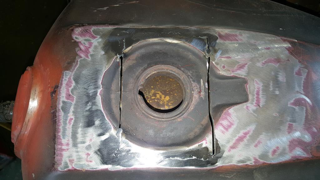 The correct size hole marked and cut out.. 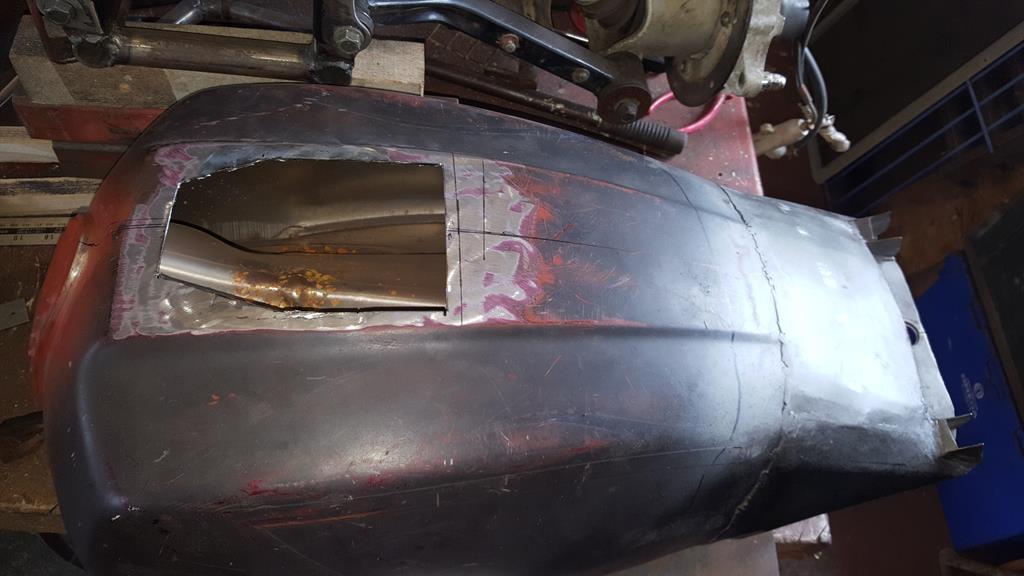 A test fit, only a few little tweaks needed.. 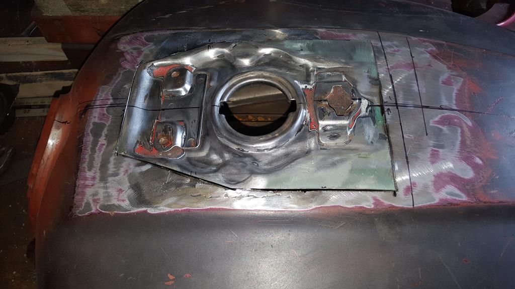 While I was getting on with the welding Rob was cleaning all the paint off the locking cap thingy. 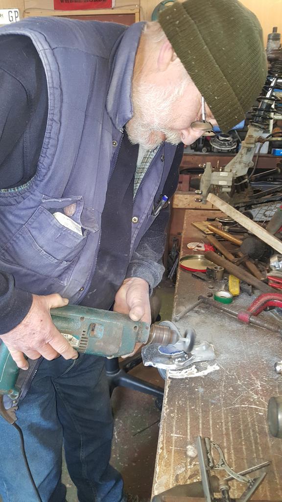 Quite a few layers of paint! 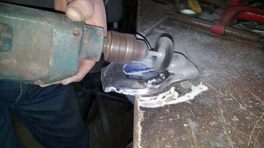 Ta-Daa 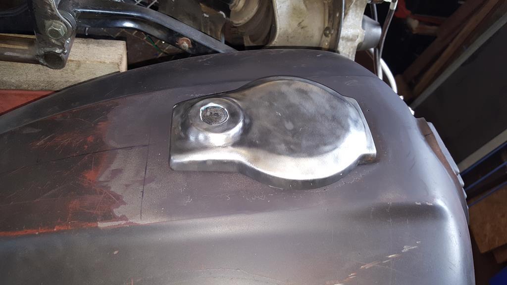 As you can see with the flap open it needs a little bit of filler work.. Not much though 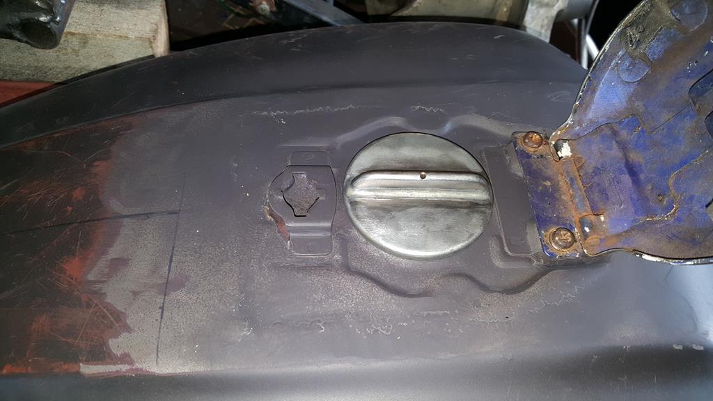 I gave it a quick coat of paint to help show up where I may of missed any welding... Here's one of the holes 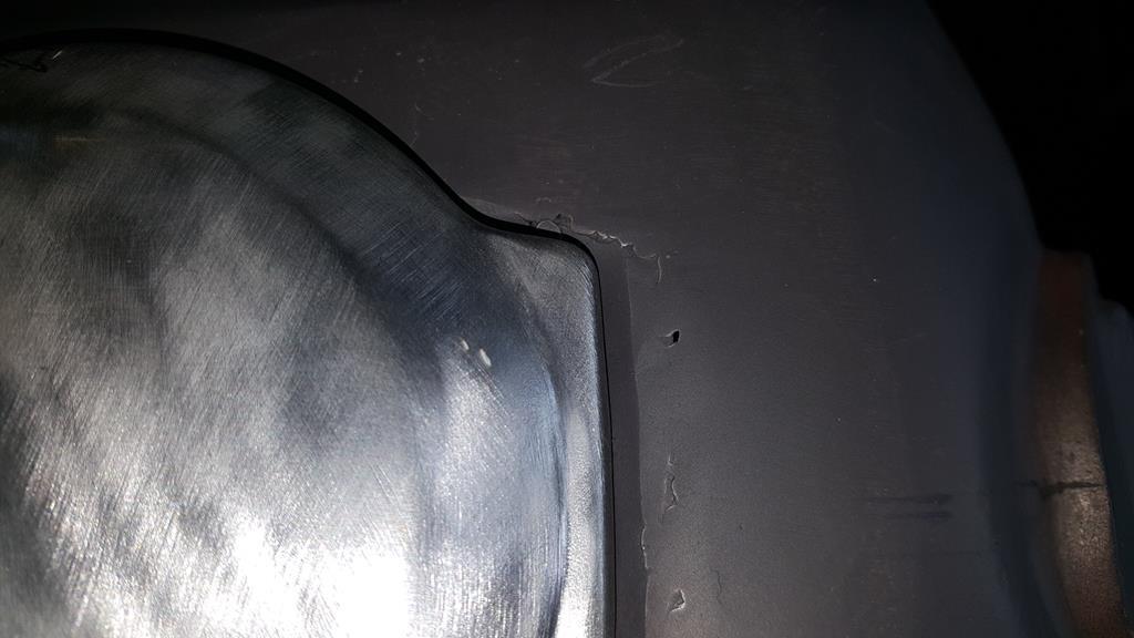 The new cap looks the part, I can't decide if it needs painting of just a coat of matt clear coat.. Time will tell 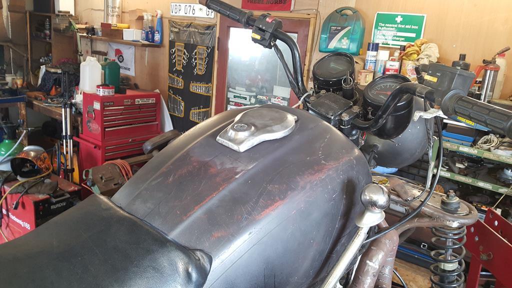 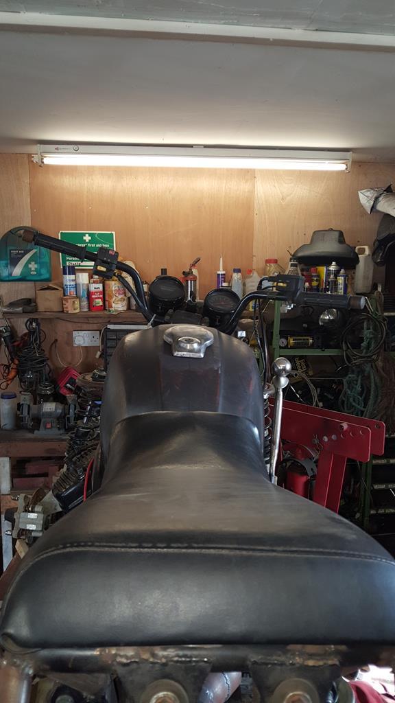 |
| |
My YouTube Channel www.youtube.com/user/UkWheelHorseBlokeQuote - D'you know, it's people like you, doing totally brilliant and pointless stuff like this that gives me a little hope for humanity |
|
|
|
|
May 20, 2018 10:48:21 GMT
|
As ever... Thanks George Hi Guys n Girls, quite a big update for you.. Back to the 90'd drive thingy from the Honda Silverwing that I'm using to turn the drive around.. On the bike the rear wheel would of bolted to this bit. 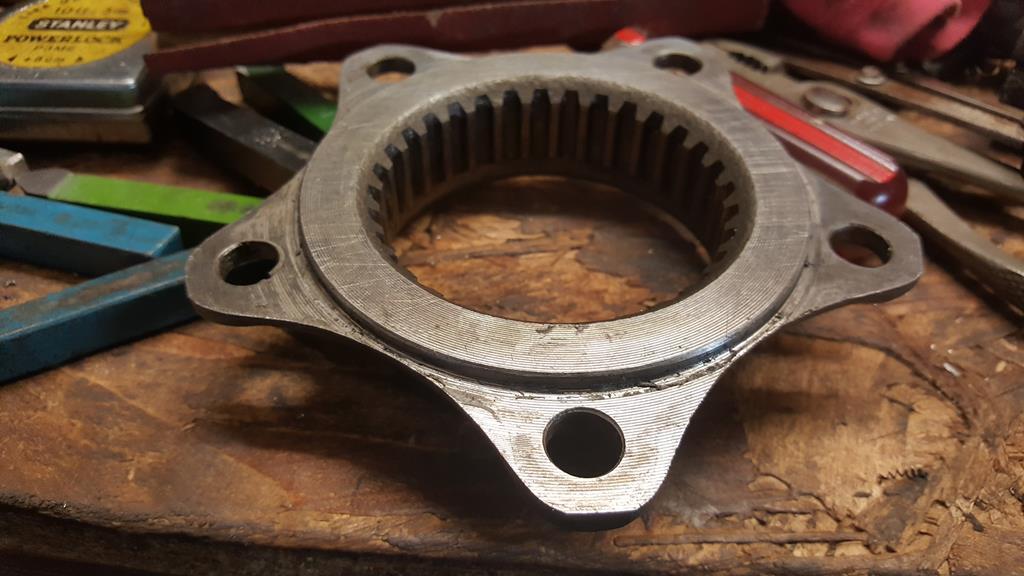 But I need to put the drive from the gearbox into the 90'd drive from this way... But how to bolt a sprocket to it? Starting with a slab of 10mm thick steel and a photo that won't turn the right way! 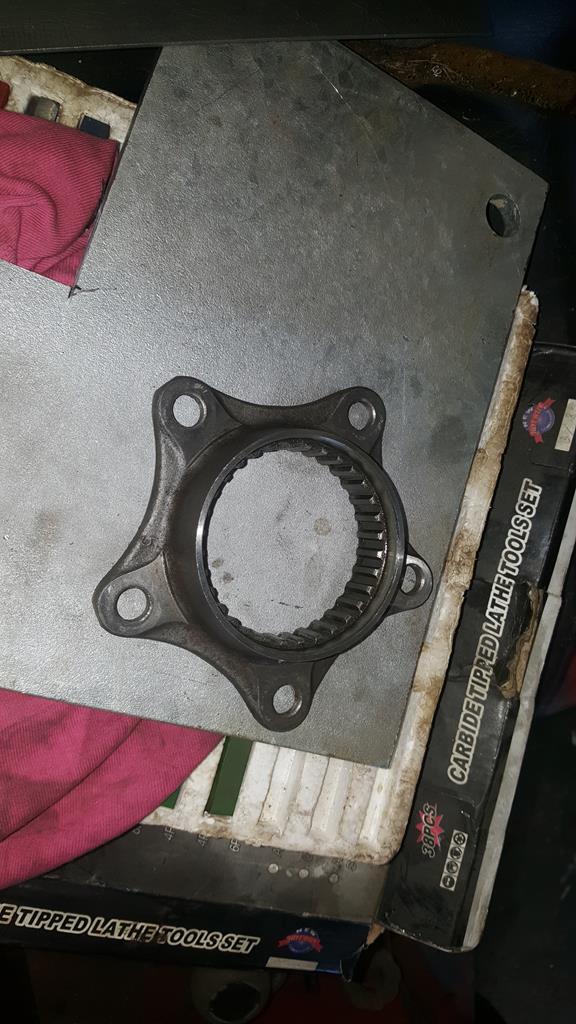 To bolt the splined bit flush on the plate I had to cut a wide groove in one face. 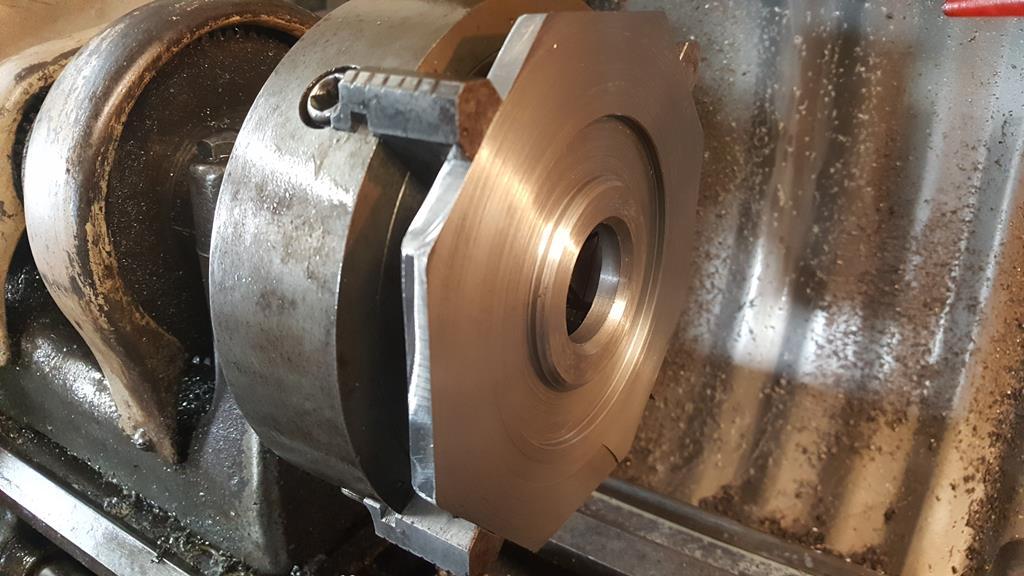 That looks good. 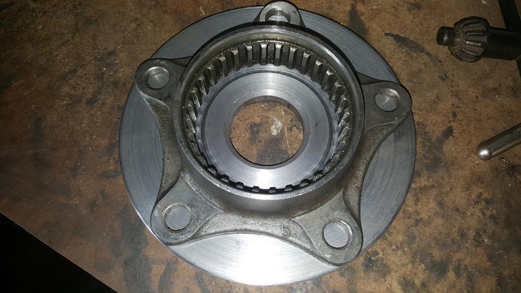 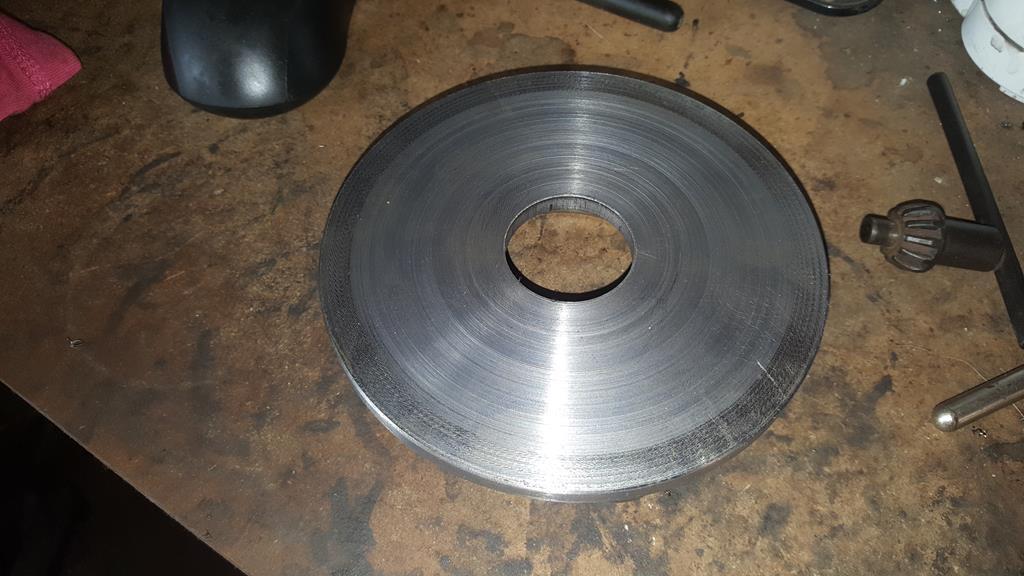 To fit a sprocket to all this a shaft is needed.. This will do. 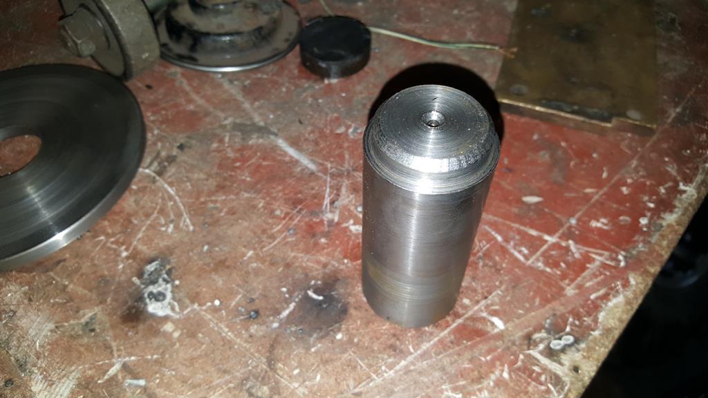 It fits in the circular plate like this, the tapers will be filled with weld. 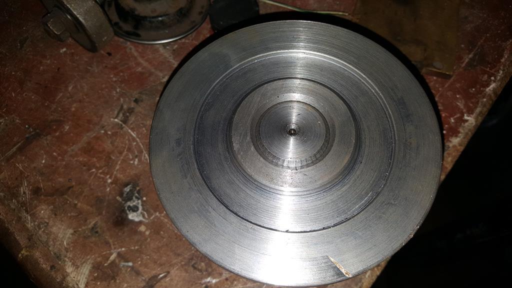 The other side will get welded on and the welds turned down to look good on the lathe.. The shaft has been made over sized as I don't know the measurements until I get the sprockets and try to fit the whole thing in place. 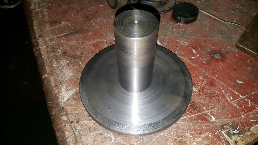 This is quite a big "whole thing" to fit!  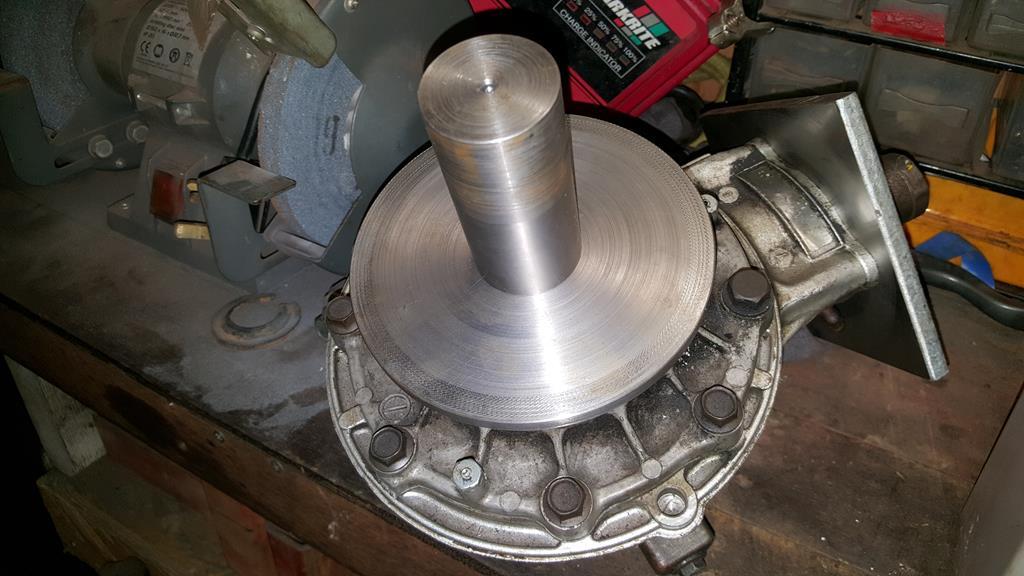 Nows a good point to drop in the next video.. |
| |
My YouTube Channel www.youtube.com/user/UkWheelHorseBlokeQuote - D'you know, it's people like you, doing totally brilliant and pointless stuff like this that gives me a little hope for humanity |
|
|
|
|
|
|
Spotted in Hawkhurst, Kent yesterday afternoon.. No idea what engine was fitted but it did sound nice and certaily flew across the lights when they changed 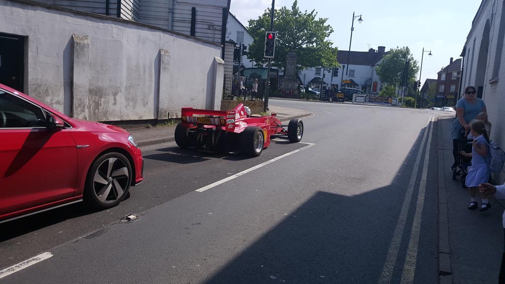 A closer up. 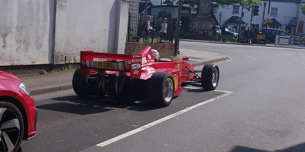 |
| |
My YouTube Channel www.youtube.com/user/UkWheelHorseBlokeQuote - D'you know, it's people like you, doing totally brilliant and pointless stuff like this that gives me a little hope for humanity |
|
|
|
|
|
|
Plenty more lathe work to go, I needed to make something that would fit over this stepped shaft on the TB input side of things. The reason being I need to fit a sprocket to the shaft but there isn't a keyway for location, only splines at the outer end.  Lot of time was spent with some 40mm bar to create this. 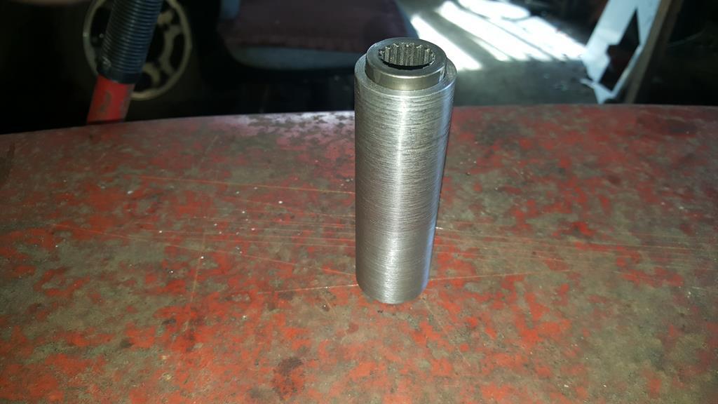 Outer splines presure fitted to the sleave one end, it will be welded also. 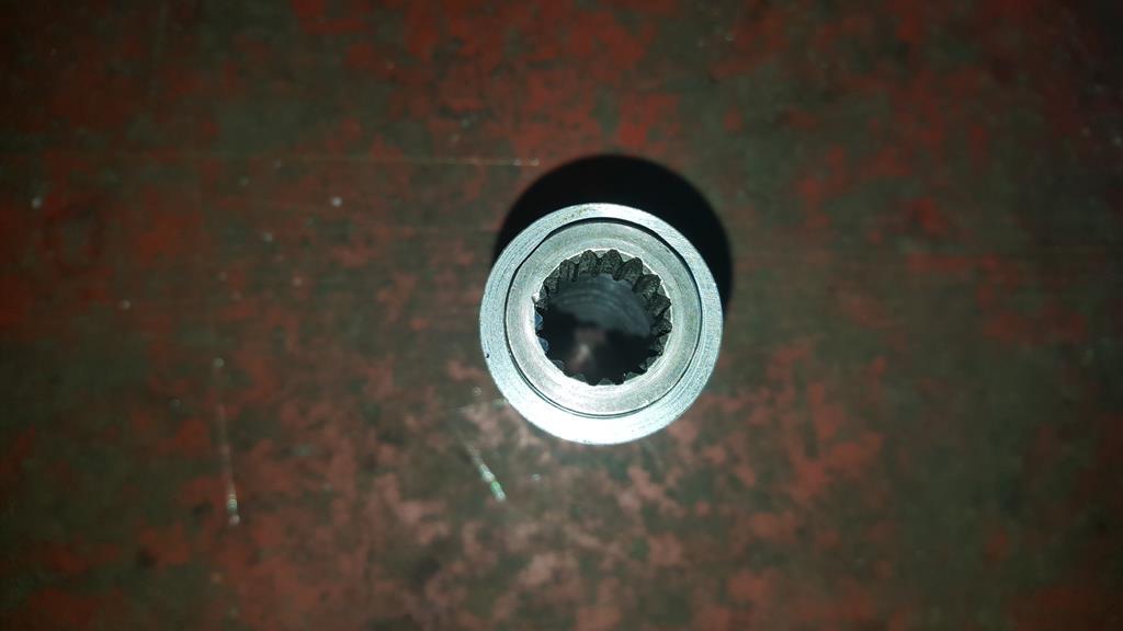 Stepped inside to fit the shaft. It would of been nice to cut a taper inside to match taper on the shaft, but don't have the tools to do it.. 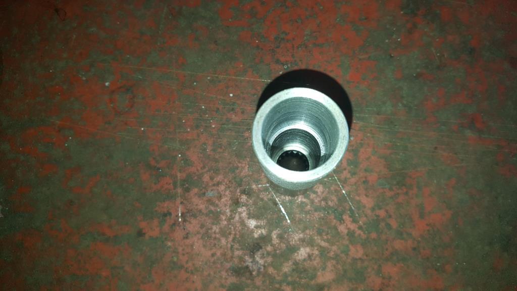 Splined sleeve bolted on the TB shaft, the sleeve walls are not thick enough to cut a keyway so the sprocket will have to be welded on. 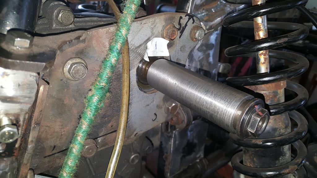 That will do for this update, I do have more to post but I seem to be missing a few photo's.. I must remind myself to take some more pic's tomorrow.. |
| |
My YouTube Channel www.youtube.com/user/UkWheelHorseBlokeQuote - D'you know, it's people like you, doing totally brilliant and pointless stuff like this that gives me a little hope for humanity |
|
|
|
|
|
|
It was at this point I started to have a few of those "Groundhog day" sort of moments! Having worked out how to make a shaft that fit's over the gearbox splines, has a bearing at the other end and also has a sproket in the middle, I proceeded to make a mess of things 3 times! Attempt 1... Having just checked the bearing fit I forgot to tighten the tailstock back up for the final cut! The result was some nice deep gouges! (not seen in this pic as I trimmed some more off to check which tools cut best) 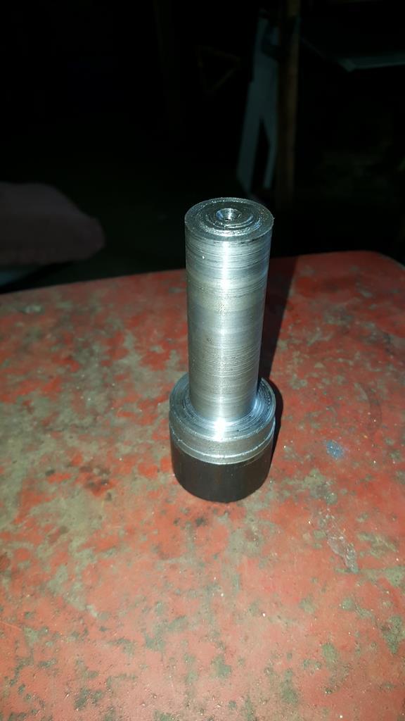 Attempt 2... Counted twice what I should of done and took too much metal off making the bearing a loose fit! 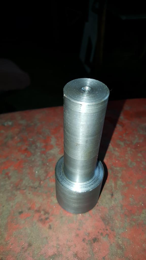 Attempt 3!!! All was going well until I broke a small drill bit off about 1/2 inch in!! No way of getting it out! 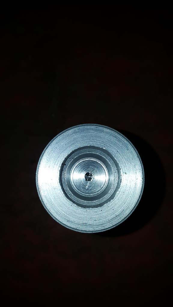 Attempt 4... It may need a bit of work at this point!  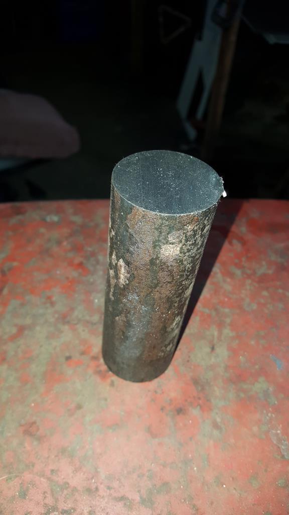 And attempt 4 in it's finished (and correctly sized) state. Phew... I hate having to redo stuff! 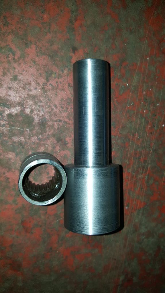 Not a perfect finish inside, but the measurements are right. 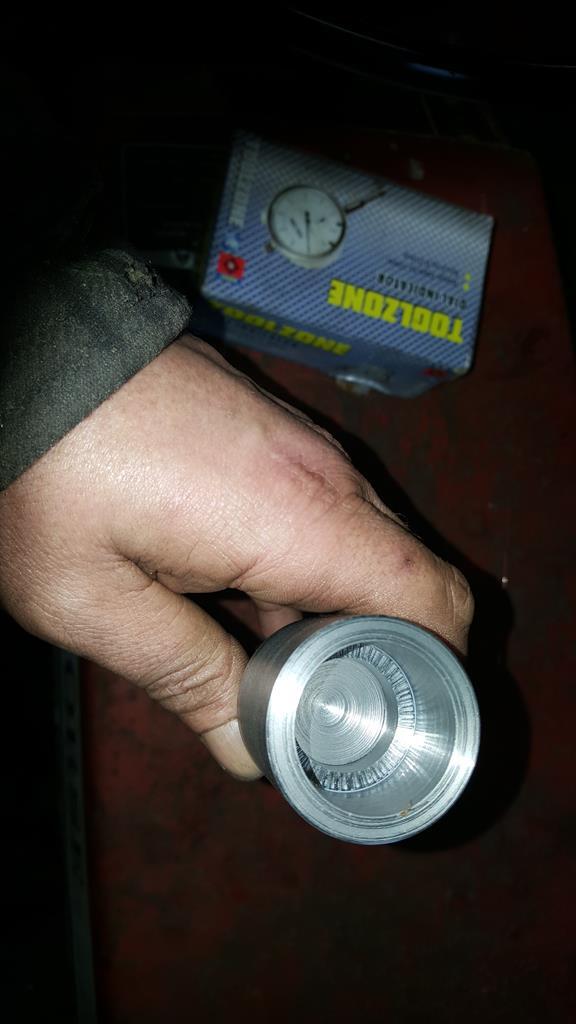 The splined bit pressure fitted, a nice tight fit.. It will be welded on then the welds and overhang will be tidied up on the lathe. 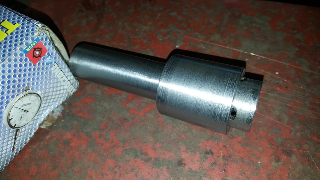 And finally with the bearing, I still need to buy the sprockets but as they will need boring out to fit the shaft I could get on and make this part.. 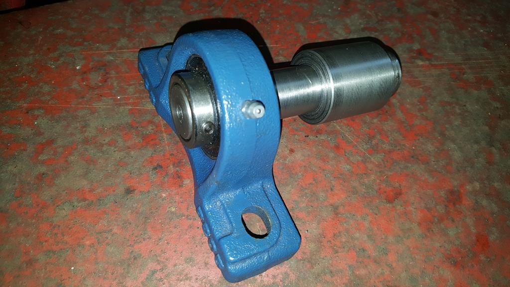 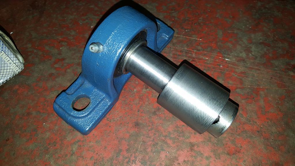 |
| |
My YouTube Channel www.youtube.com/user/UkWheelHorseBlokeQuote - D'you know, it's people like you, doing totally brilliant and pointless stuff like this that gives me a little hope for humanity |
|
|
|
|
|
|
Thanks Mikey, happy you like it love the rear light, and the fuse box holder Thanks Spiny, the rear light has been a lot of work but worth it. Just spent a lot of the day reading this thread from the start. Great stuff 😎 Hi Ric, I guess you had quite a few hours to spare as it's a long read, or were you just trying to escape all the Easter nonsense? Thanks for reading right through the thread anyway In case anyone is wondering, no I've not been eating since the last update, life just has a nasty habit of getting in the way at the moment! It was at this point my hands were not too happy about beating and shaping metal, so I thought I do something less hand straining on the lathe.. This UJ was part of the drive system when I thought lot's of UJ's were a good idea! 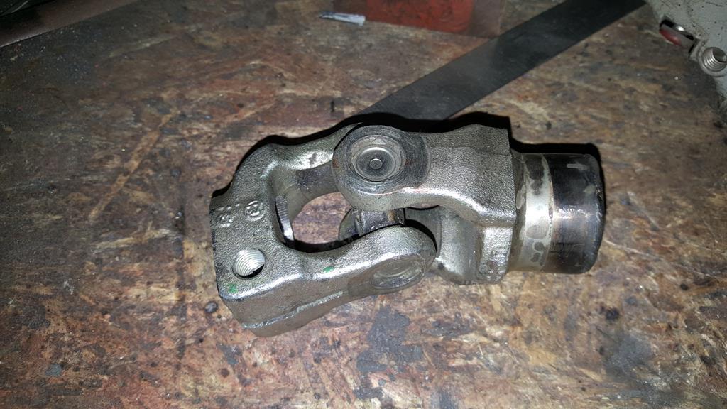 The problem is I had also welded a splined bit inside one end, and the said splined bit fit's the splined shaft that comes out the bike gearbox! 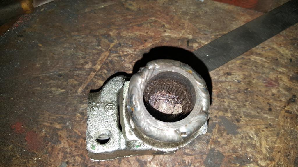 It's a shame to chop a UJ up, but when needs must.. Here's what's left of the UJ on the lathe having just broken through one end so I can get to the splined bit. 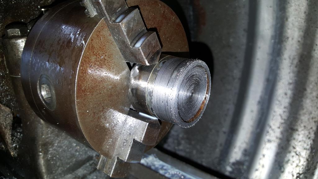 The hidden splines.. 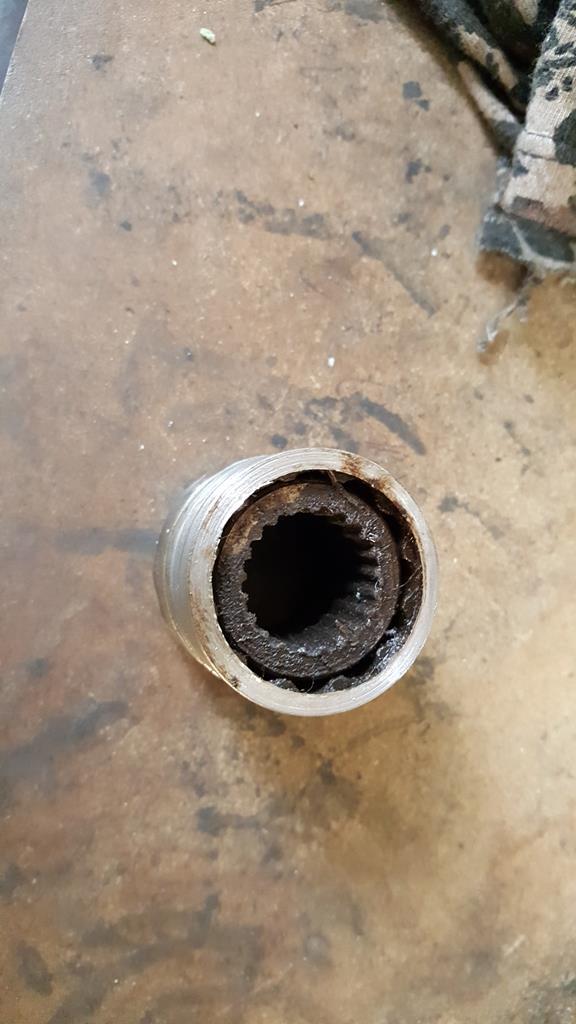 Knocked out with a hammer and drift. 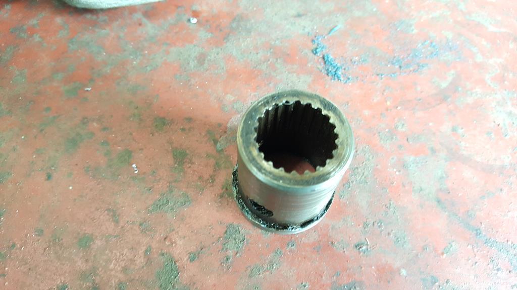 All that work for this little bit of steel slid on the gearbox shaft! 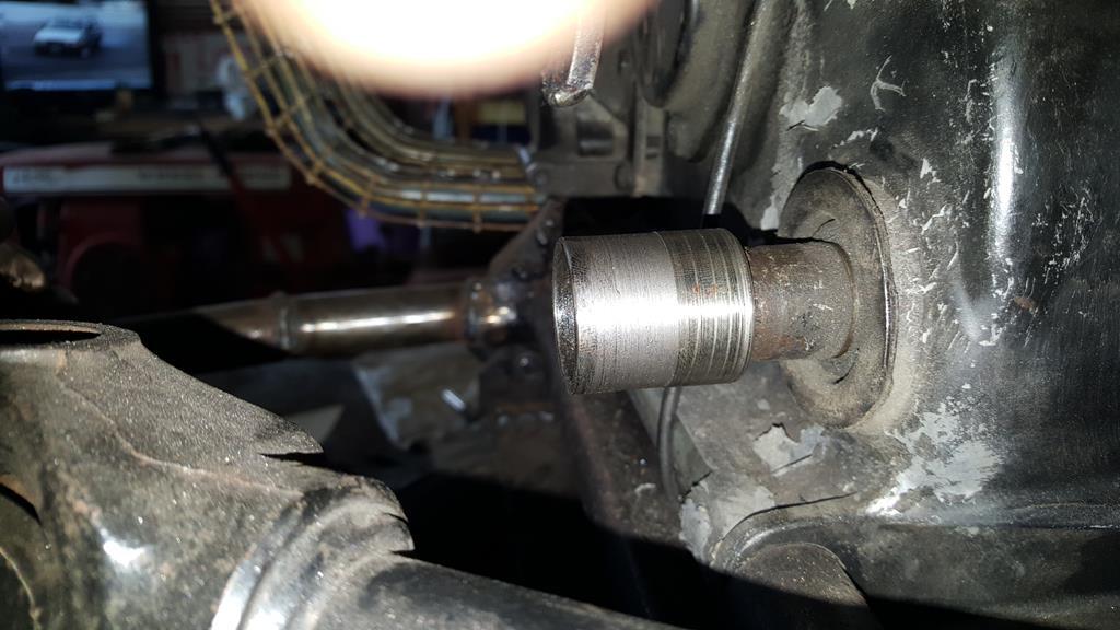 Time to think about mounting this large lump of 90'd drive! 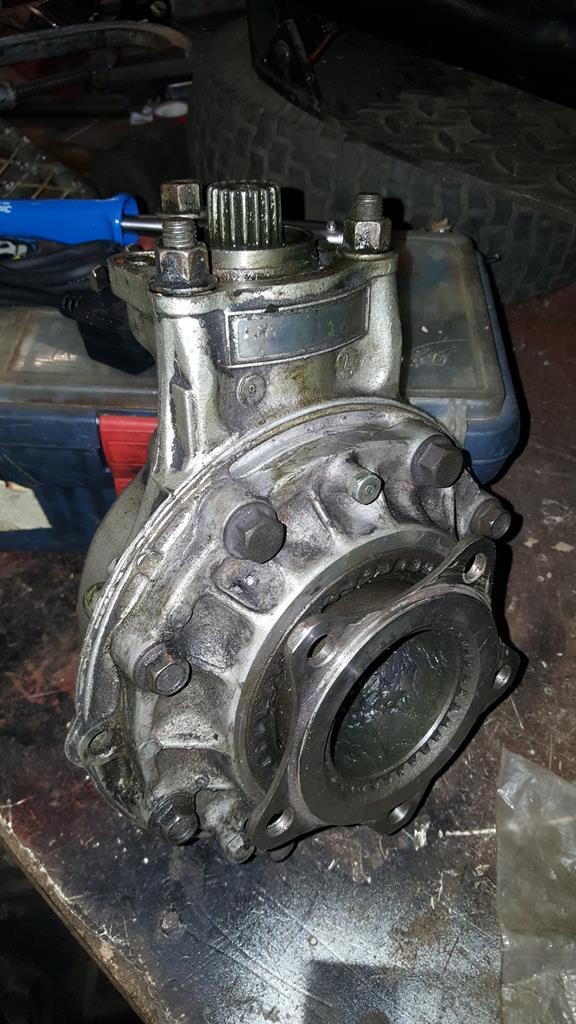 This 10mm thick steel plate should be strong enough 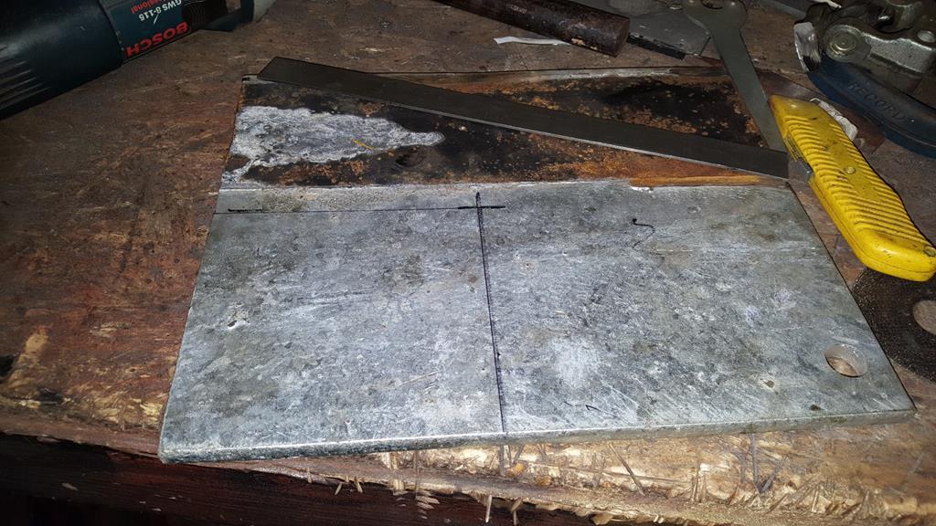 Lot's of lathe and drill action later... (all the action coming up in the next video). 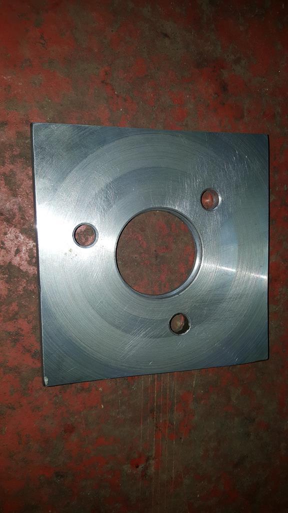 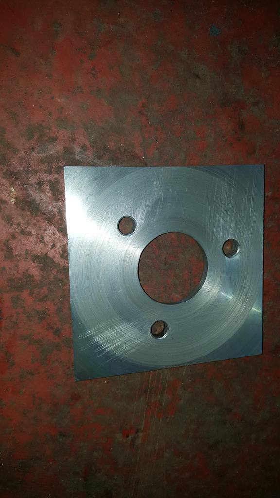 Bolted on.. 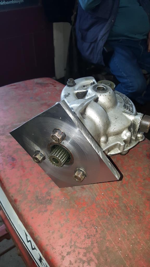 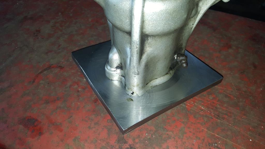 |
| |
My YouTube Channel www.youtube.com/user/UkWheelHorseBlokeQuote - D'you know, it's people like you, doing totally brilliant and pointless stuff like this that gives me a little hope for humanity |
|
|
|
|
Mar 17, 2018 18:36:00 GMT
|
Back to the rear light and I needed some sheet steel to make it from. This will do..  Yes it came from our old tumble drier and still has some fluff on it to prove it  A grinder with a 1mm disc was used to cut the long slices, a sharpened screwdriver (yes it was a very old one of which I have many) was used to chop the ends out. 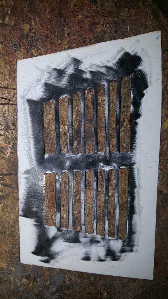 Lot's of time spent with a file later and the lens almost fits. 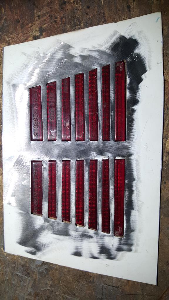 Time to bend the edges round, wanting a nice curve some bar stock was used for beating around. 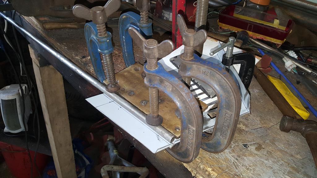 Taa Daa. 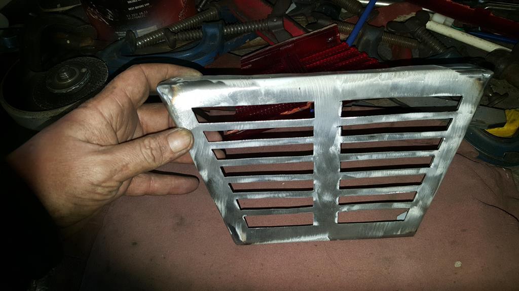 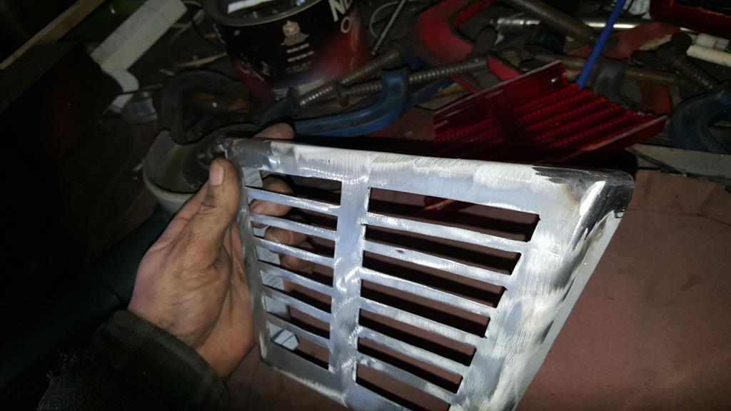 A lens check.  "Let there be light"  And held in postion..  More to come later, food is needed. |
| |
My YouTube Channel www.youtube.com/user/UkWheelHorseBlokeQuote - D'you know, it's people like you, doing totally brilliant and pointless stuff like this that gives me a little hope for humanity |
|
|
|
|
Mar 17, 2018 18:11:22 GMT
|
Evening all, more of an update for you starting with a video.... Lot's of timelapse bits Back to the headlamp but only very quickly.. When it came to wire the lamp in I found there wasn't enough space around the outside of the bulb holder to run the wires,so three holes were dilled and then slotted to feed the wires through.  Time to turn to the other end of MadTrax.. Starting with a cardboard template.. 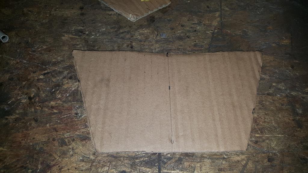 Which fits about here. 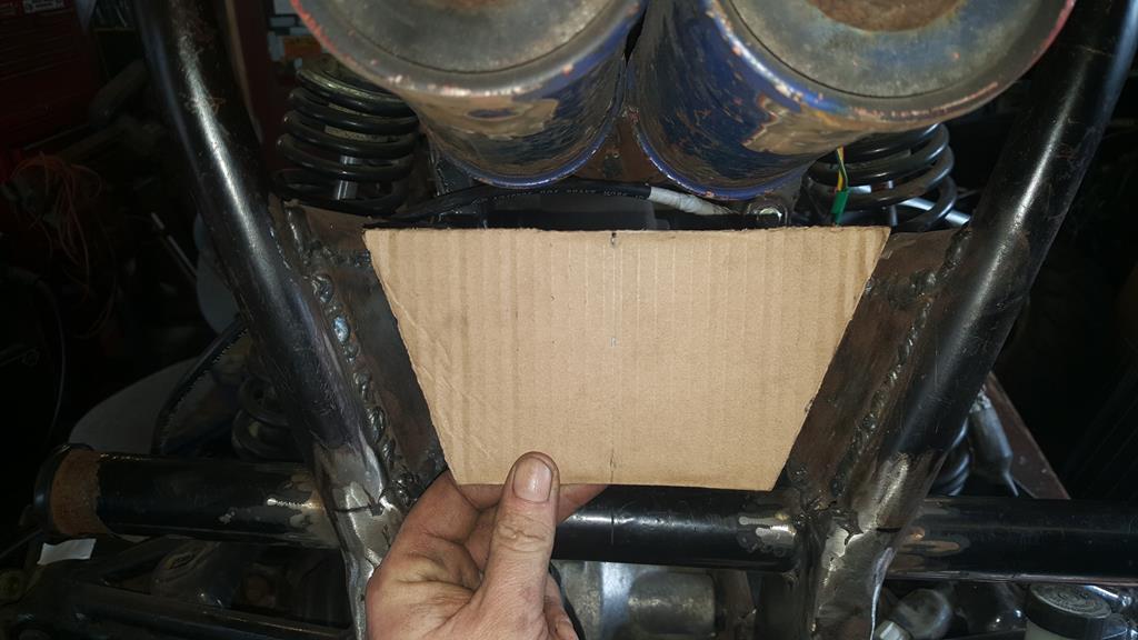 I'm sure you will of guessed by now it's for a rear light.. Even though I've no plans to put MadTrax on the road it needs a rear light to balance out the front light.. Not having any rear lights that will fit I need to make my own, starting with this Honda Silverwing light lens. 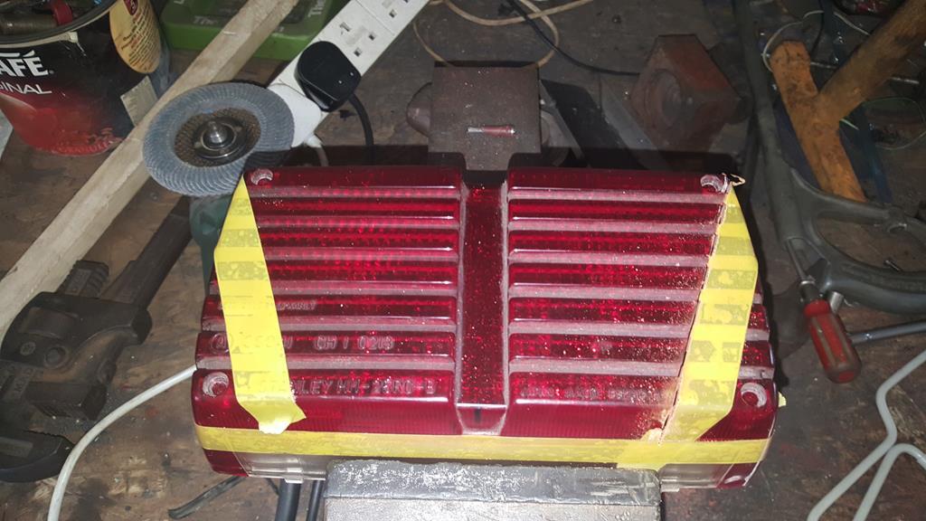 Trimmed to shape including the lens inside. 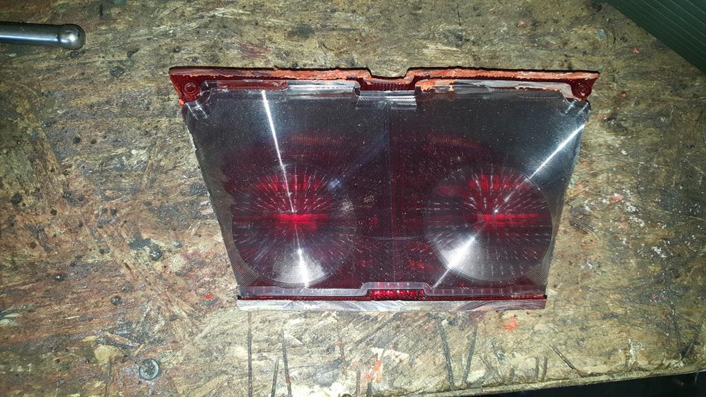 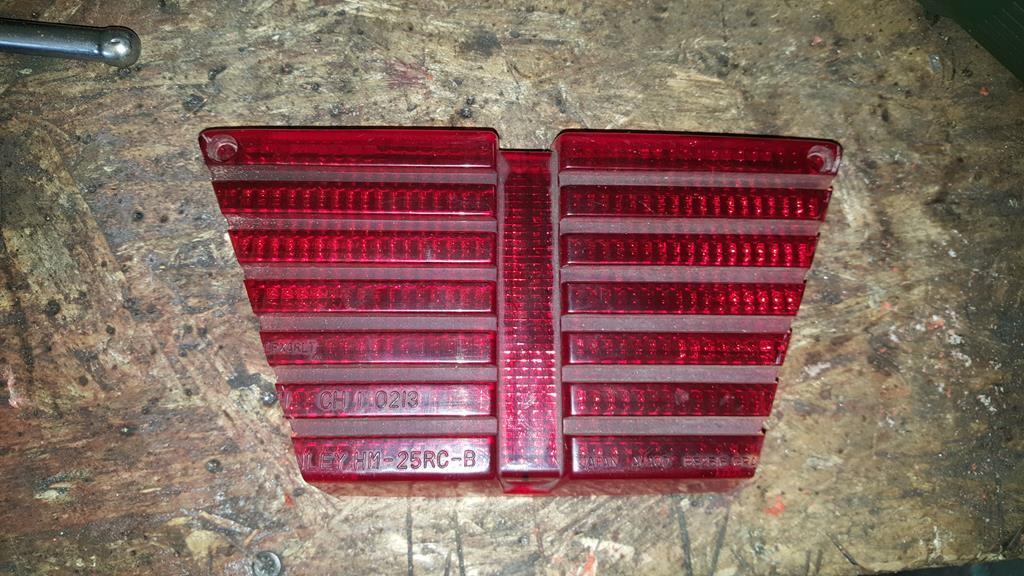 Hard to hold in position and take a picture! 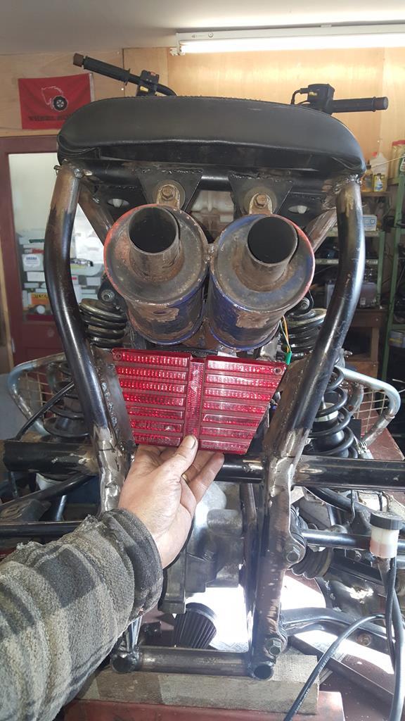 I have an idea on how I want the rear light to look, template time.. Rubbing dirty fingers on paper to make some marks and then cutting out didn't work too well.. 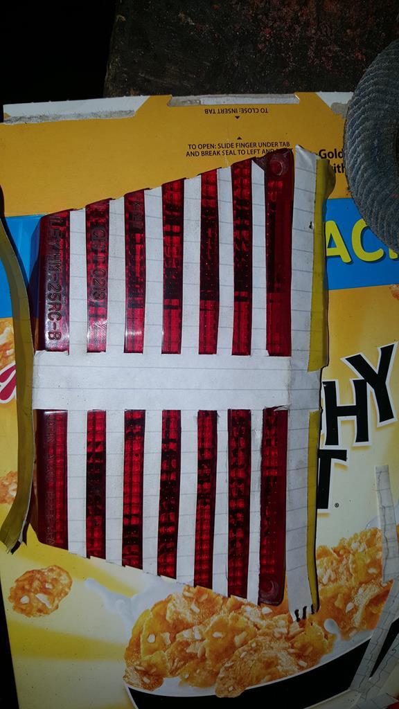 Template number 2 involved cutting lots of bits of cardboard but it looks much better and is much more usable as an actual template Turning this into steel is going to be fun 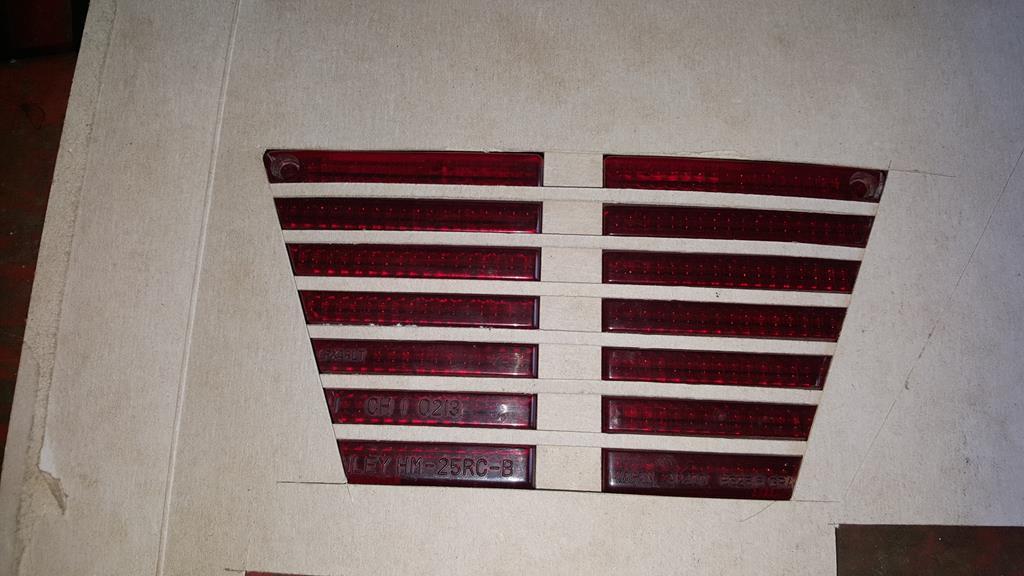 The transfer box gear stick needed a tweak so it wasn't in the way of any knees, so it was moved in by an inch, lengthened and a new hip and groovy knob was put on the end It needs a little tidy up but it looks good 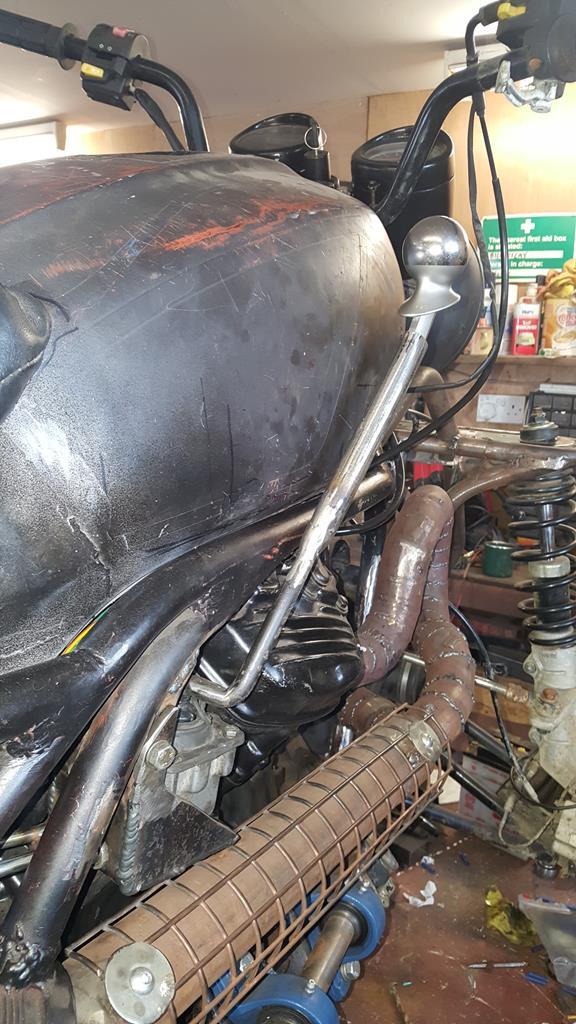 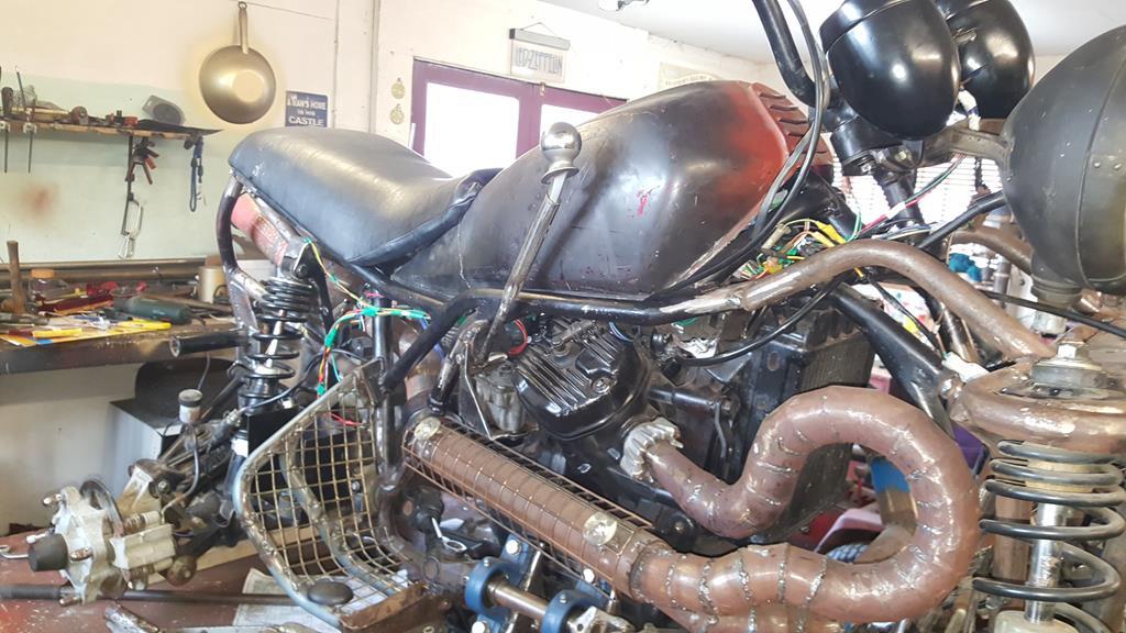 |
| |
My YouTube Channel www.youtube.com/user/UkWheelHorseBlokeQuote - D'you know, it's people like you, doing totally brilliant and pointless stuff like this that gives me a little hope for humanity |
|
|
|
|
|
|
As ever, great stuff... Thanks George. With the 4 wheel drive bit wired in, the time had come to think about lights starting with the er.. headlamp.. Not having the correct bulb holder (which would of been for a really old style bulb anyway) I had this problem to overcome! 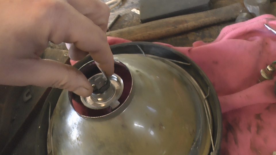 I had an idea on how to solve the er..gap problem but not the materials until Nigel found me this old pully.. Thank mate 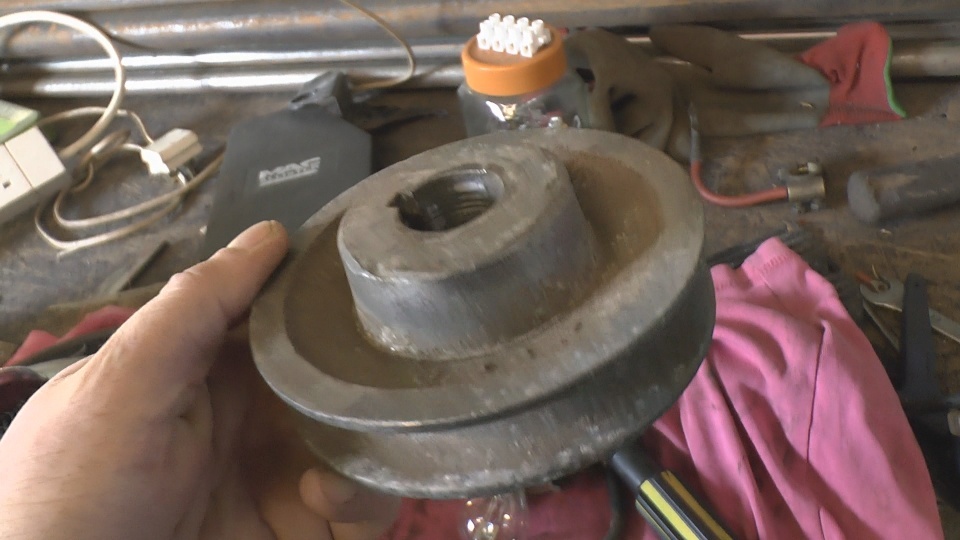 No photo's of all the lathe stages (plenty of that in the next video) but the pulley ending up looking like this. 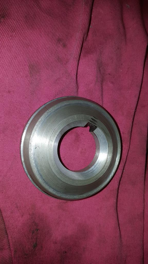 The shallow slots were done with a milling bit in my pillar drill. Not ideal as the bed does try to move sideways! 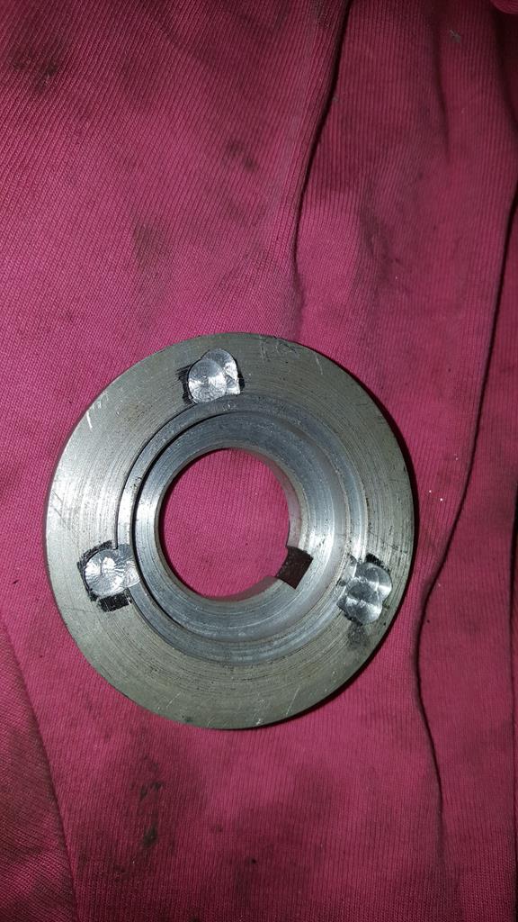 The bulb pokes through like this. 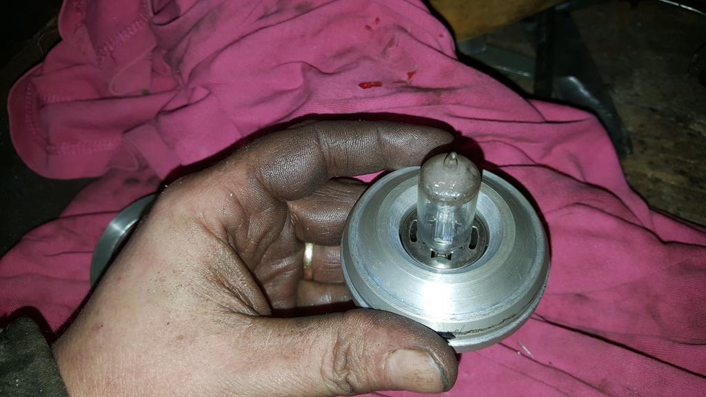 Then the whole thing drops into the back of the lamp bowl. The little black slot through the bowl is a handy bolt hole, as is the one the other side. 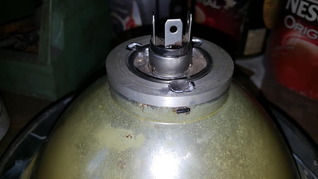 Now something to hold the bulb to the holder. Starting with this.. Thanks again Nigel 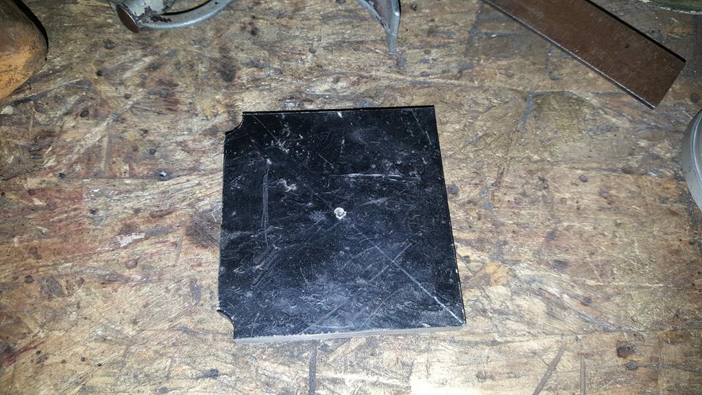 It was turned into this.. 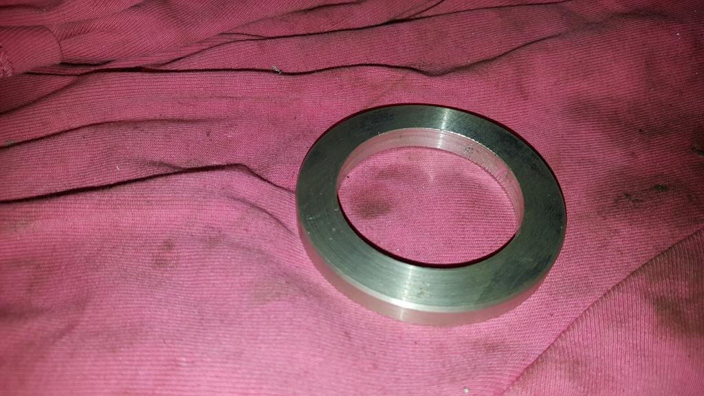 Which of course fits here.. 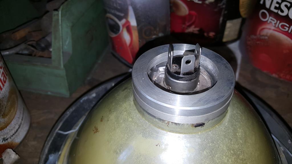 I found some nice small bolts to use but I didn't have a tap to cut a thread..... So I made one 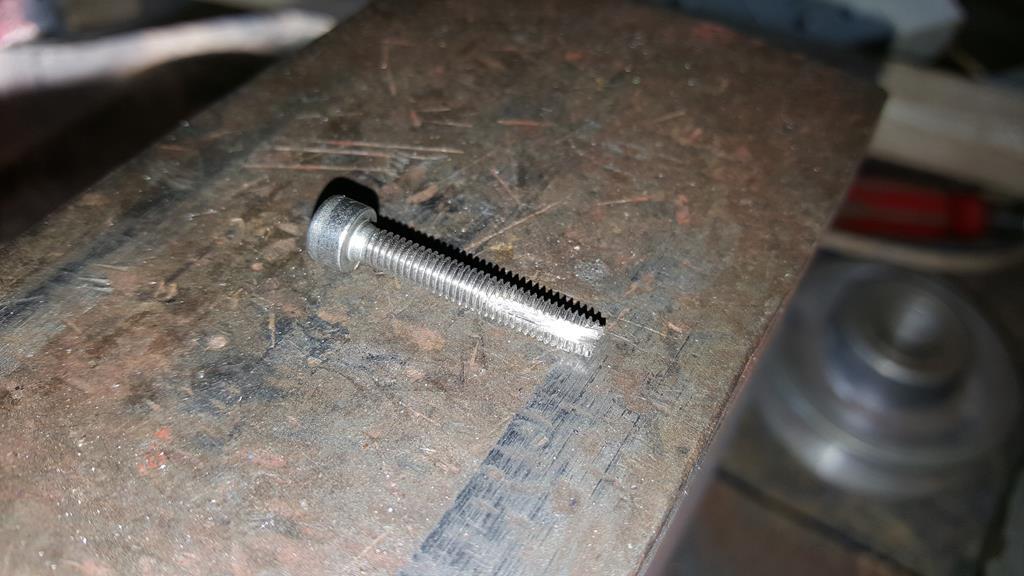 Best test it.. Yep it works... 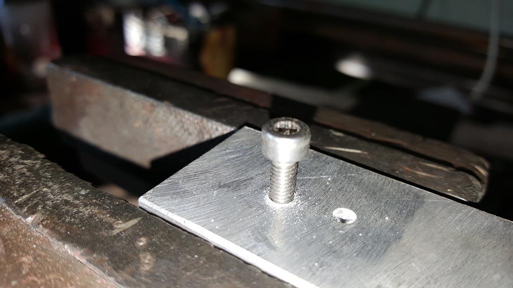 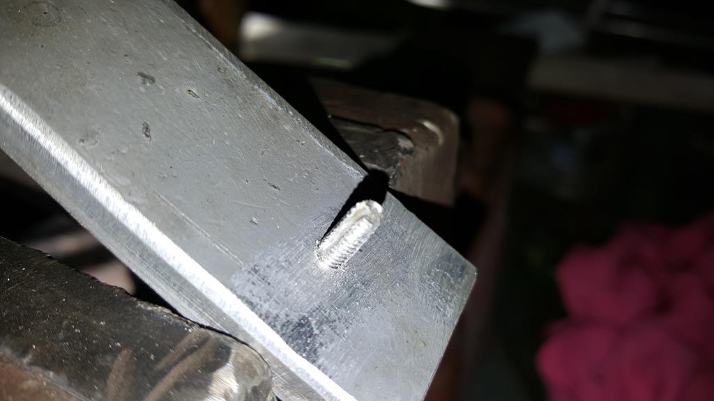 Lots of drilling, thread cutting and countersinking and bolt shortening later.. 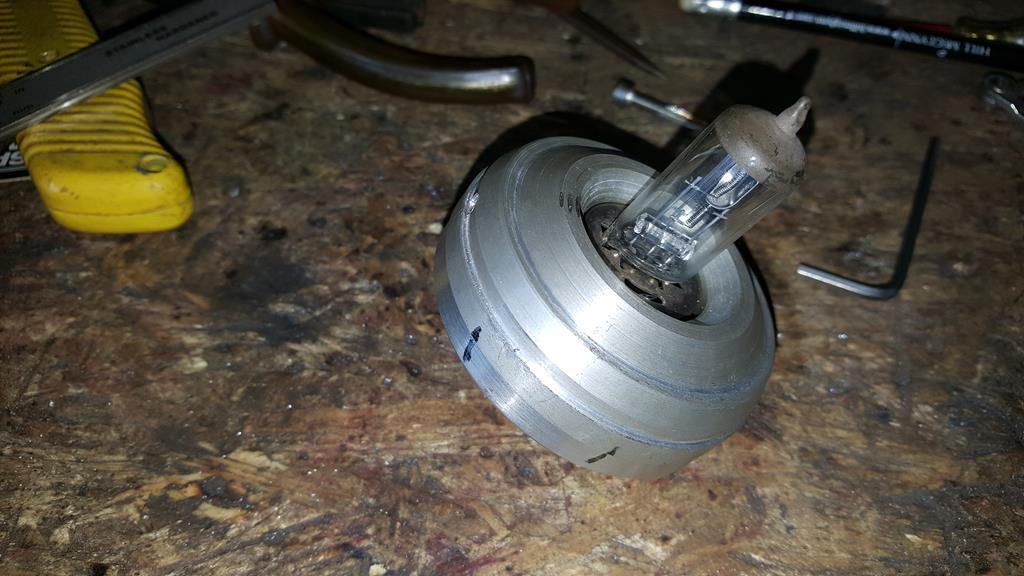 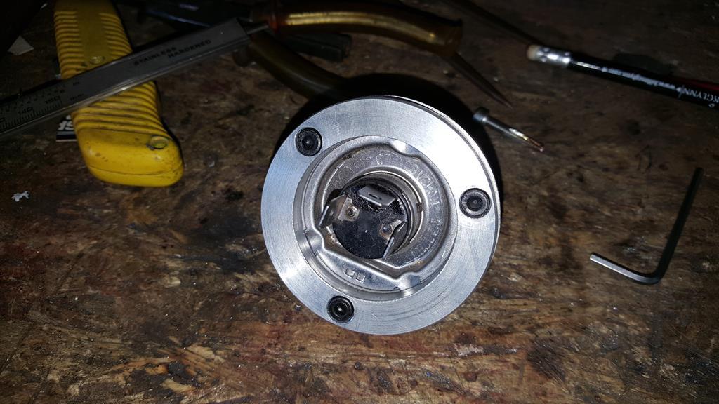 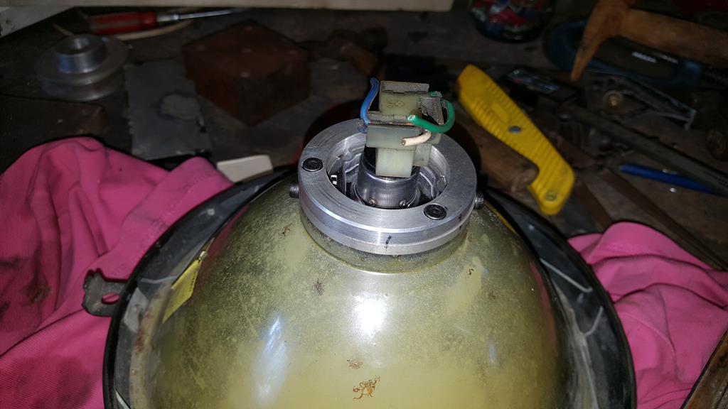 Tad-Daaa A lot of work for something that won't be seen 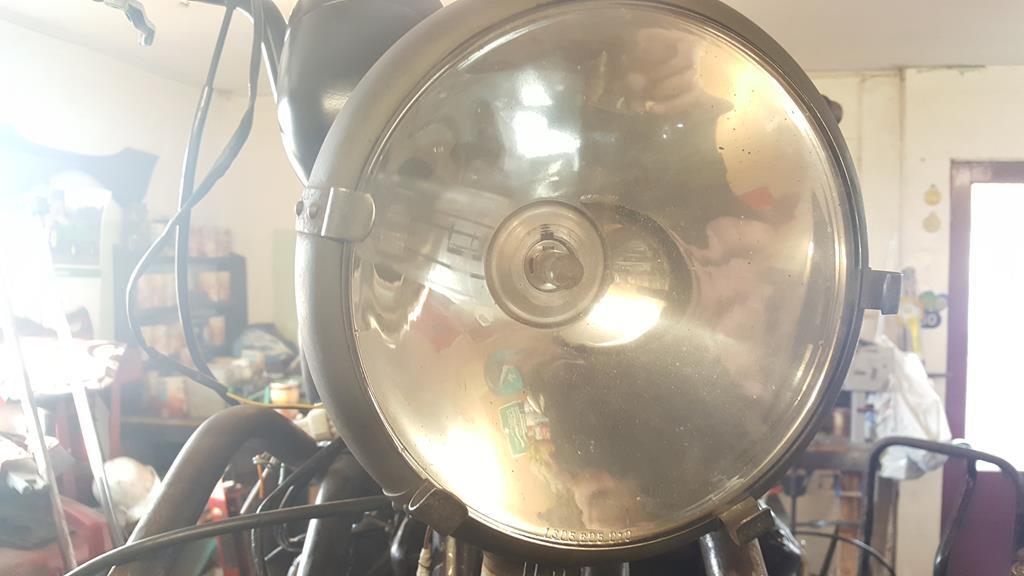 |
| |
My YouTube Channel www.youtube.com/user/UkWheelHorseBlokeQuote - D'you know, it's people like you, doing totally brilliant and pointless stuff like this that gives me a little hope for humanity |
|
|
|
|
|
|
Feb 25, 2018 11:51:56 GMT
|
Now, back to the wiring... This isn't what's left of the loom, it's all the bit's I didn't need mostly chopped from wires that were too long! 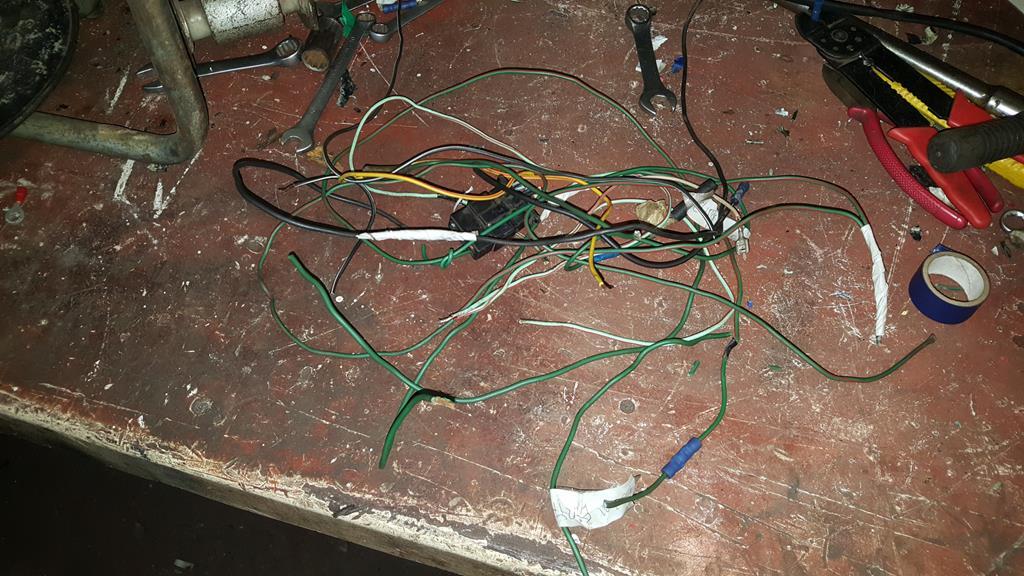 As I went along all the crimp connectors were removed and the joints soldered up before being wrapped in tape.. At least I know the loom won't pull apart now Battery end of things. 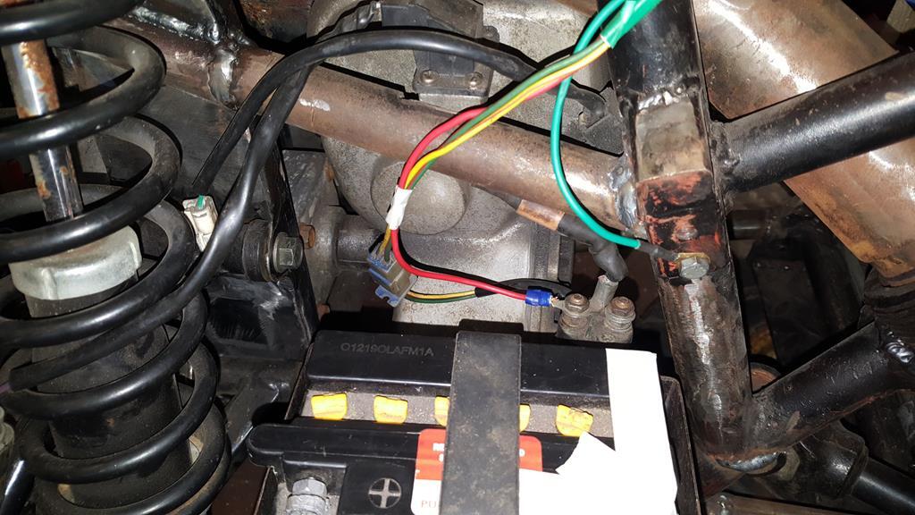 This bit of the loom was a massive mess with lots of crimp connectors! It looks way better now 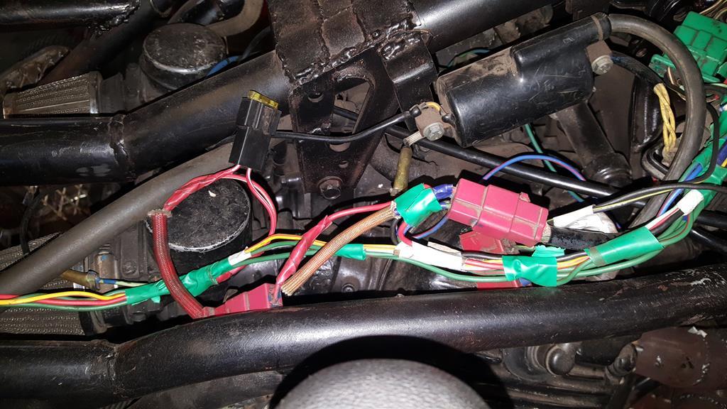 The front end splits nicely into two, it will split nicely into three when the headlamp is wired in. 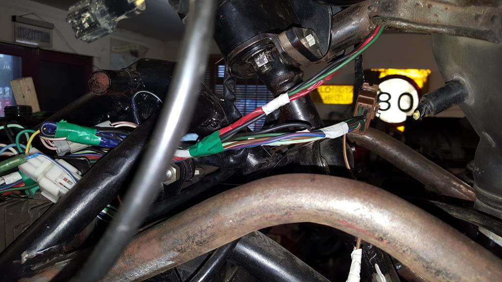 Speaking of the headlamp, these "not yet connected" wires go to the Quadzilla switch gear and are the very wires that give life to the lighting circuit. And the horn 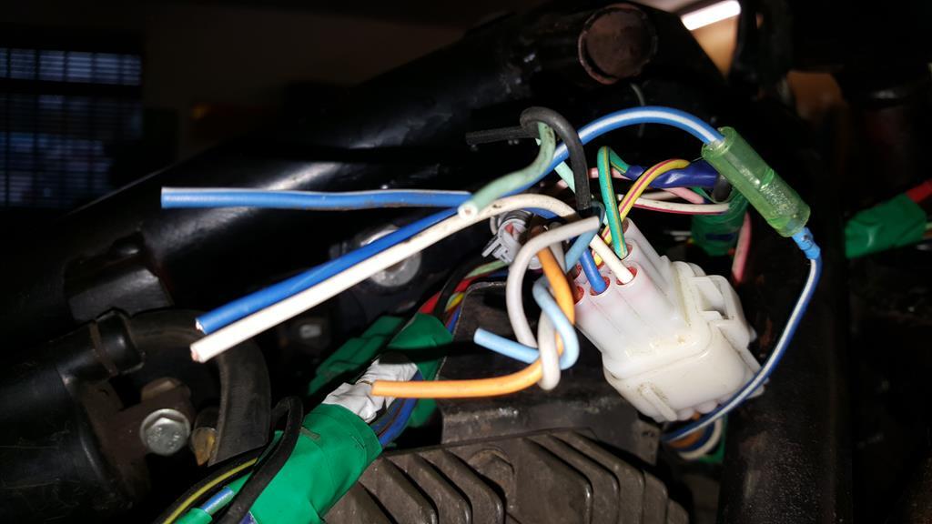 A day was spent turning this mess....  Into this non mess...... A day well spent 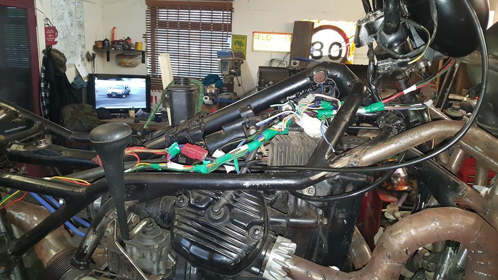 Having already mounted the voltage regulator the wrong way ie bolted directly to the frame, I needed to find a good way of rubber mounting it.. Which is where the random bit of Quadzilla comes into play as it has a few holes already with rubber isolating mounts in it... Just not quite in the right places..... 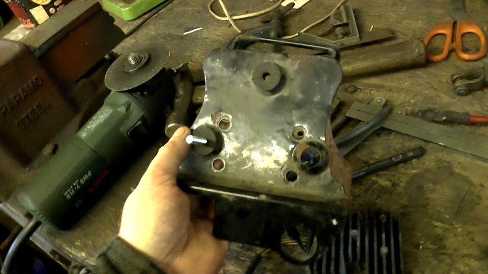 Soooooo.... Chop of the unwanted bits. 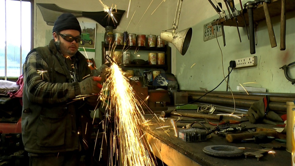 Slice 4mm from the middle. 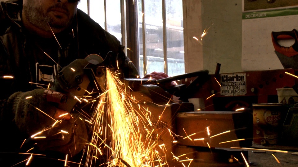 Weld the two halfs back together. 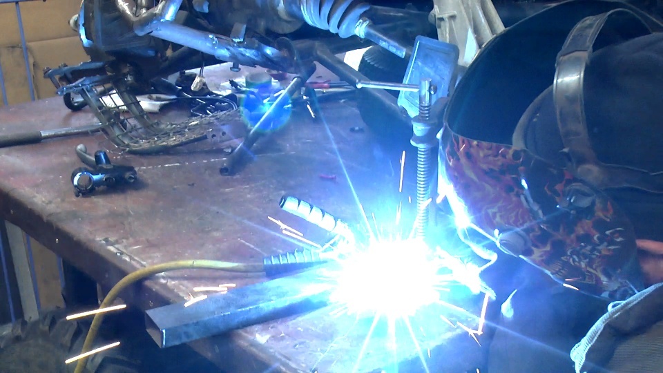 That should be strong enough 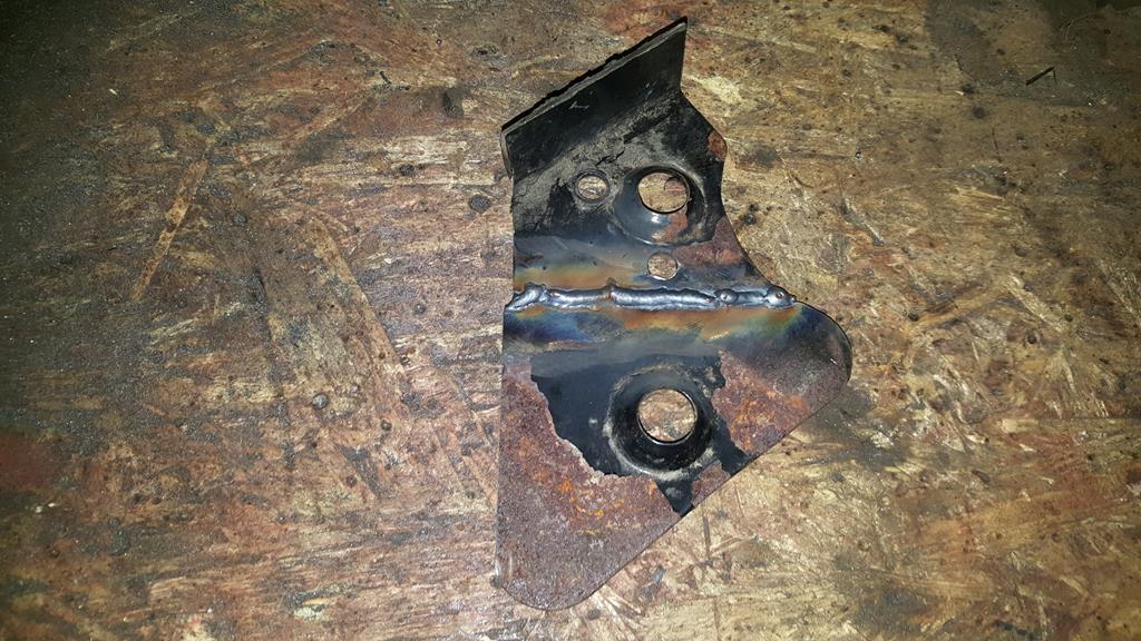 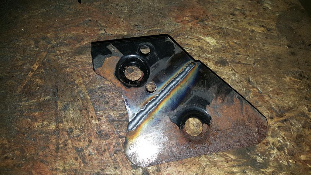 Drill a hole. 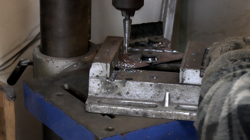 Bash the bend flat. 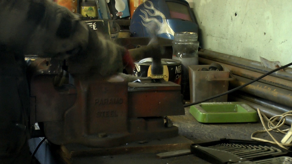 Drill a second hole then test fit. 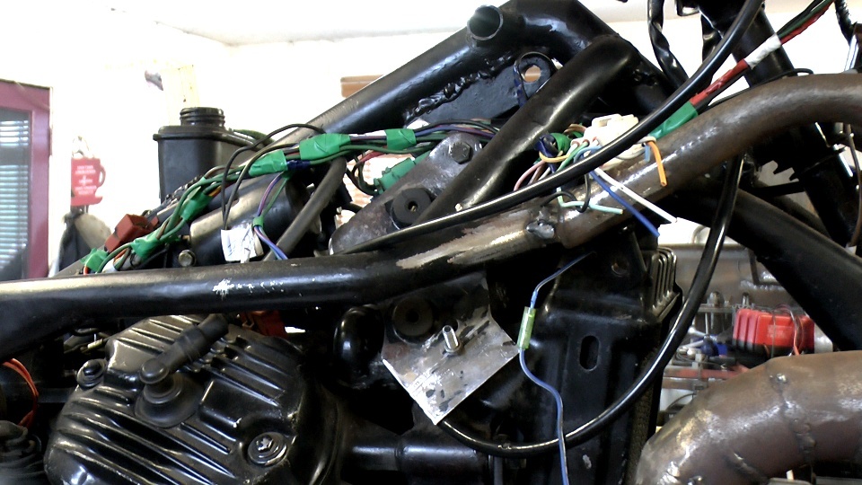 Cut and grind the bracket to shape. 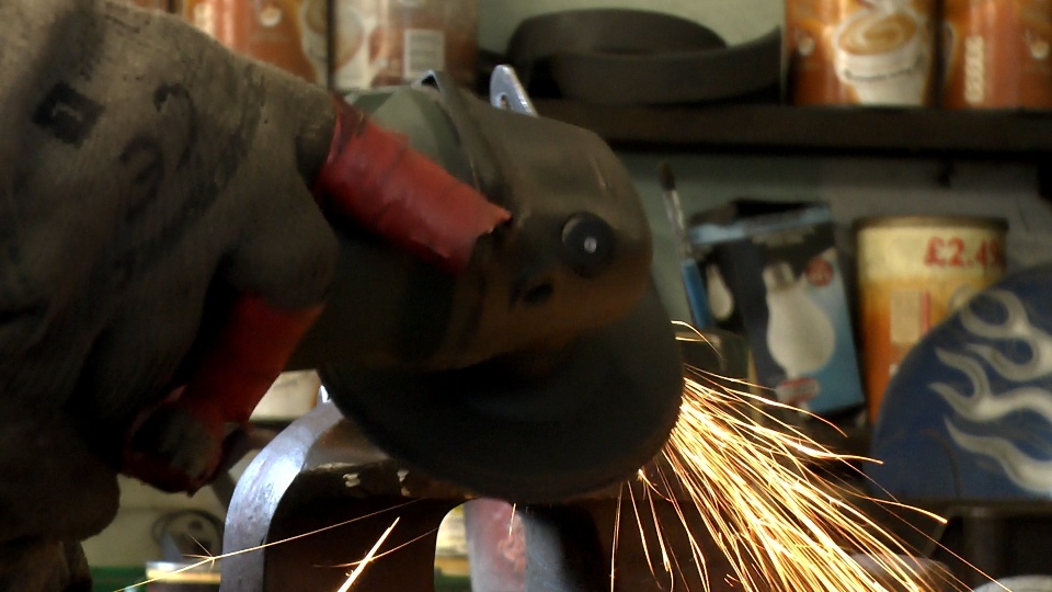 Bolt the regulator back on to the bracket.  Bolt the whole thing back on to MadTrax, plug the wires in.... Job done 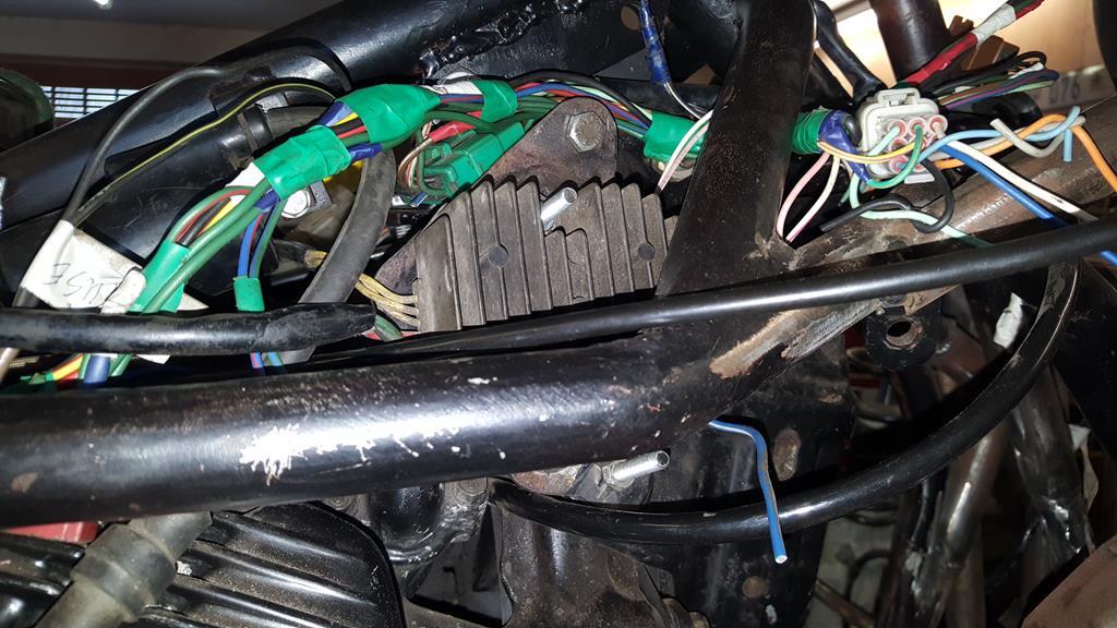 Whilst looking through the Quadzilla wiring loom for plugs and sockets I could use to wire in the front diff, I noticed something that would be a good and sensible upgrade to MadTrax's wiring.. A small bracket later. 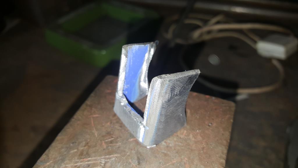 Which fits under the seat.. Or will do when the seat is on 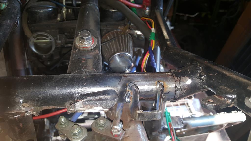 And I have a modern fuse box installed. 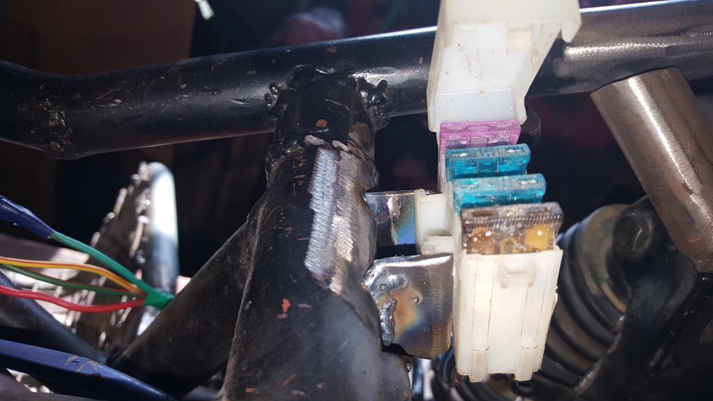 The next fun job will be working out how to fit a modern headlamp bulb in the back of this old army type lamp! 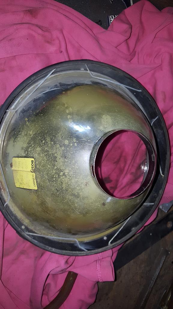 |
| |
My YouTube Channel www.youtube.com/user/UkWheelHorseBlokeQuote - D'you know, it's people like you, doing totally brilliant and pointless stuff like this that gives me a little hope for humanity |
|
|
|
|
Feb 25, 2018 11:31:34 GMT
|
With the wiring (mostly) sorted I couldn't tidy the loom up without knowing where all the wires would run to... All of which means I had to find somewhere to mount the battery! The only place for it to go was just infront of the rear R/S wheel (no pics as it's hard to hold a battery in place and take photo's at the same time), no ideal but it just would not fit anywhere else! I had already built a battery box, but hope to mount it??? This TB mount looks a good start 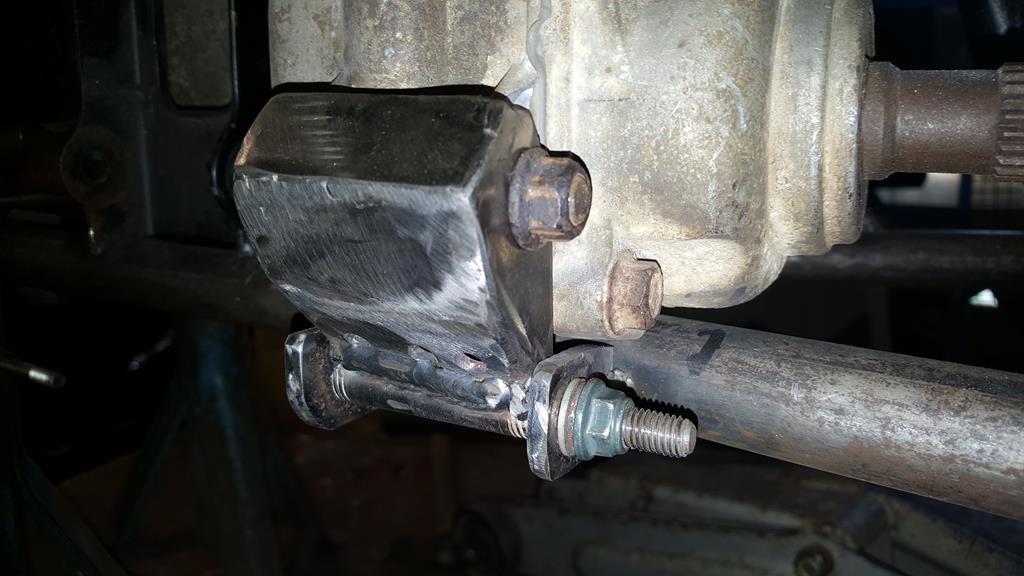 Lot's of chopping and welding later it looked like this. 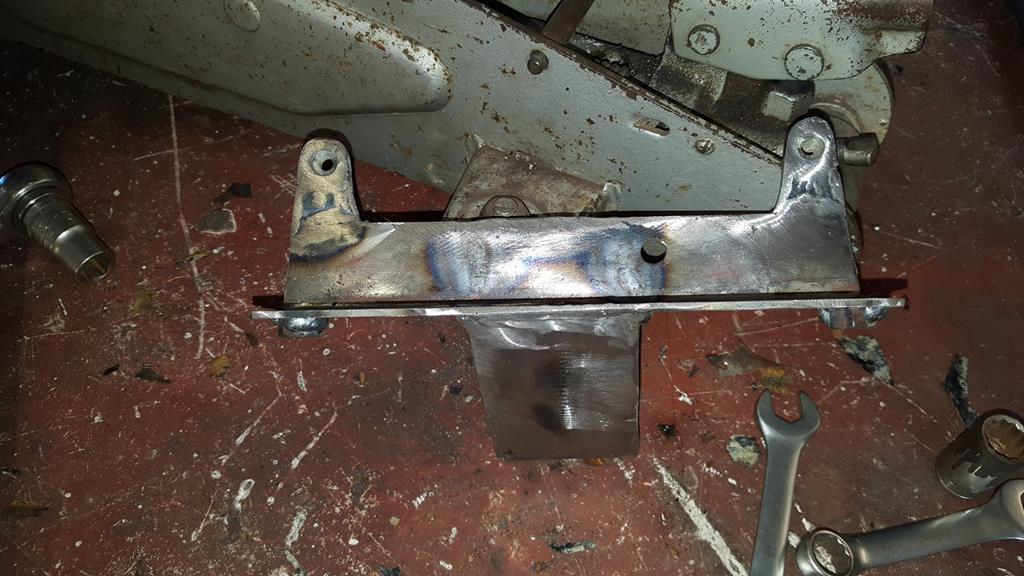 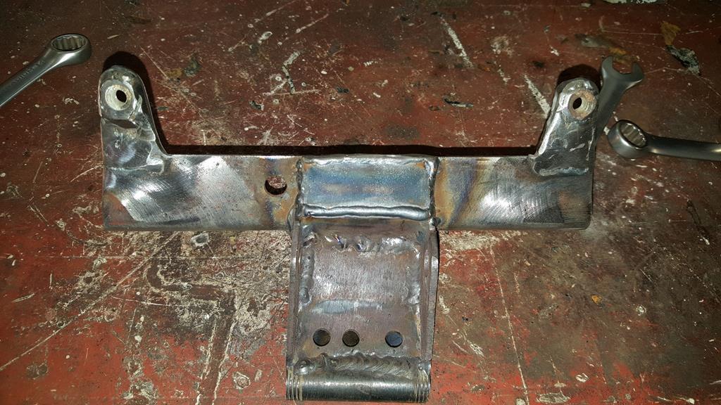 Checking the battery box fits.. 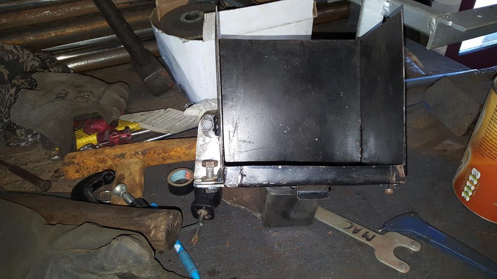 TB/Batt mount bolted back on to MadTrax 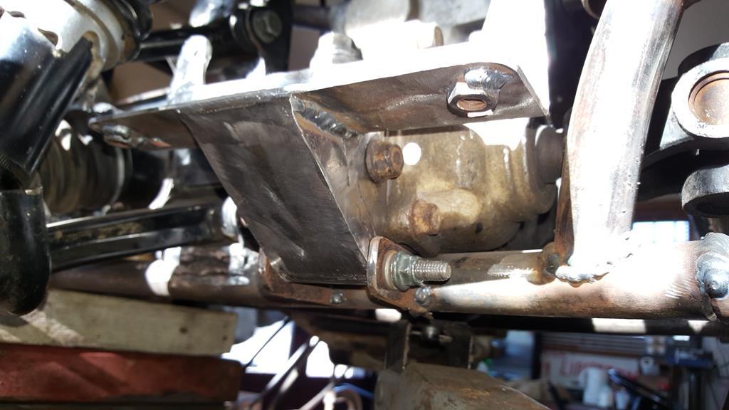 Battery plonked in place.. It feels nice and strong with no movement and will hold the battery in place no problem 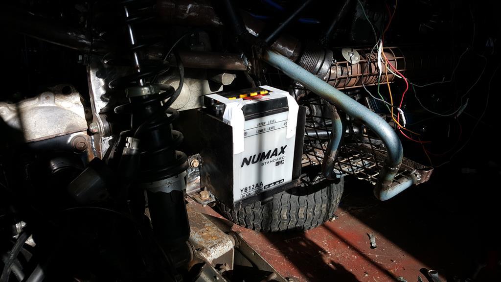 |
| |
My YouTube Channel www.youtube.com/user/UkWheelHorseBlokeQuote - D'you know, it's people like you, doing totally brilliant and pointless stuff like this that gives me a little hope for humanity |
|
|
|
|
Feb 25, 2018 11:27:05 GMT
|
Morning all, it's that update time again.. Although the wiring was operational enough to get the engine running, for some reason I just could not get the two warning lights on temp guage to work... These three! 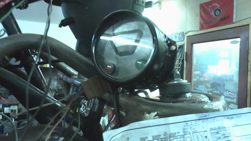 The one place where the lights/temp guage connect wiring wise is the voltage regulator which should (or so I thought) power the lights etc.. Now I will admit to to getting the power leads to the battery around the wrong way once, that coupled with finding out the regulator should be rubber mounted to the frame (so it doesn't earth through the frame) rather than bolted directly to the frame as I had done once!  So... Everything pointed to a fried regulator being the problem, a replacement with correct mounting bracket with the rubber bits was ordered.. 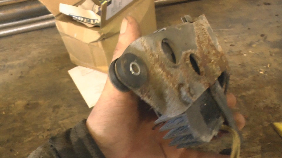 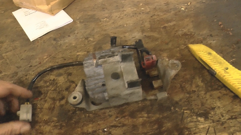 The result??? No Change!  The problem is this black wire from the regulator, there should be power in it but it was missing! 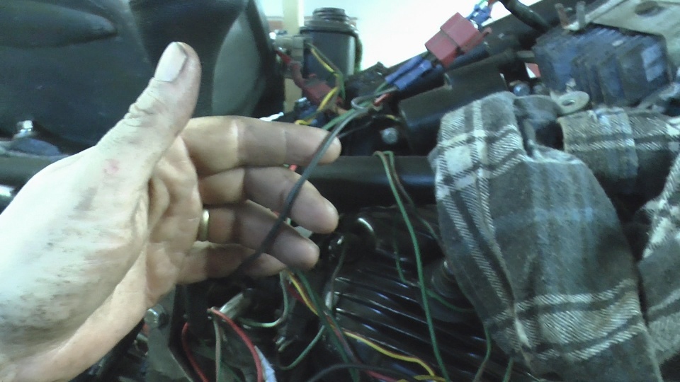 Time for a coffee and a bit of research on the internet to find out exactly what the blasted black wire does.. As it turned out it's the wire the regulator uses to keep a check on the voltage and should be connected to a live.. At the front-ish of the loom is this connector that has been taped up as I thought it wasn't needed... Yes it's the other end of the black wire and it should of been connected to a live feed form the ignition switch! "Bangs head and has one of those Doooohhhhhh moments"! 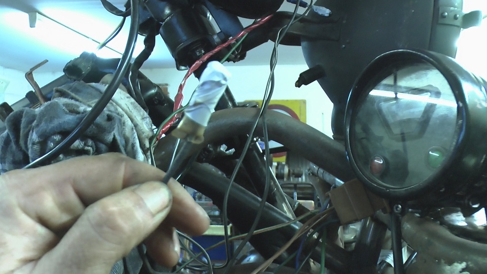 With that black wire connected to a live this was the result I know that in the grand scheme of things a couple of warning lights isn't a big deal, but it was really bugging me as to why they were not working! 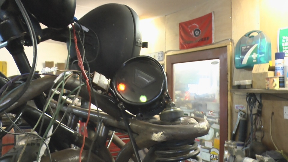 |
| |
My YouTube Channel www.youtube.com/user/UkWheelHorseBlokeQuote - D'you know, it's people like you, doing totally brilliant and pointless stuff like this that gives me a little hope for humanity |
|
|
|
|
Feb 10, 2018 12:25:22 GMT
|
We all have a "must build" project in mind, and this is mine.. Over the years I have restored WH's Built things that go on them such as a snowplow and harrow... Added a couple of extra wheels - The 6x6.. And even made a fast fun machine - Project Why Not.. Wheel-Vo is the silly/stupid one The other week I made a trip down to the south coast and came back with a car load of Wheel Horse.. A WH 312-8 although with no engine and trans it's more like a 300-0 Here it is back in the workshop thrown in a rather neat pile 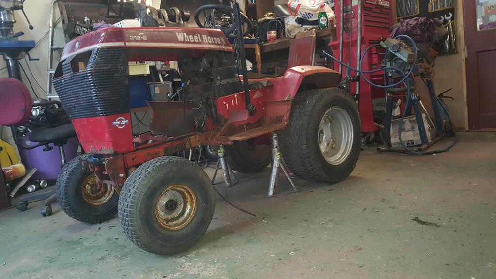 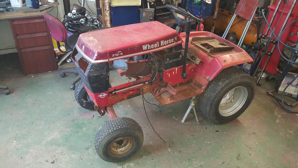   The plan? The title should of given you a clue, I'm on the look-out for a cheap Volvo that will give up a 2.3 turbo engine, gearbox, rear axle and maybe a few other parts, then sell on the rest to get a few £££'s back.. Of course a standard WH chassis won't be suitable so I'm going to have to build one, currently thinking of a full tube chassis, partly for the challenge as I've never built one before.. Having picked up a large amount of thick wall tube may have something to do with it Parts collected so far... A fuel pump and regulator, actually bought for Project Why Not and never used.. Also this narrow steering rack.. I can't remember what it came from, just it was a micro car of some sort. 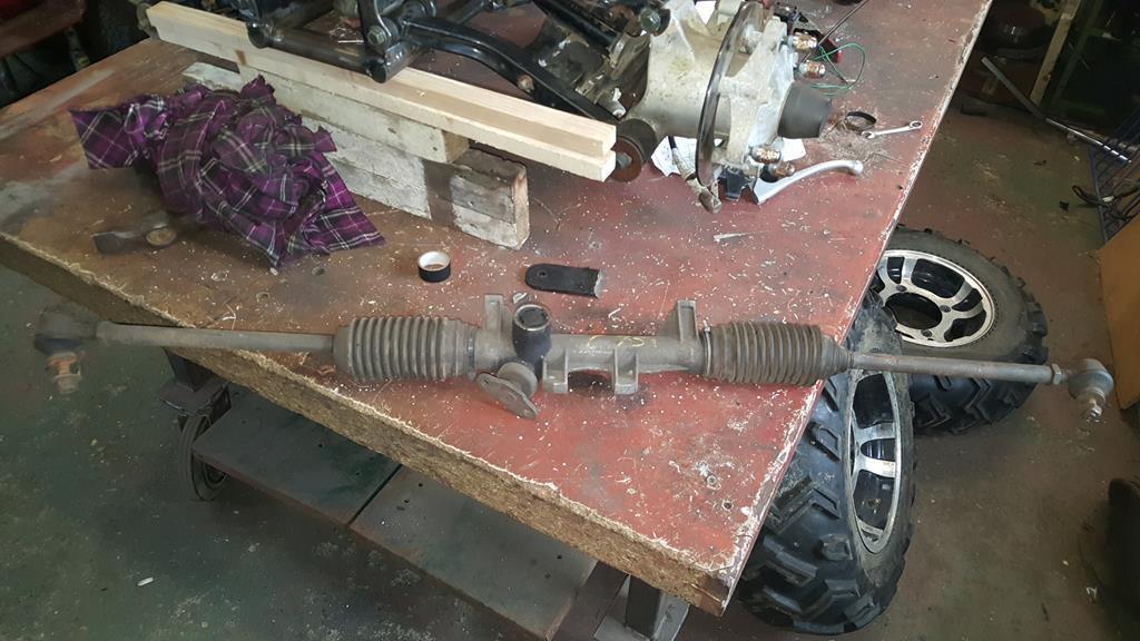 A lot of work ahead but I can/am collect parts while I'm finishing Project MadTrax.. Not much will be happening for a while as always this wil be a budget build and I need to raise the funds to buy a Volvo to give up engine,trans etc.. Oh... If your wondering why Volvo.... It's the sound and maybe watching too many Volvo drifting videos |
| |
Last Edit: Sept 17, 2019 15:12:21 GMT by Stigian
My YouTube Channel www.youtube.com/user/UkWheelHorseBlokeQuote - D'you know, it's people like you, doing totally brilliant and pointless stuff like this that gives me a little hope for humanity |
|
|
|
|
|
|
Time to sort the steering.. The problem I had was the Quadzilla steering column didn't fit the mount on the frame, and the gauge pods I made would not bolt on! But I still needed the bottom of the column as it does the steering bit! So I needed the Honda top half and the Quadzilla bottom half, of course they are not the same diameter and one would not slide into the other! A little bit of lathe work later had the solution to joining the coulnms together and keep them straight..  A close up.  To make sure nothing would move lot's of holes were drilled so I could plug weld through to the adaptor thingy..  My Murex Mig welded won't go all the way up to "Spinal Tap", so I turned it up a notch to 6 and zapped the parts together.. 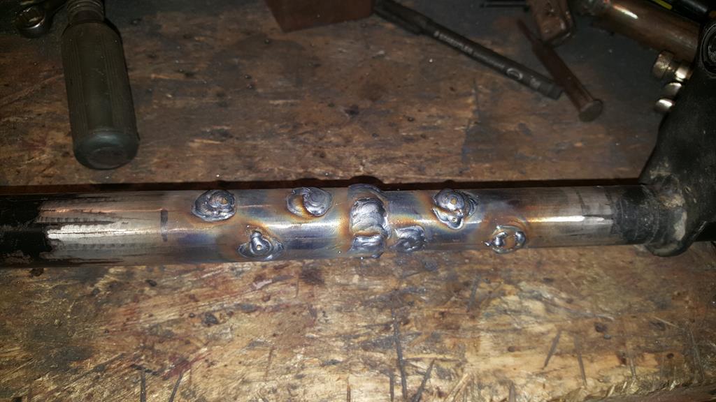 Cleaned up.. 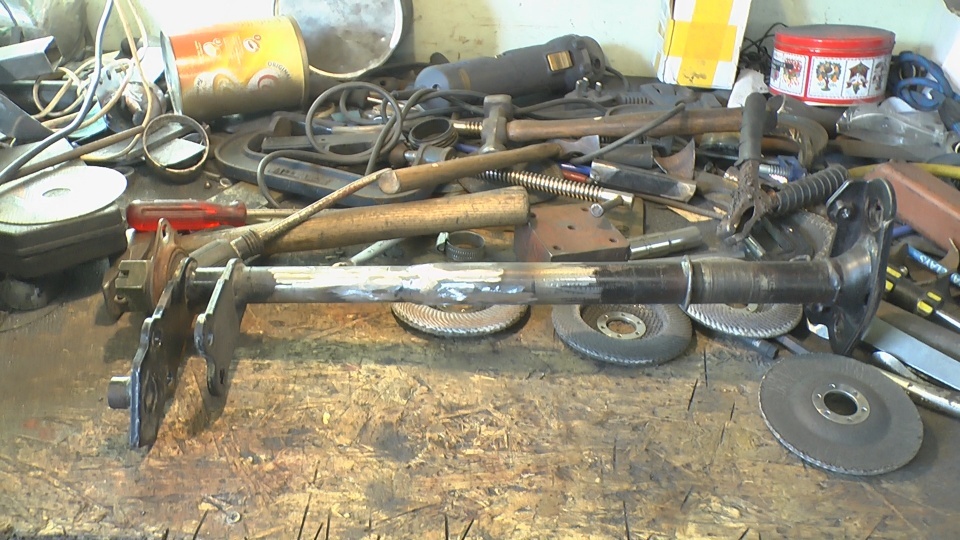 The good news is the column ended up exactly the right length, straight and the top and bottom halfs lined up, so it was bolted back in.. To celebrate the light and gauges were also bolted on. 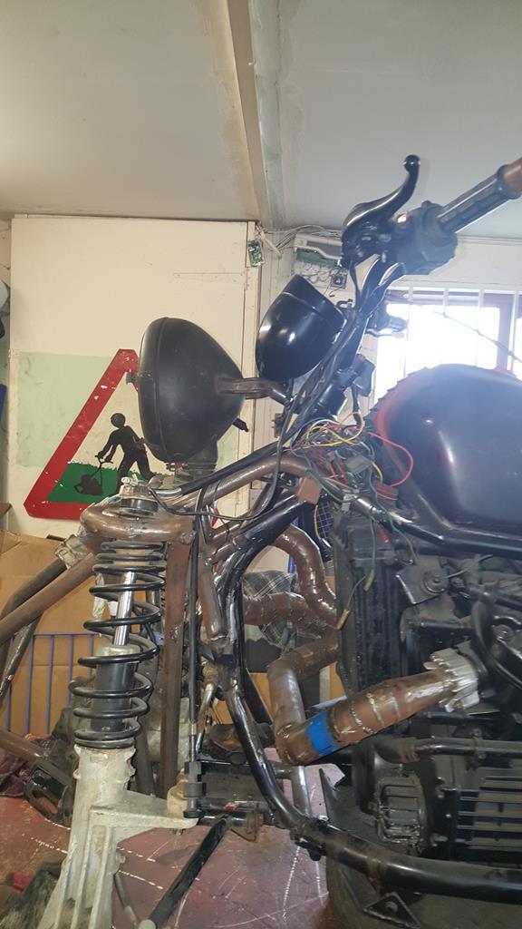 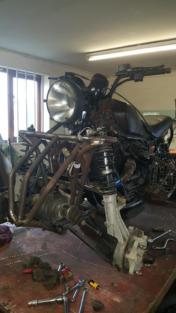  MadTrax looks kinda strange with no wheels, tank or seat on! 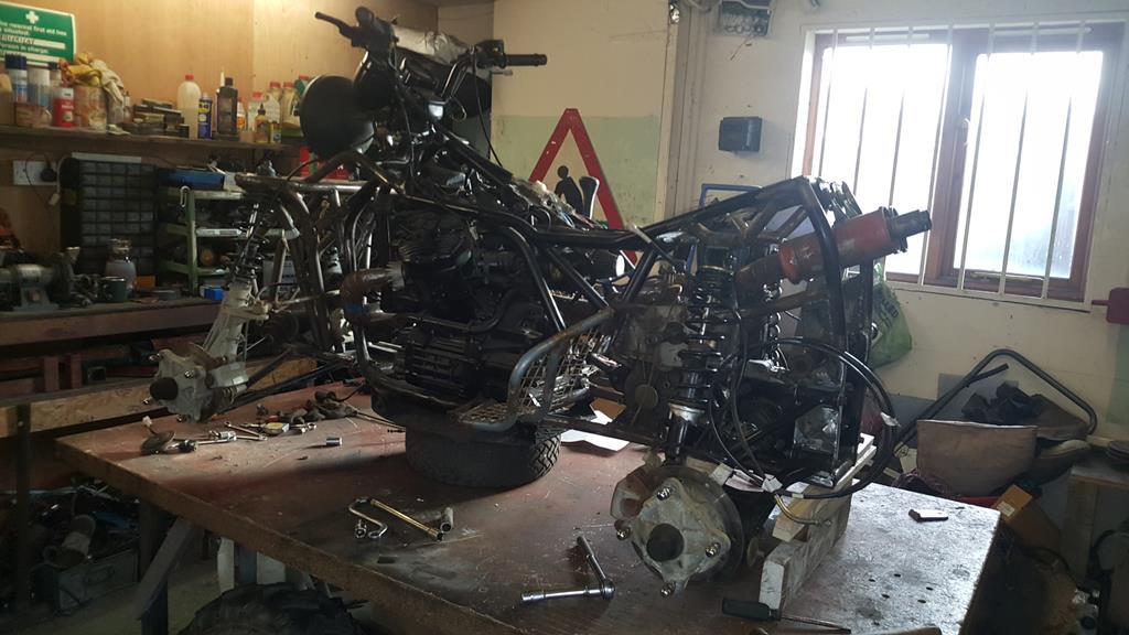 Now onto something fun, or not.. Wiring!!! I had already removed anything not needed from the Honda CX loom, but I also needed to splice in some of the Quadzilla loom! 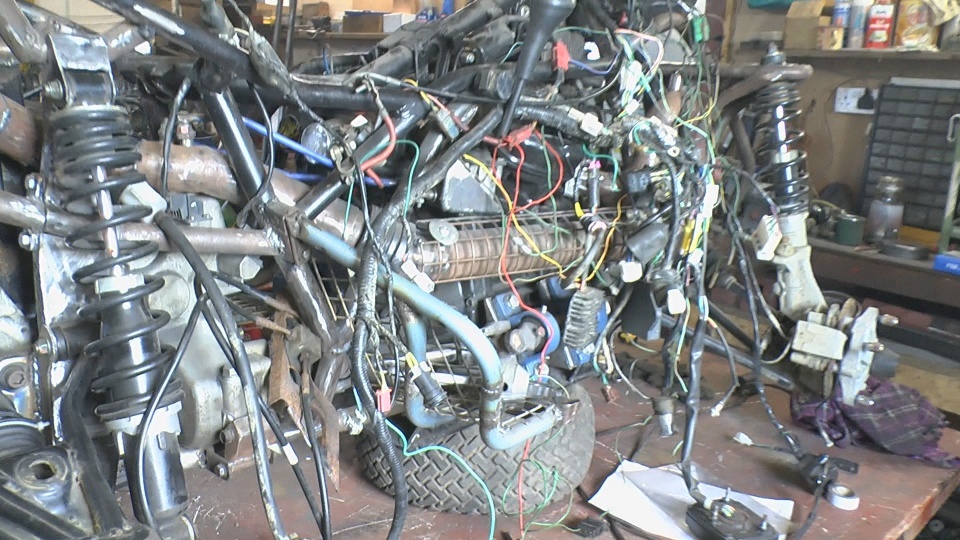 With the Quadzilla loom trimmed back to what I actually need things didn't look that scary!  To finish off thus update, a couple of videos.. Part 18 covers the above stuff, and in part 19 I get to start MadTrax for the first time |
| |
My YouTube Channel www.youtube.com/user/UkWheelHorseBlokeQuote - D'you know, it's people like you, doing totally brilliant and pointless stuff like this that gives me a little hope for humanity |
|
|
|
|
|
|
Now to try and get the rear end out.... Eeerrrr! 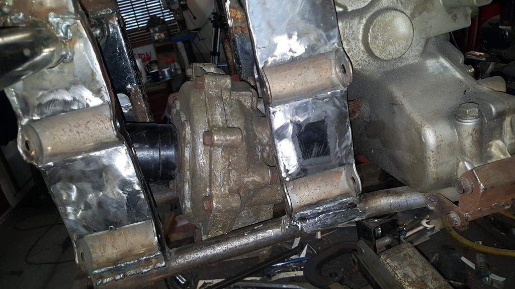 Ummmm! 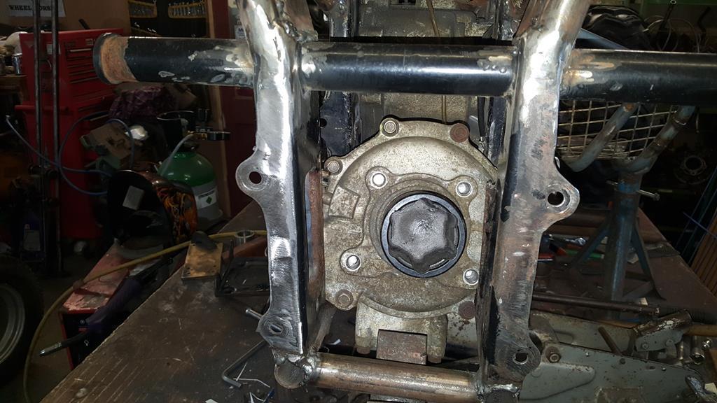 Until eventually I was left with this open space... 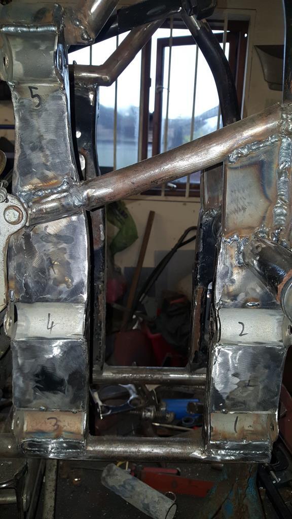 Which was only possible once I had cut this bit of tube out the frame... Another bit to make removable!  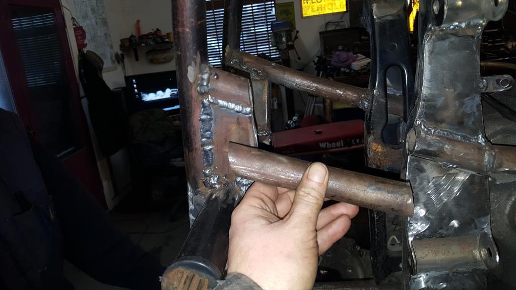 The rear end on the bench.. 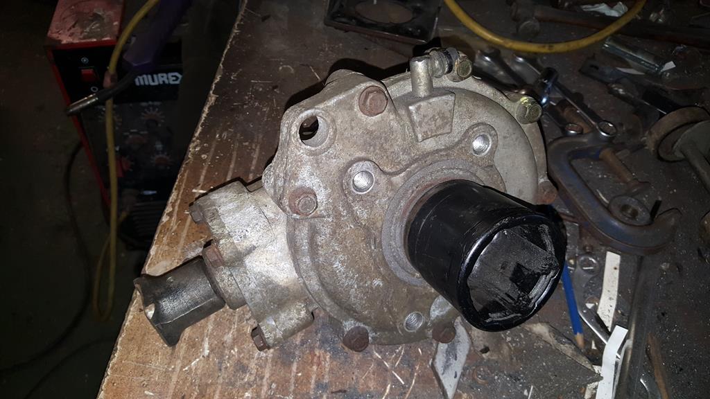 Rob picked up a wire brush and started to attack it to see what it would come up like. 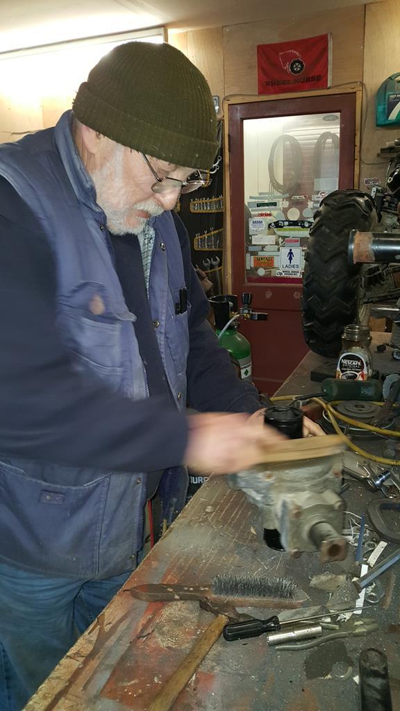 Not bad but I fear some mechanical cleaning help is needed..... Now where did I put those wire brush cup thingys that go in the drill??? 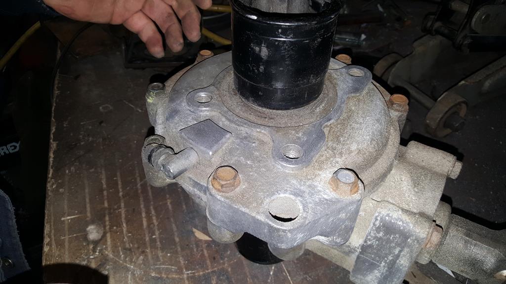 More metal work.. The removable bit needed to be made bolt-in-able, so some more metal was added.. 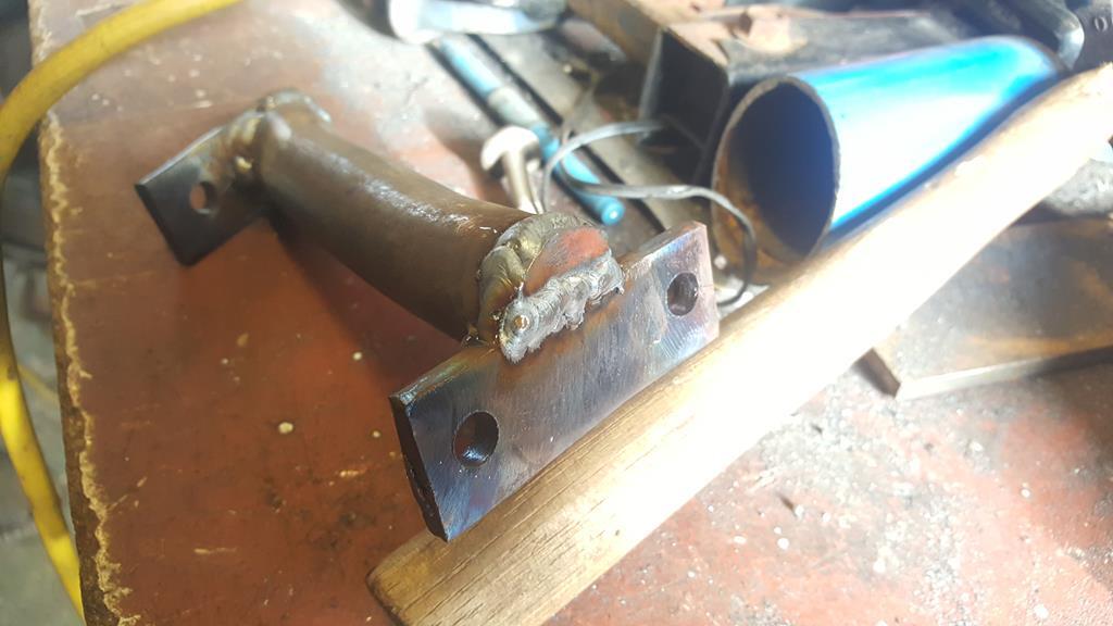 Some captive nuts would be handy to bolt it on, but I didn't fancy burning my fingers trying to hold the nuts in place while welding... So may I introduce to you all the sacrificial pencil  Not only does the pencil screw into the nut very nicely, any pencil that burns off is easily removed from the thread  Welded in with not a welding splat on the threads in sight Ok, this pic may be of the opposite side to the above pics, but it does point out the big hole in the end of the tube where it's been cut off.. 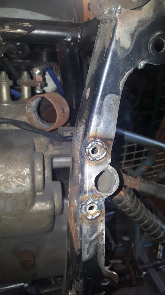 To fill the holes I found a couple of washers about the right, cleaned them up and clamped them onto a bit of brass plate. 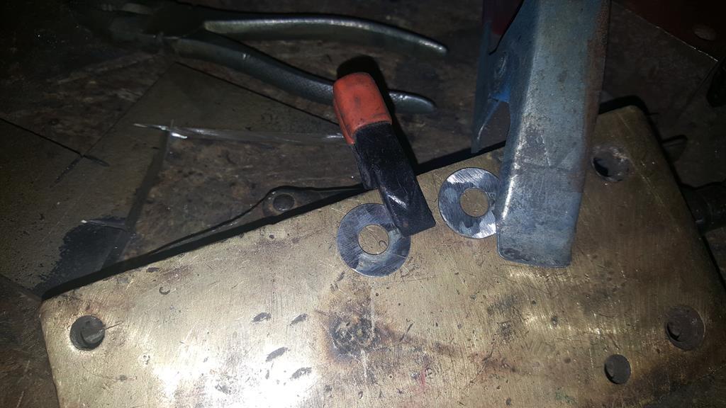 The holes in the washers were then welded up, the weld won't stick to brass.. Then a couple of "trimmings" were tacked on to give something to hold on to. 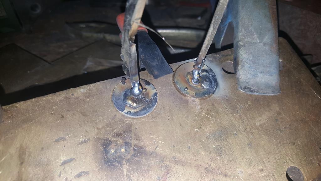 Once removed from the brass they looked like this.. 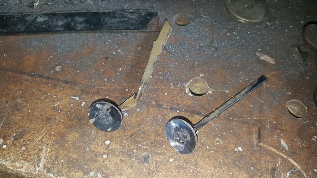 Washers welded in.. 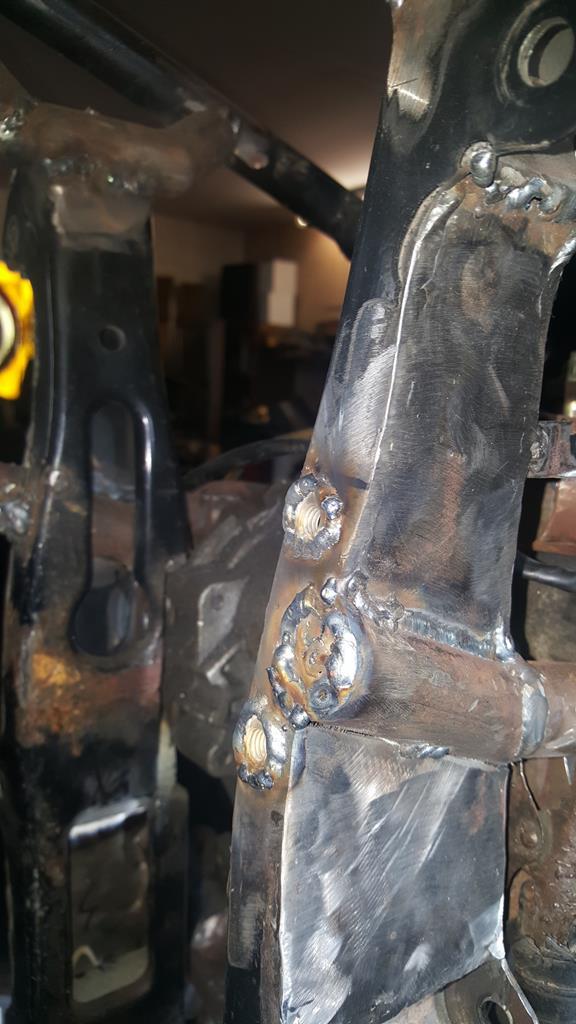 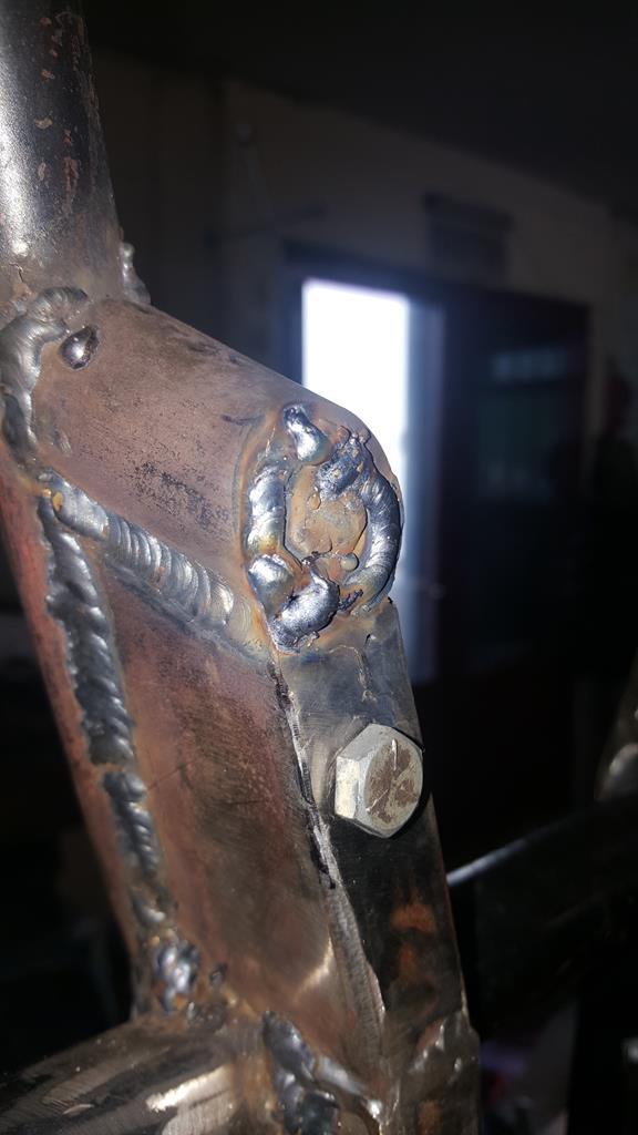 And once the welds had been cleaned back the removable bit was bolted back in.. 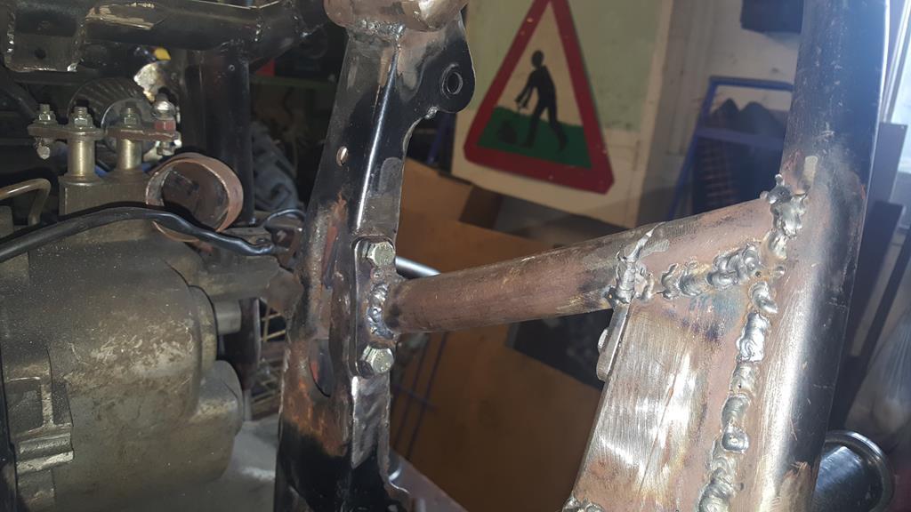 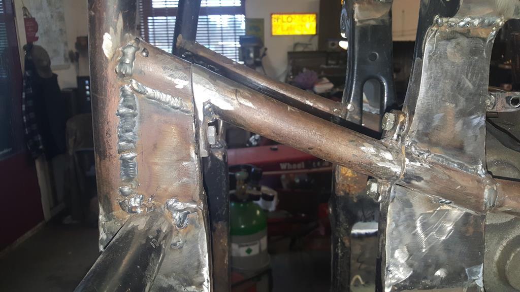 |
| |
My YouTube Channel www.youtube.com/user/UkWheelHorseBlokeQuote - D'you know, it's people like you, doing totally brilliant and pointless stuff like this that gives me a little hope for humanity |
|
|
|
|
|
|
It's definitely a thin line between bonkers and genius, but I think we'd all agree you're just the right side of the line! The right side of the line eh.. That's good to know as my Wife often wonders It's definitely a thin line between bonkers and genius, but I think we'd all agree you're just the right side of the line! Indeed. But only just! Only just is close enough for me That gear stick is just awesome!! It's not something I have seen done before, maybe it's because "I'm close to the line", that I'm even thinking of doing it... Then again, how many people have a hip joint to hand Quite a bit to report, I have made a good start on the left side with the suspension mount strengthening.. When I put the TB in I had to cut a bit of tube out, so back in it went..  A close up. The captive nut is for the TB side mount. 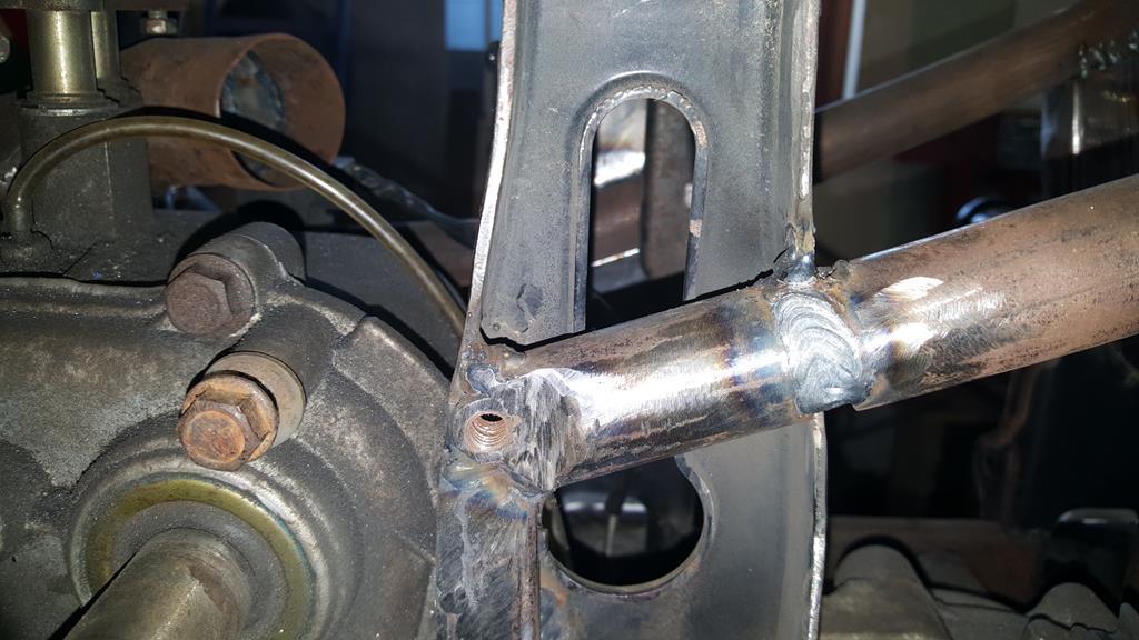 Only a couple of small plates to go in at the bottom and a lot of welds to grind down..  To try and keep things in order (must be a first) here's part 17 of the build. To finish off the strengthening on the left side I needed a couple of small plates to go at the bottom. Due to the small size of the holding them in place just wasn't going to work without setting fire to my fingers, so I welded a couple of small off-cuts to the plates to act as temporary handles. 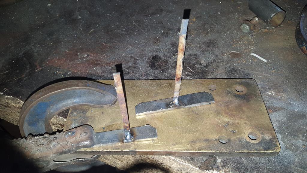 Plates tacked in place.. 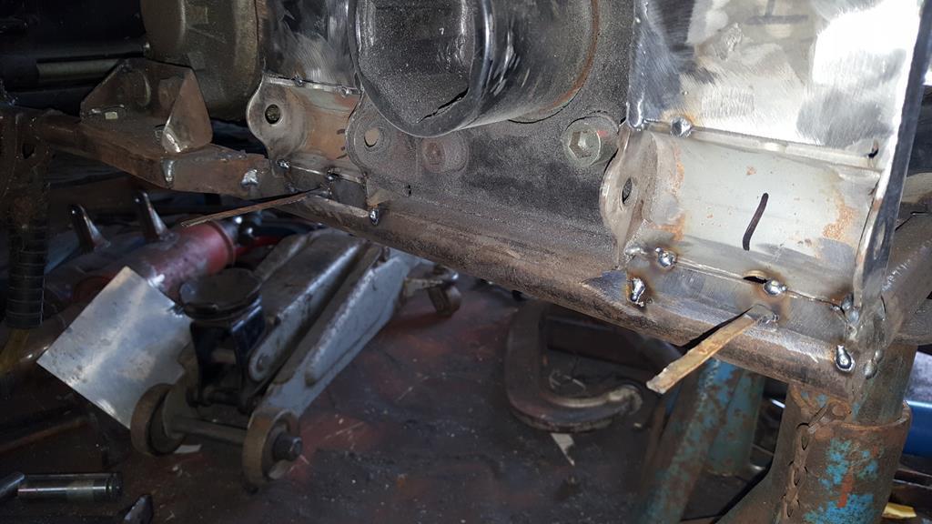 Once the plates had been fully welded on the time had come to tackle a job that thus so far had caused me lot's of head scratching.... Removing the rear diff/final drive thingy.. 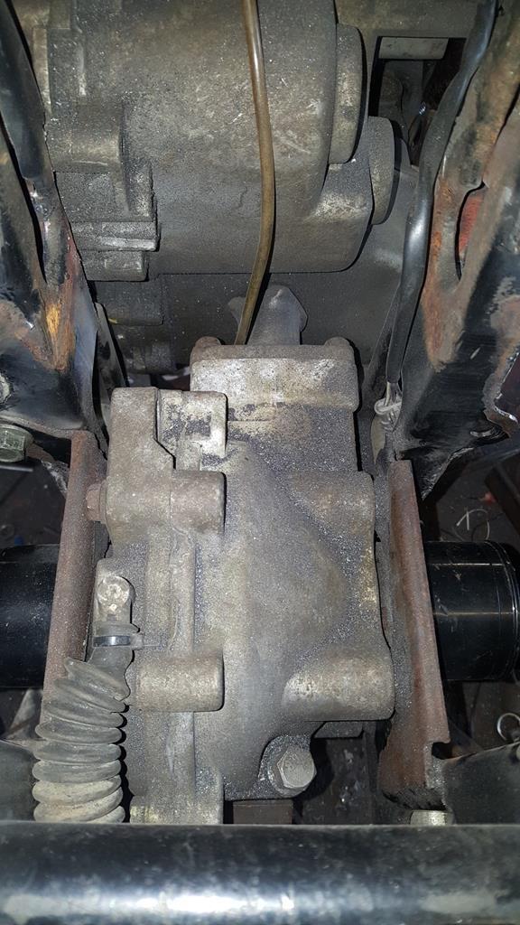 The right side already had a removable plate.. 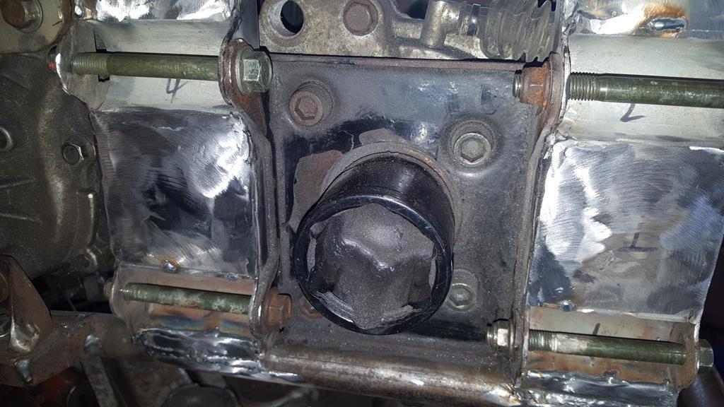 The left side didn't, but if I could make it removable them I might stand a chance of getting the rear end out.. HHmmm... Some nice welds to cut through! 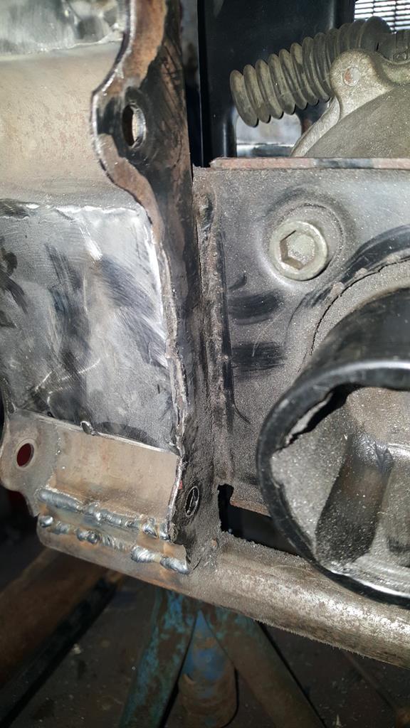 But before I started cutting metal a template was needed! 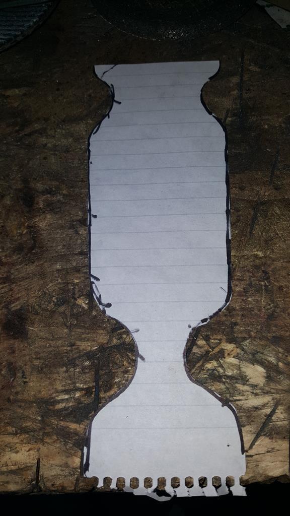 Ok, I needed the bit's marked F and R but the off-cut in the middle is a funky shape 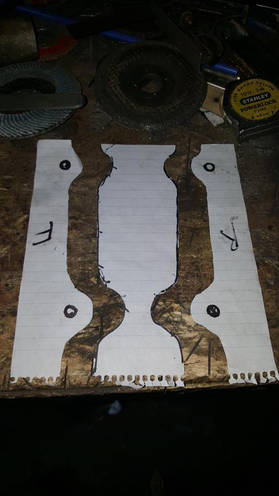 This was part of the Quadzilla front end.. Some cutting needed but it's just the right thickness for what I need. 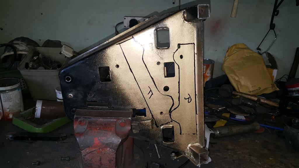 Here's the plate cut out of the frame and the extra couple of bit's of steel which will make the plate removable.. 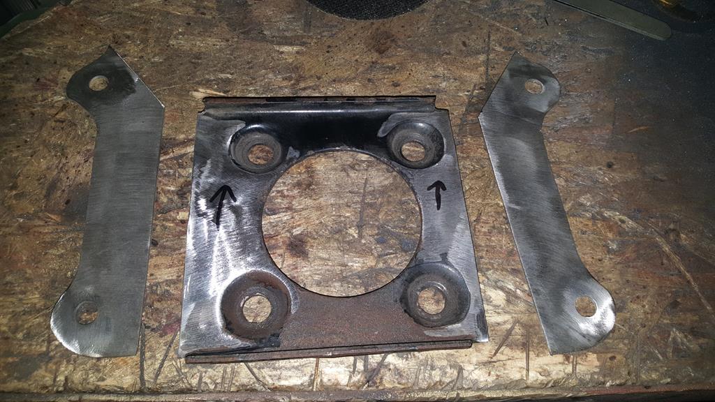 With all the parts bolted back on some tack welds were added. 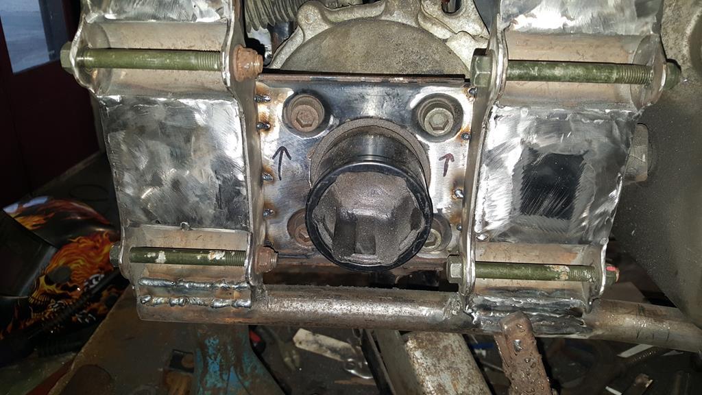 Back on the bench the now removable plate was clamped around some box and a bit of angle to hold it all square while I zapped the joins up.. Don't think it will be moving now 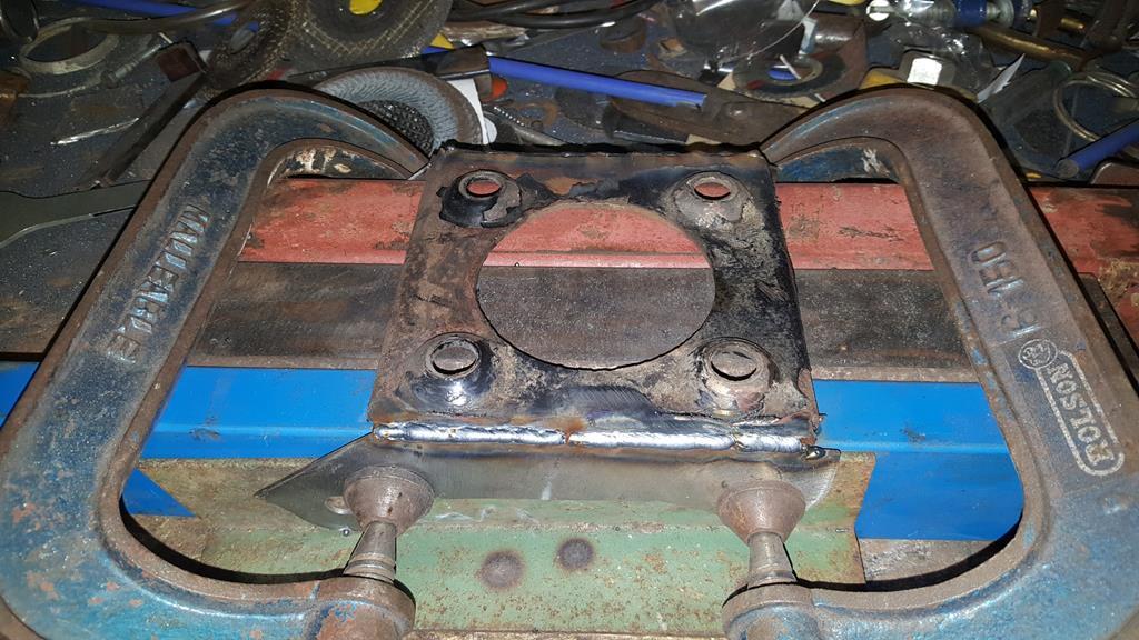 |
| |
My YouTube Channel www.youtube.com/user/UkWheelHorseBlokeQuote - D'you know, it's people like you, doing totally brilliant and pointless stuff like this that gives me a little hope for humanity |
|
|
|
|
Jan 17, 2018 21:20:09 GMT
|
Well, a bit stuck on the drive train at the mo.. The Honda Silverwing final drive/90 Deg thingy I was planning on using just won't work! I did the maths on sprocket sizes to work out the 5 - 1 ratios I would need and the big sprocket would need so many teeth that it would be nearly a meter diameter! Price wise it would be very much the wrong side of £1000 and the sprocket would be so big it would cut the quad in half! So.. some more thinking needed.. I need a strong 1 - 1 ratio 90 Deg drive that will fit in the rather small space available! Sooo... What to do next.... Some welding me thinks At the back where the new tubes meet the Quadzilla suspension mounts it looked ugly as I had just cut the tops of the mounting panel off.. A bit of cutting and welding later had a couple of bits of box welded in just above the anti-roll bar tube.. That looks better and stronger  Part of the plan has always been to box in the pressed steel suspension mountings as I hate the look of pressed steel, and they never looked strong enough anyway! Starting with one of these, a bit of tube with washers welded on both ends. 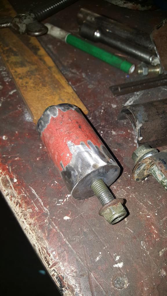 Which happens to be a perfect fit inside a thicker bit of tube that has been cut in half.. 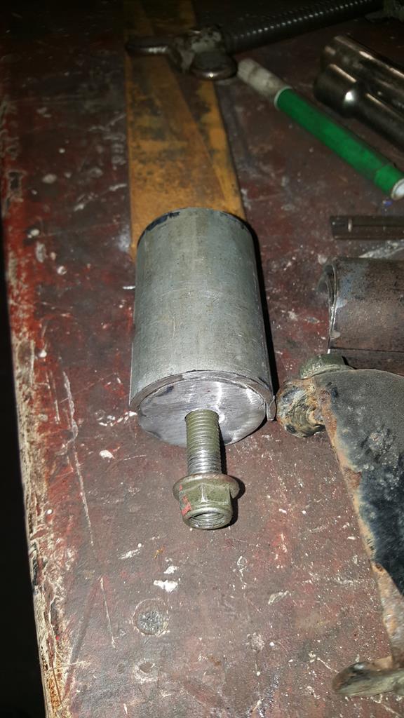 Bolt it to the suspension mounts and you have an ideal way of making sure all the bit's of half moon tube fit in the same places.. 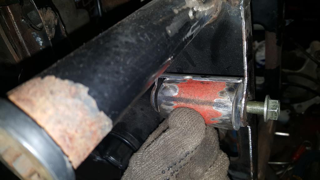 A bit of tack welding later.. 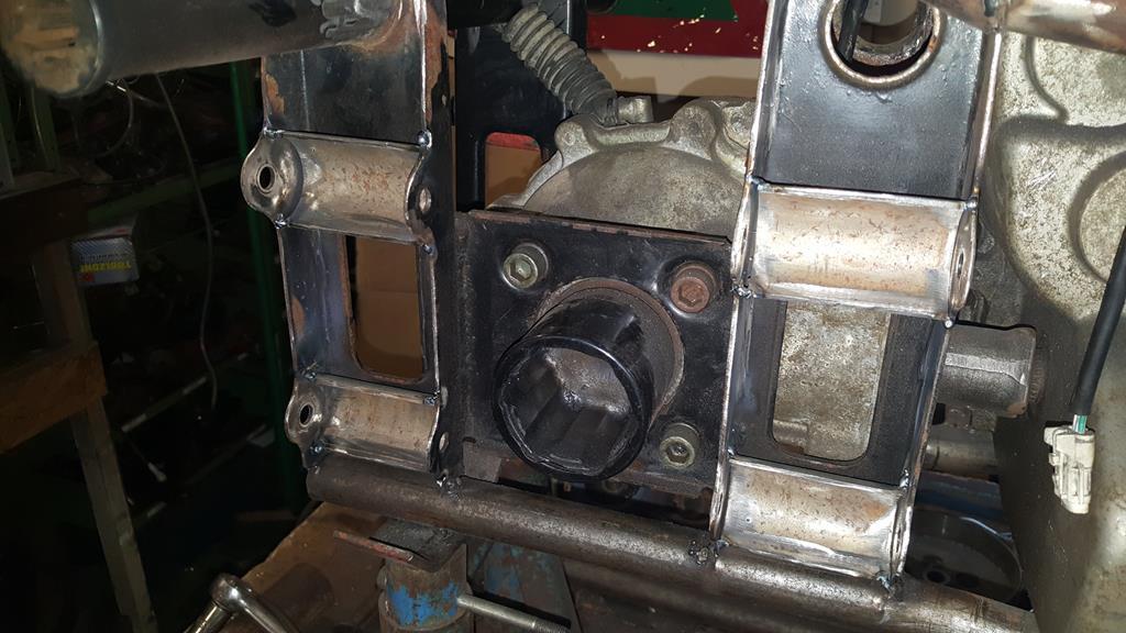 Best check for clearance, plenty of and more travel than will ever be needed 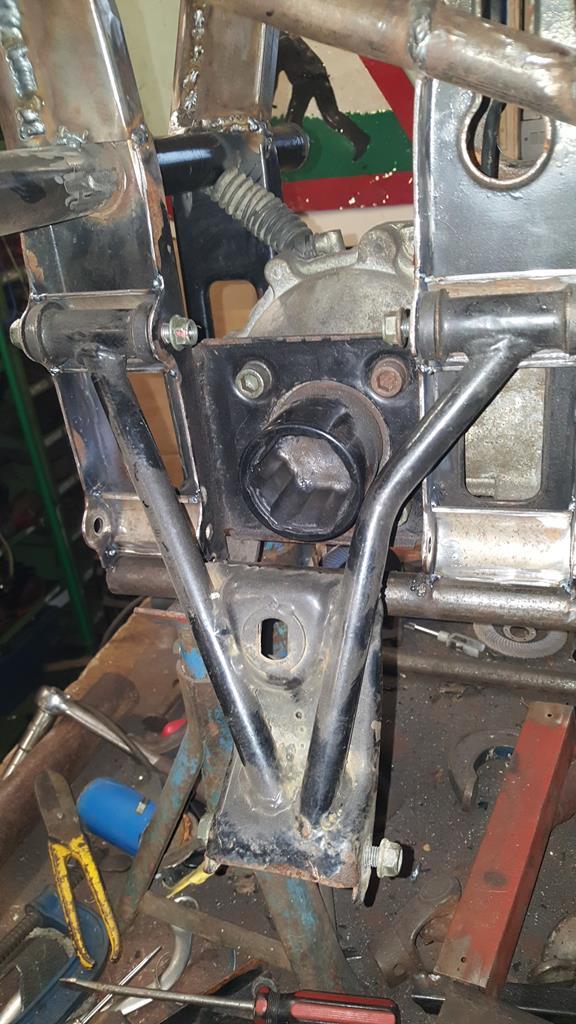 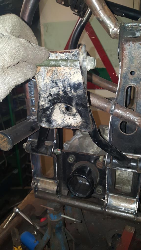 Now to fill the gaps, the top of this speaker stand is about the right thickness.  Four plates cut to size and tacked on plus a template for the next panel.. 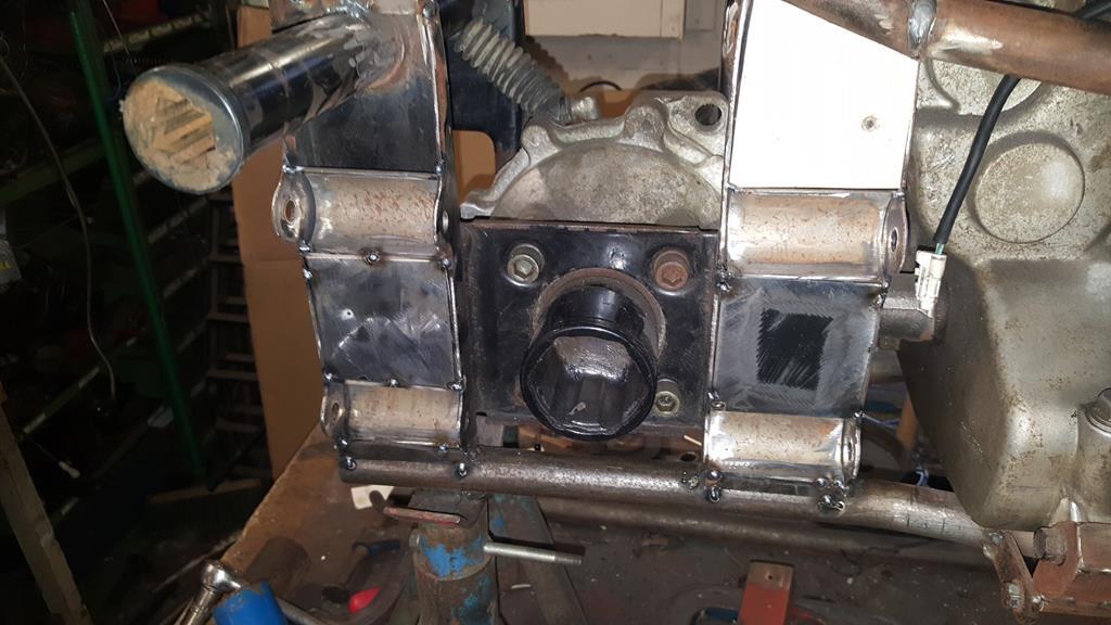 The right side almost done.. A few welds need a clean up, and a few of the welds won't be done until the frame is stripped and on it's side.. I hate welding upside down and I'm rubbish at it!   Best make a start on the other side, templates cut out..  And marked out on steel... It's a good job speaker stands come in pairs  |
| |
My YouTube Channel www.youtube.com/user/UkWheelHorseBlokeQuote - D'you know, it's people like you, doing totally brilliant and pointless stuff like this that gives me a little hope for humanity |
|
|
|
|
Jan 17, 2018 21:11:24 GMT
|
I needed a better looking bracket to mount the transfer box shifter stick as the Quadzilla one was too big and very ugly. I'm sure you can guess which one is the new one 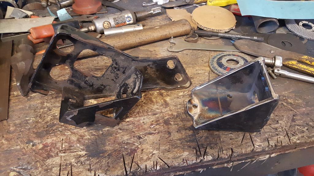 A view of the underside.  Shifter bolted in. 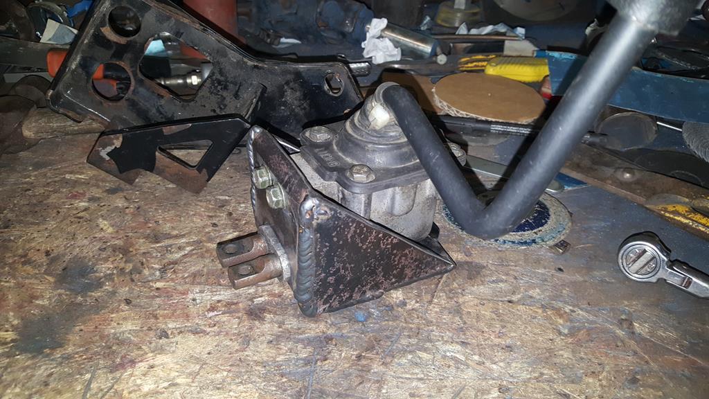 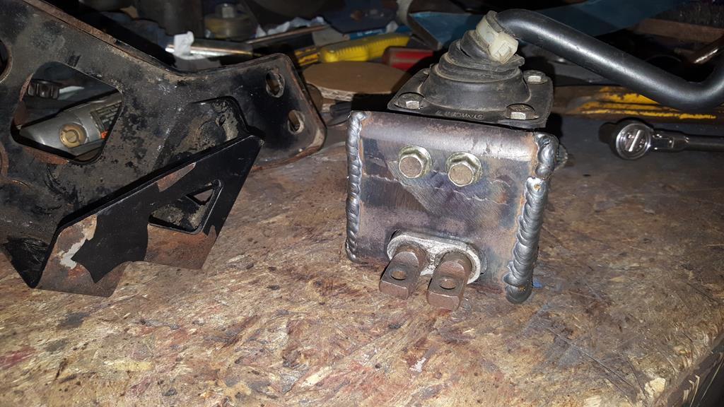 Still not quite sure where to mount it on the frame at this point, so I welded a couple of bolts to some blue steel bar. 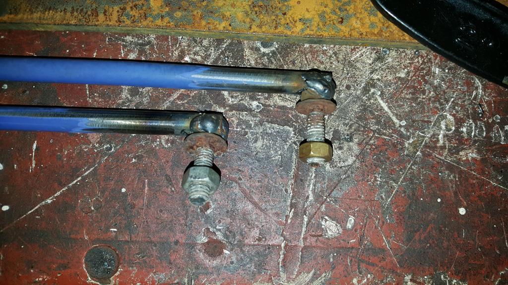 Very long bits of bar 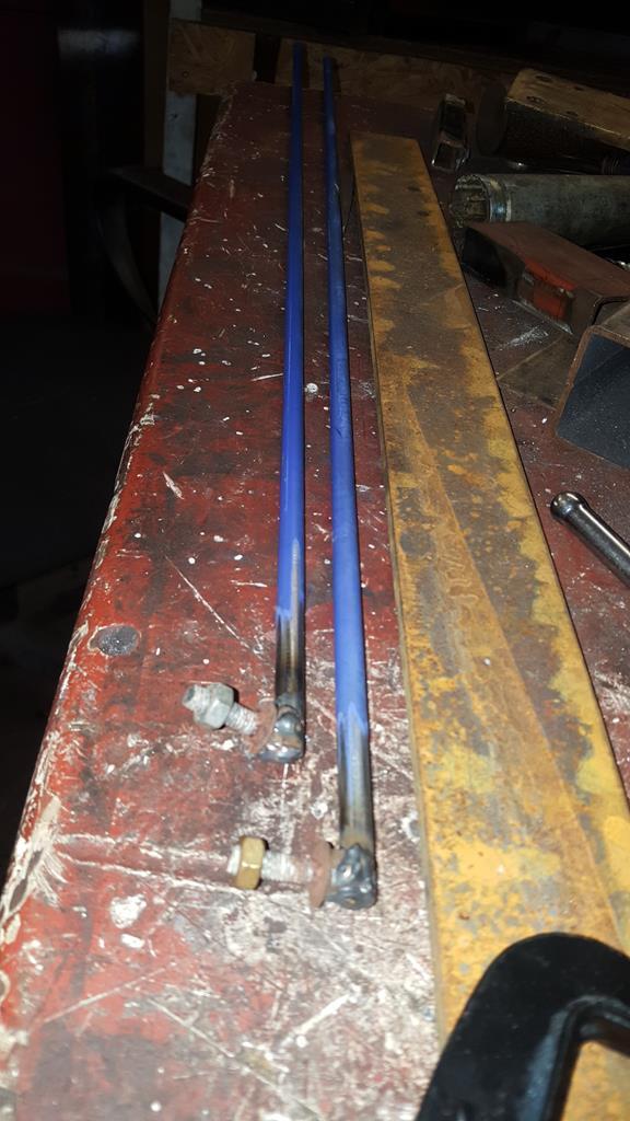 With the "bolt ends" of the rods stuffed through the frame and bolted on the TB levers, I could see there was a fairly straight run to connect the rods to a "next to tank" mounted shifter... But then I found out all the shifter marlarky fitted nice just above the exhaust, tucked into the frame a bit.. 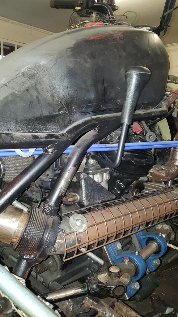 Just enough space to get the connecting rods on. 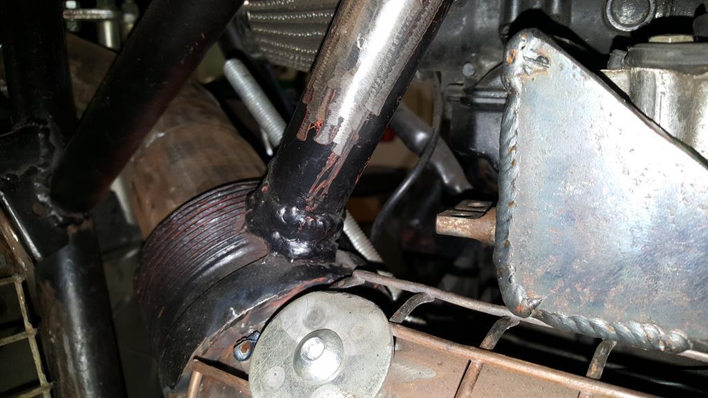 With one shifter box mount thingy done, the rods were shortened a bit, had a few bends put in and a bolt welded on the other ends.. It's a bit crude, I may re do the rods with rose joints, but for now the shifter works very well, and you get a reasuring "thunk" sound as the TB goes into gear 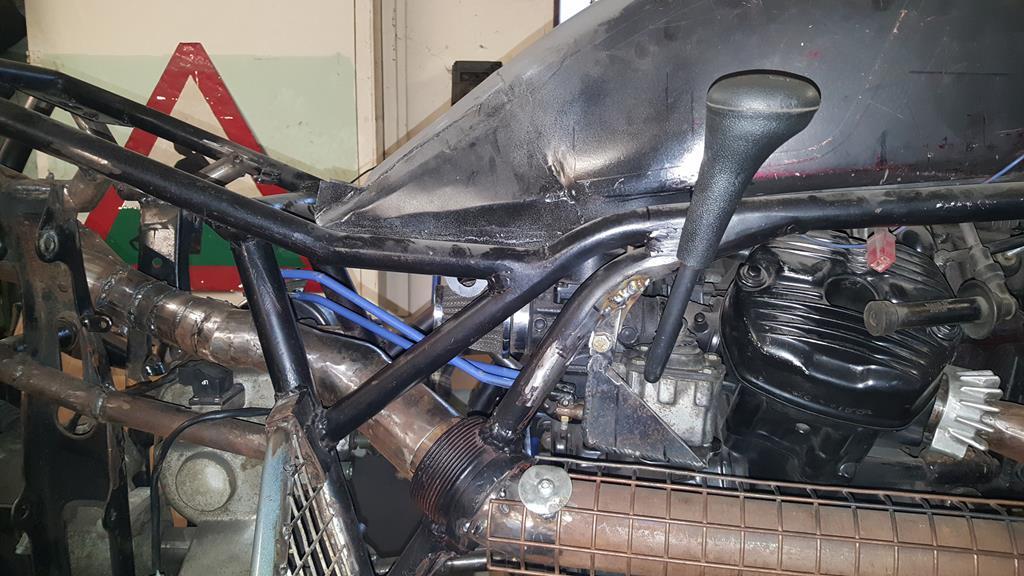 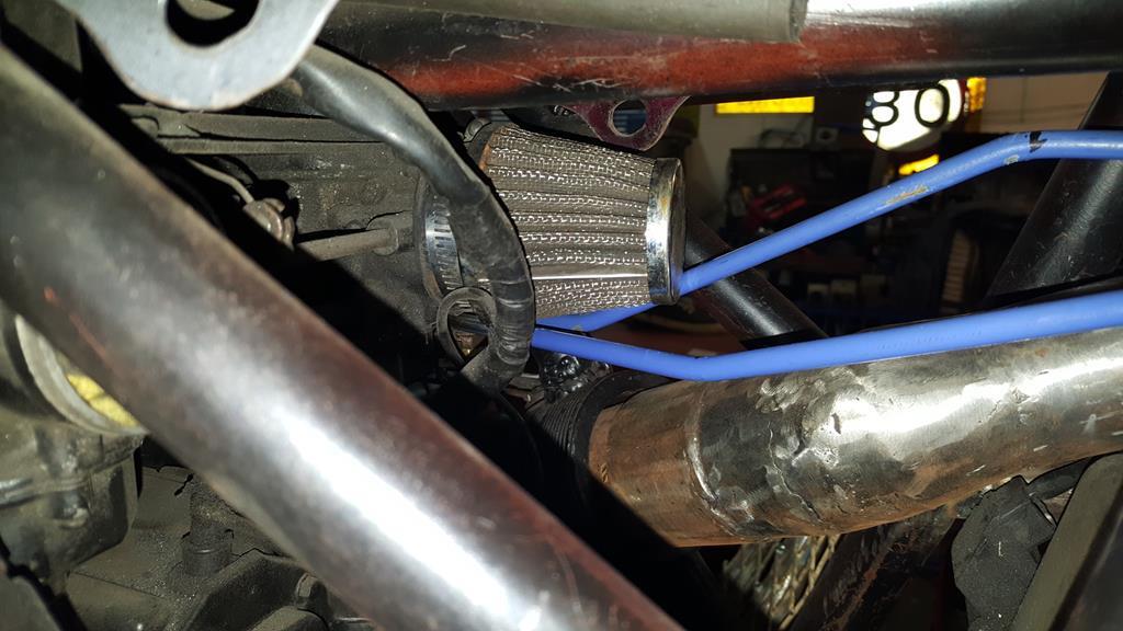 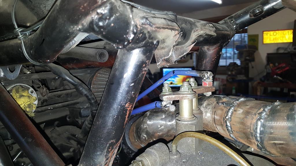 As you can see the shifter stick er... Sticks a fair way out from the gas tank.. A bit too far out for my liking..  Before I could narrow it I needed to find out why the stick just fell to one side under the weight of it's self. Once cracked open I found two springs were missing that that should hold the gear stick in the middle.. Not being able to find any compreession spring in the workshop that were the right length, width and strength I found a couple of bit of clear fuel pipe work just as well 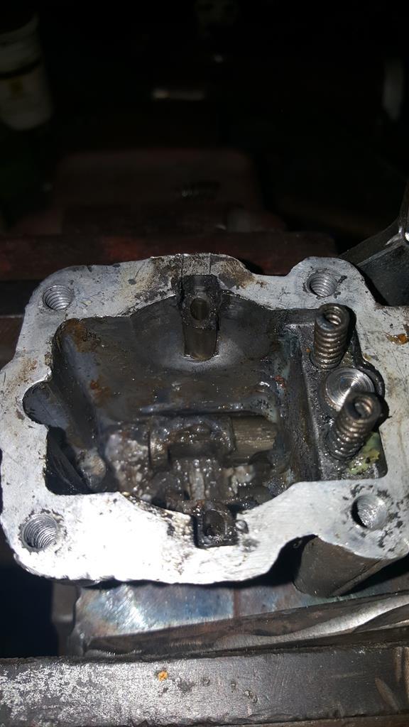 Just over an inch removed from the shifter.. Both halves were V'ed before welding back together to give maximun strength.. It looked quite nice once the welds were ground down nice and smooth 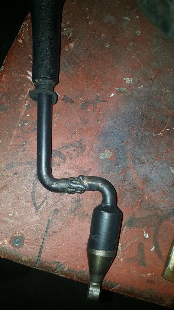 Bolted back on to the frame, but I don't like the look of the shifter knob, it's more "Montego/Maestro" than MadMax, but thanks to Nigel I have something a bit er... Different to graft on... 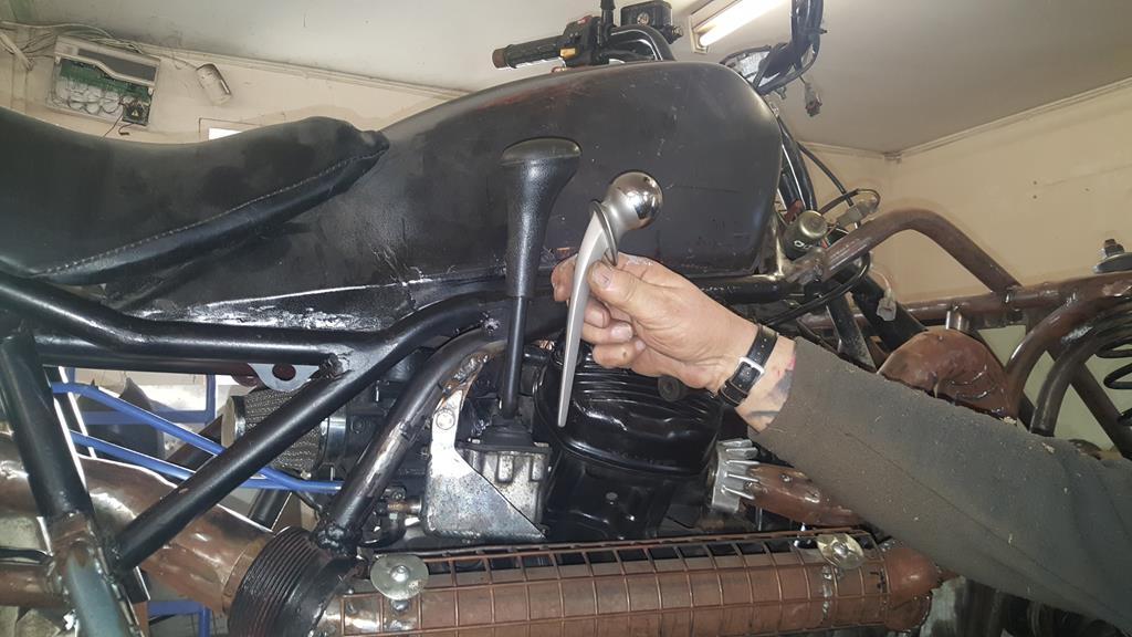 Yes it is what you think it is... A titainium hip joint 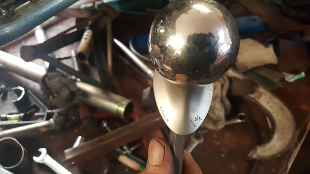 Now's a good point to drop in the latest MadTrax video.. Enjoy |
| |
My YouTube Channel www.youtube.com/user/UkWheelHorseBlokeQuote - D'you know, it's people like you, doing totally brilliant and pointless stuff like this that gives me a little hope for humanity |
|
|
|
|
Jan 17, 2018 20:58:49 GMT
|
This is insane. You have some awesome skills mate. You must be a genius to come up with your ideas.......or bonkers...maybe both a bit. Loving this thing anyway Thanks rblote, I'm not sure on the genius bit, but bonkers I will put my hand up to As someone has put a transfer box right in the way Don't you just hate it when they do that? As ever, top work! Thanks George, what I can't work out is why it's always me that puts something in the way on my builds.. It would be nice to blame someone else for a change Hi all, I'm back after taking a break from the internet for a while, sometimes it has to be done to try and keep some sanity Back to the exhaust system.. In order to find a bit more space around the transfer box I moved the end cans back by about 3 inches.. 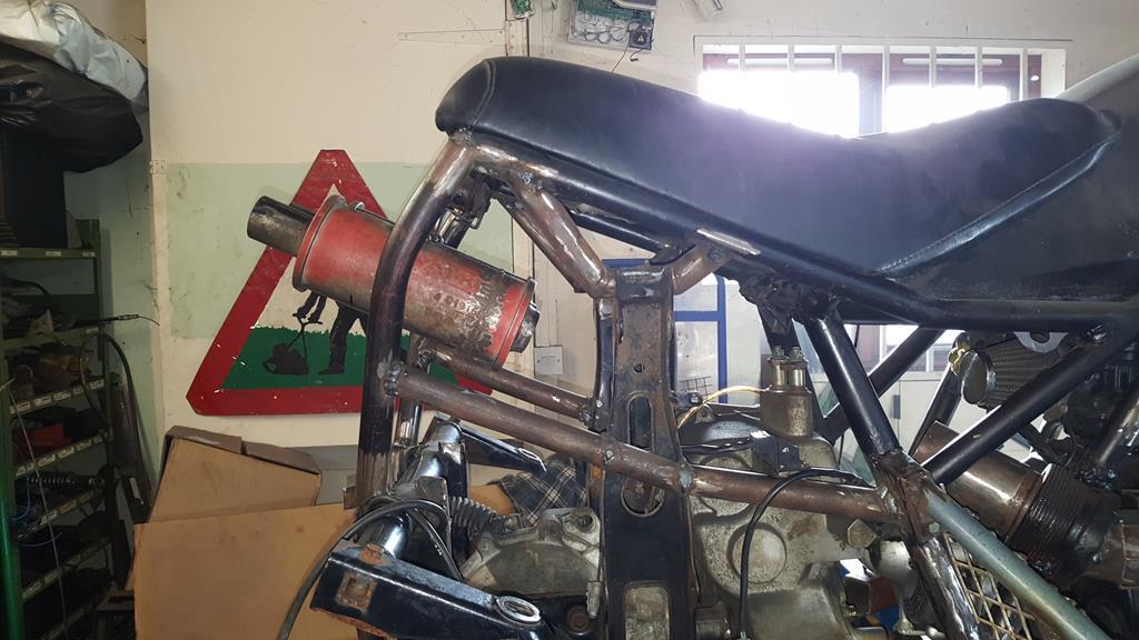 This was one of the end can mounting brackets.. 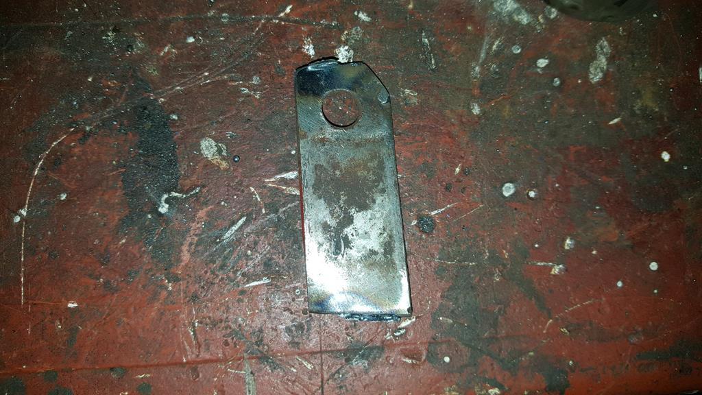 These are the upgraded versions, stronger and look much better. 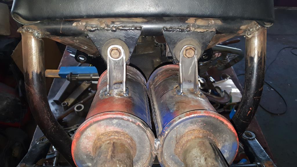 Some more slicing and dicing of tubes saw both end cans plumbed together.. 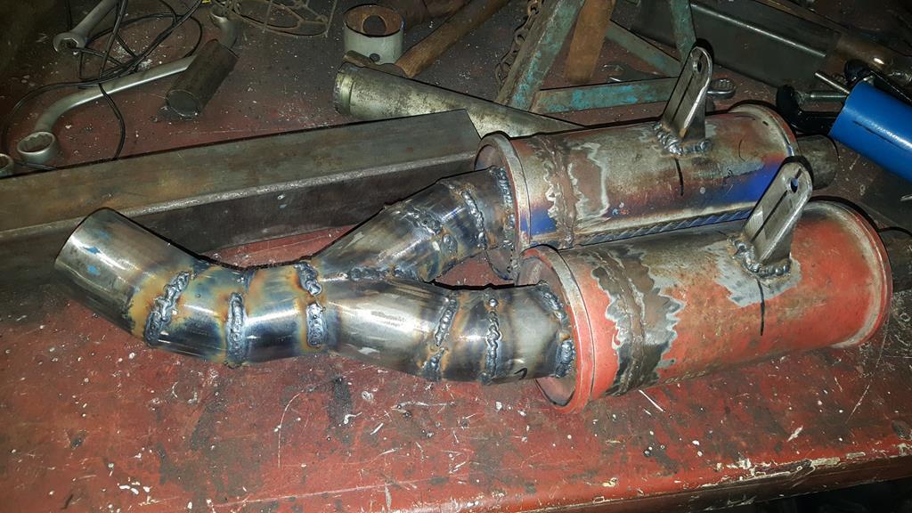 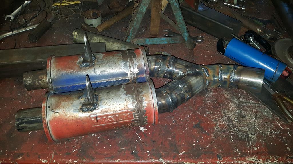 The solution to joining the front and back pipes together was this ear trumpet shaped bit of pipe.   It's a tight fit around the transfer box, a very thick ally heat shield will be going between the exhaust and the black electrical gizmo with the word up, upside down.. Don't want to melt it! Thinking on it, if it's only an idiot light switch it wouldn't be hard to rig up another switch on the shifter linkage and do away with the one that's a bit too close to the exhaust..  Apart from grinding down lot's of welds that's the exhaust system done  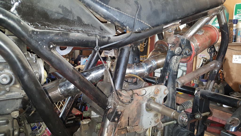 Next on the hit list to sort is the shifter for the transfer box.. 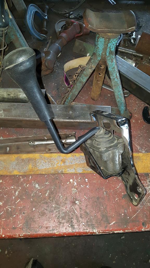 It needs to go somewhere around here, also the bracket looks really ugly so a new one is being made.. 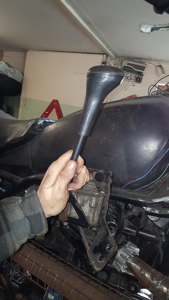 The fun bit is going to be making the rods that connect it to the transfer box, but luck might be on my side as I found an easy route through the frame, above the carbs that will require minimal bends to the rods.. Oh, a scrap pile raid produced all the rods I could need  Have a moody smokey picture of the MadTrax 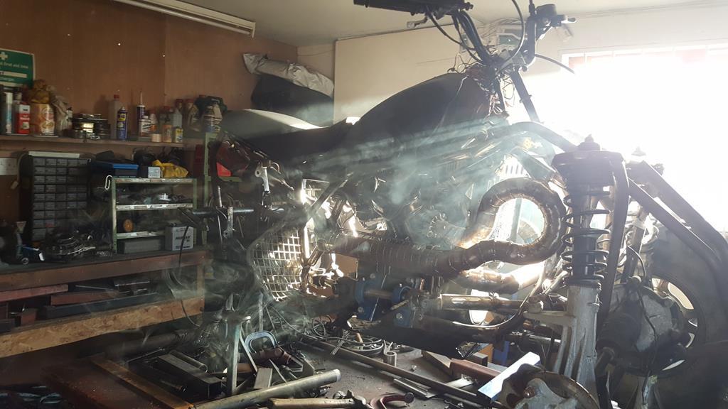 |
| |
My YouTube Channel www.youtube.com/user/UkWheelHorseBlokeQuote - D'you know, it's people like you, doing totally brilliant and pointless stuff like this that gives me a little hope for humanity |
|
|
|


