|
|
|
Oct 10, 2018 10:26:07 GMT
|
The system worked just fine for panning along side to side though the fencing wire was starting to develop lots of little kinks.. So I thought I'd best try things up and down.. Yes I was in position to catch the video camera should anything fail and gravity makes things plummet during testing.. These two photo's were taken in record time  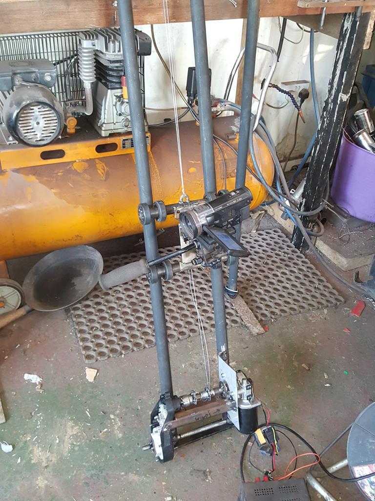 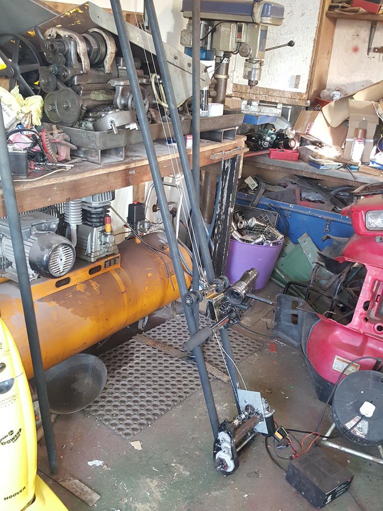 As the electric motor at the time was 12 volt, it made it easy to try it out outside.. 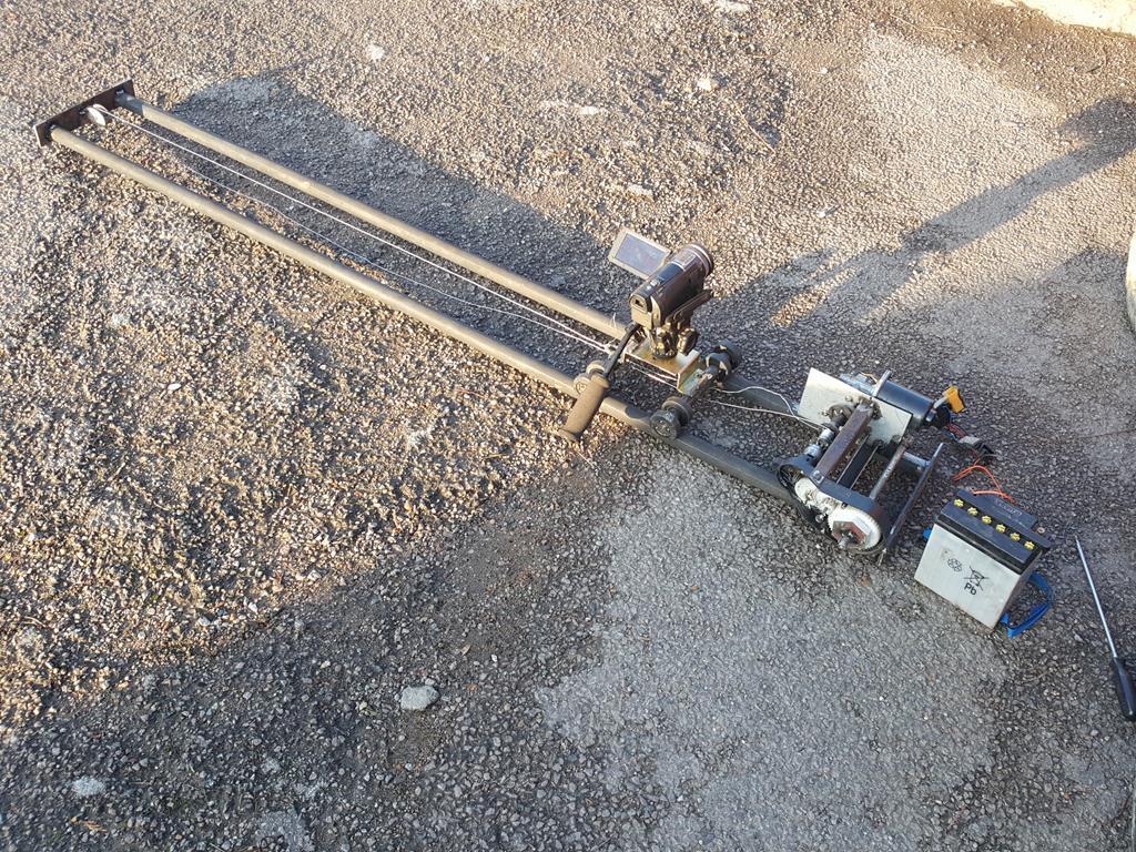 With it back on the bench for more testing the thin fencing wire decided it had had enough of having lots of little kinks forced onto it and showed it by snapping! I also wasn't that happy with how the pulleys worked. The ultra slow side of things was really ultra slow like the camera moved 1 ft every 20 mins sort of ultra slow! The New Holland tractor wiper motor made all sorts of squealing sounds when it's speed was turned down and it would of been a pain in the 'orse to have to disconnect the drive wire/string from one pulley shaft to another to get different speeds... Sooooo, a rethink was needed... Hidden under the yellow rag (which is wrapped around to try and quieten gear noise a bit) is the 18 volt motor from the rechargeable drill that gave up it's speed controls. It powers the kiddys electric car gearbox to turn a single shaft which is now held up one end by a bearing and plate that came from a Webb cricket pitch mower years ago.. It pays to throw nothing away As you can see the whole thing is now rubber mounted to the rails to reduce the amount of running sounds the camera picks up. 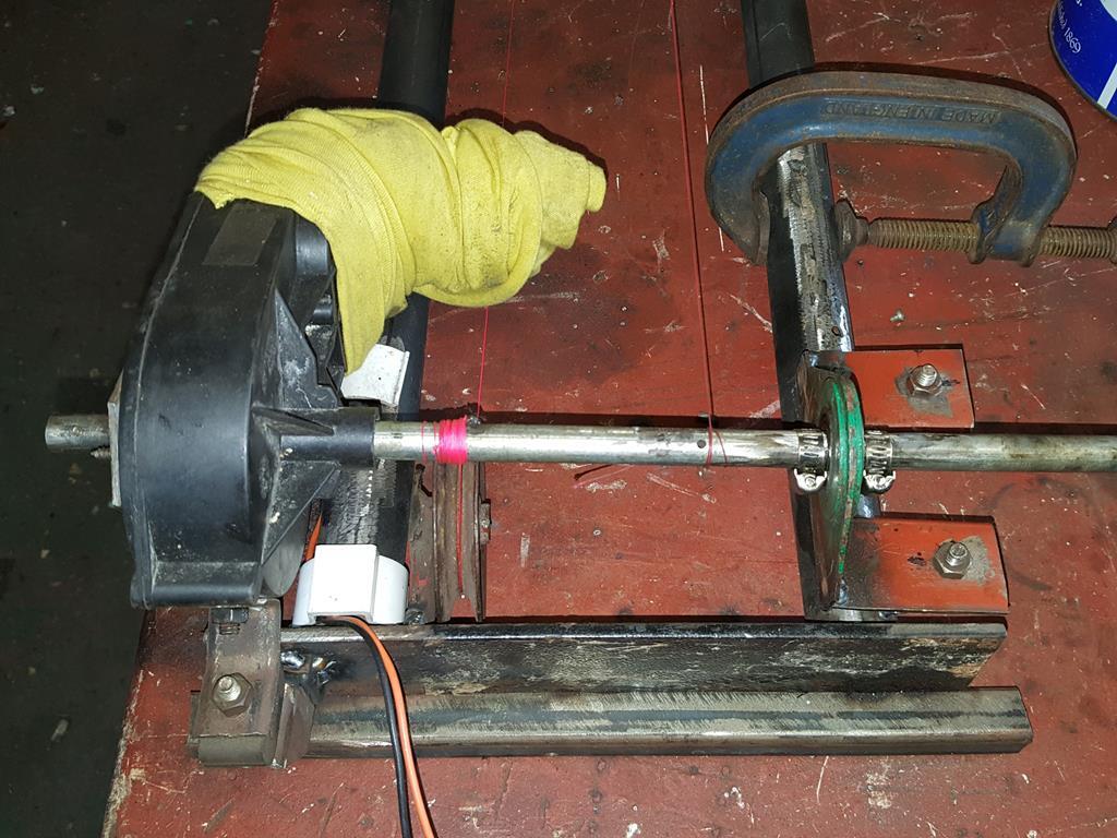 A big thank you to Matt for donating some strong fishing line to the cause, it now winds both ways on the shaft, so when one side is winding in the other is winding out. 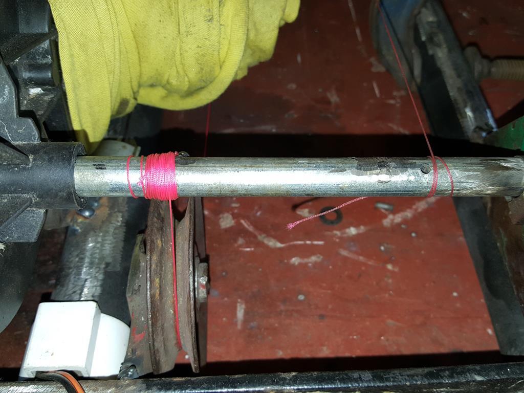 The speed control is a work of art and is more than worthy of the two photo's it's getting.. As I am using the trigger speed control from the 18 volt rechargeable drill I needed to find an accurate way of applying pressure of varying amounts to the trigger and keep it there.. The easiest way I could think of was a clamp of some sort.. Like the exhaust clamp with a bit ground out to fit the trigger.. Just tighten the nuts to increase the speed. A washer was welded on to house a master on off switch 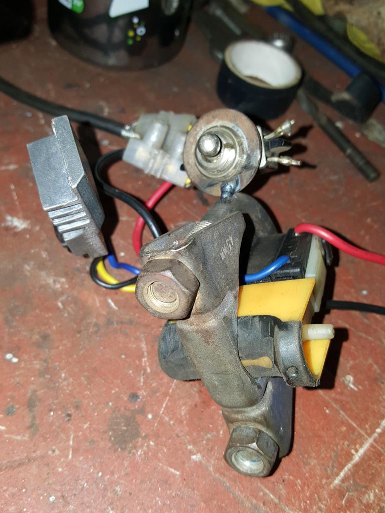 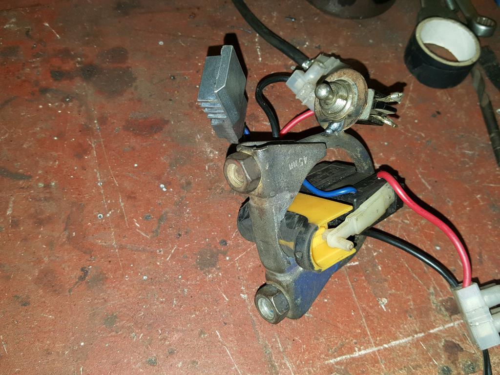 Power is now supplied by this 18.5 volt HP power pack that I found in a box in the workshop.. No idea where or when I got it, but it has come in handy. 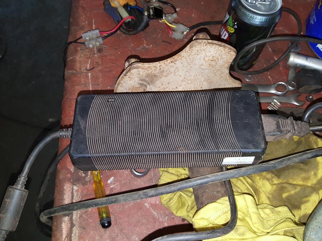 So with everything finally ready to go, the jig thingy was put in a position up high, video camera clamped in place on the carriage and the comical electrical system plugged in... It was at the point I managed to knock a stand which was holding up one end and it all came crashing down with a loud bang! Nigel and Matt came running to see if I'd done anything nasty, but soon hastily retreated once they saw me stomping about the place swearing a lot! Somehow my video camera didn't get broken, not even a scratch, but the jig thingy did need some repairs! One of which was to repair the end of the winding shaft which had had a threaded end sheered off! To make the shaft long enough again I had to lengthen it.. It was at this point I had an idea and left the shaft over length for another idea.. More on that when it happens. 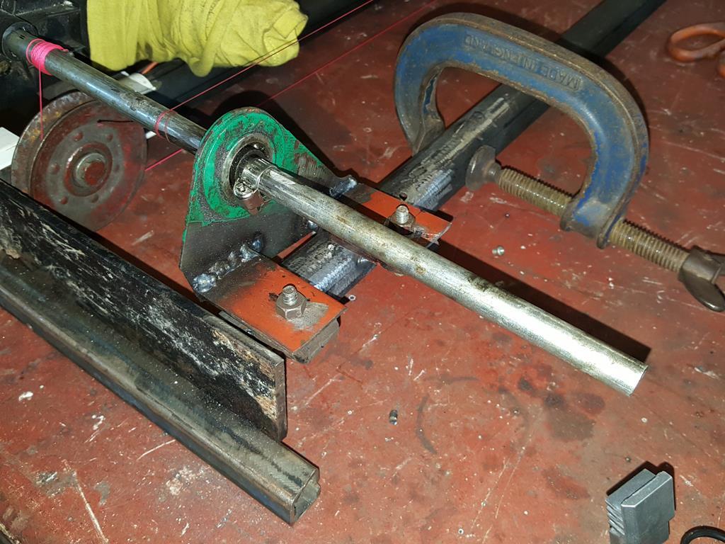 So does the camera panning jig thingy work? Well, here's a couple of snaps after some successful testing..... 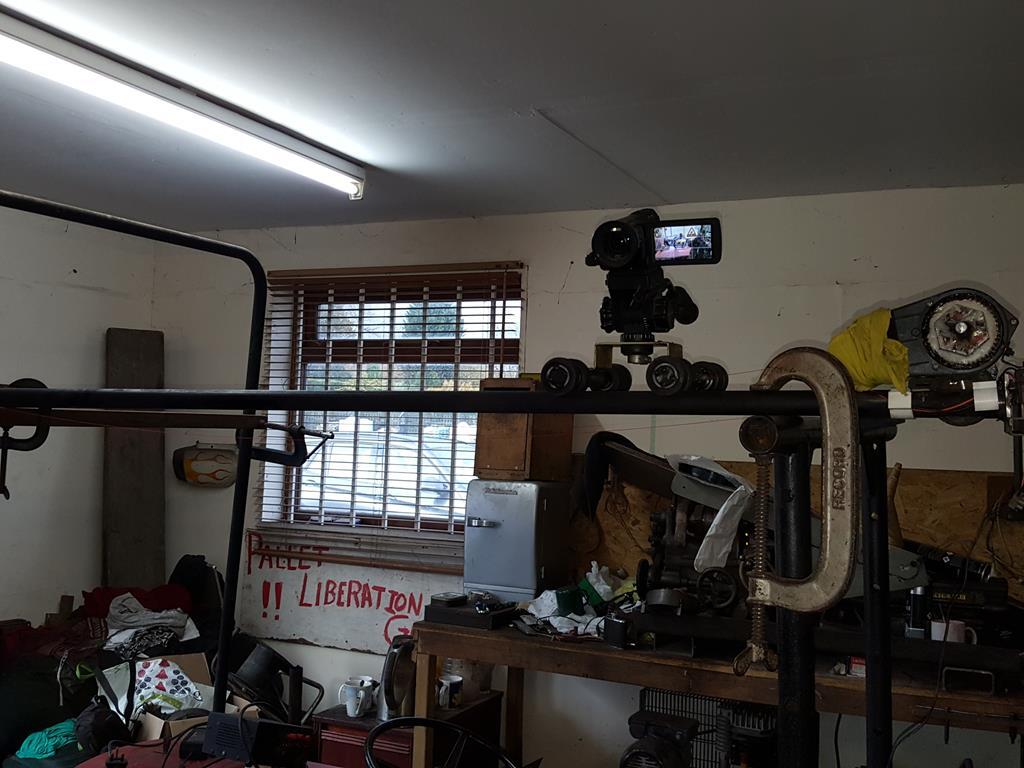 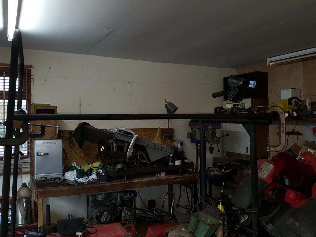 That was almost 2 years ago... |
| |
My YouTube Channel www.youtube.com/user/UkWheelHorseBlokeQuote - D'you know, it's people like you, doing totally brilliant and pointless stuff like this that gives me a little hope for humanity |
|
|
|
|
|
|
Oct 10, 2018 10:07:49 GMT
|
Back to the drive train if you can call it that lol.. To get the ultra slow panning side of things working I needed to find a way of fixing the small electric car motor to the New Holland wiper motor.. A bit of round bar with a 3mm diameter drilled in it.. The bar was then heated up (ta for the use of your blow torch Nigel) and expanded so the 3.2mm shaft of the electric motor could be press fitted in. 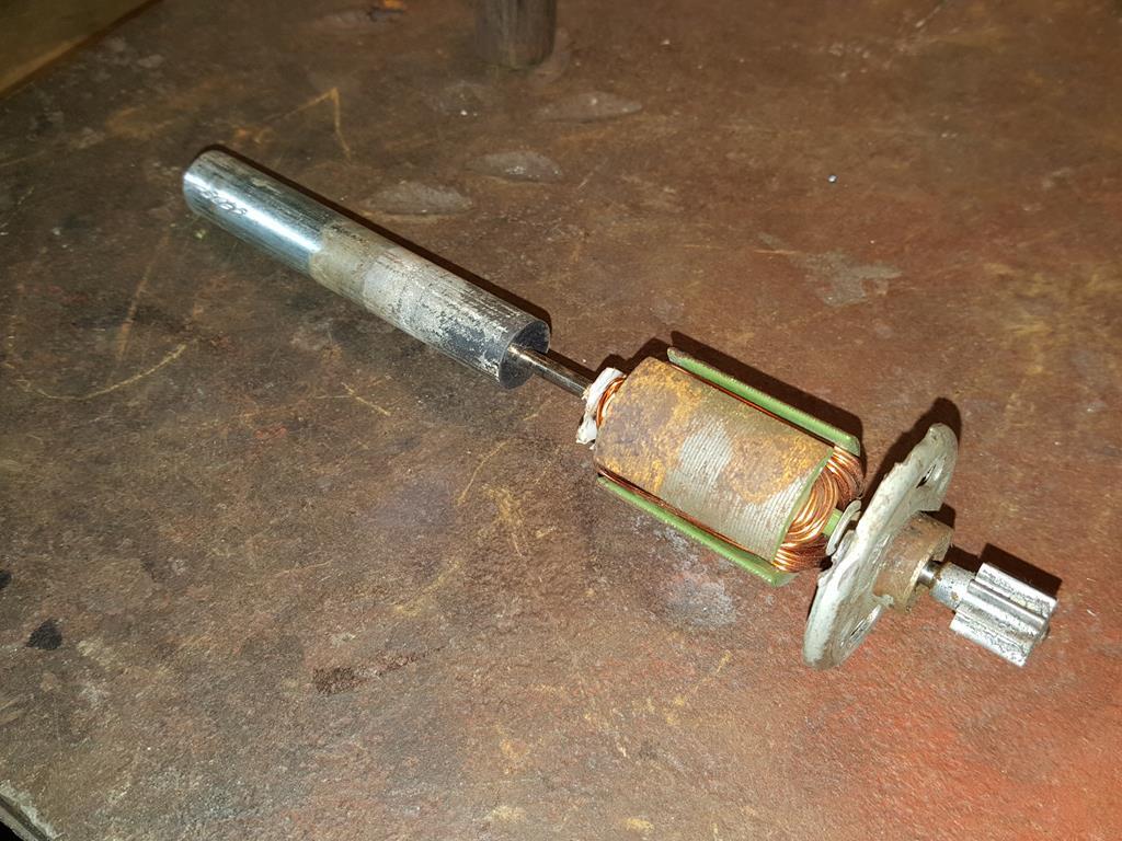 A bit of tube with a 13mm nut welded on. 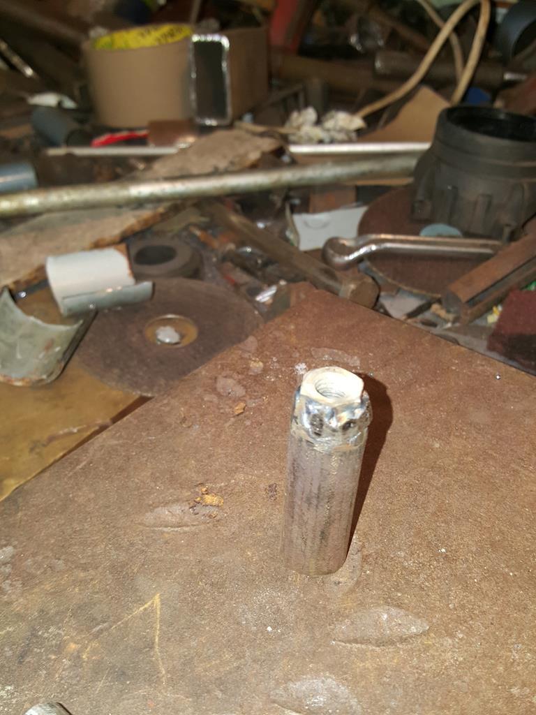 Which is a tight fit on the bit of bar. Once the tube is welded to the bar the nut end winds onto the wiper motor. 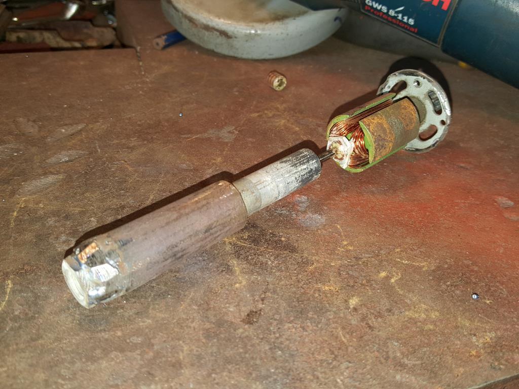 Taa daaaa... Drive into the gearbox for the ultra slow speed side of things. 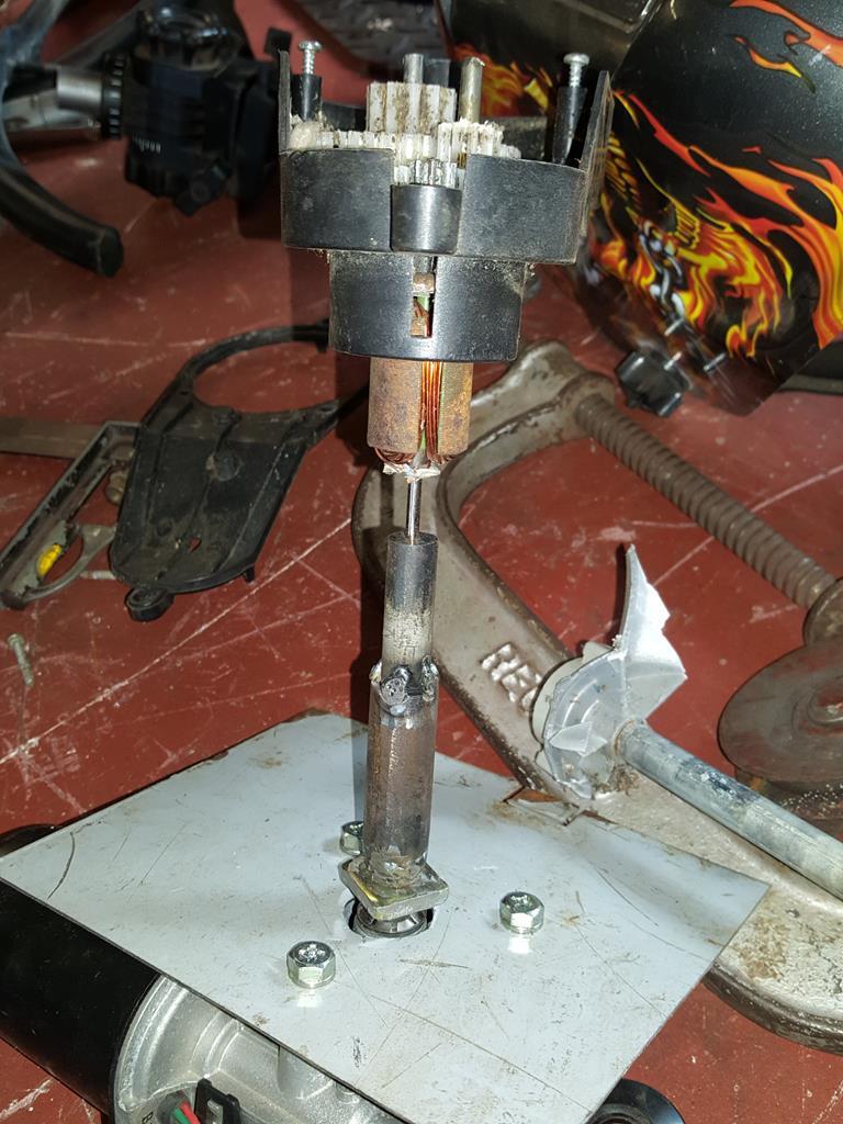 To get drive out of the gearbox I needed to find a way of fixing a bit of this bar to this sprocket. 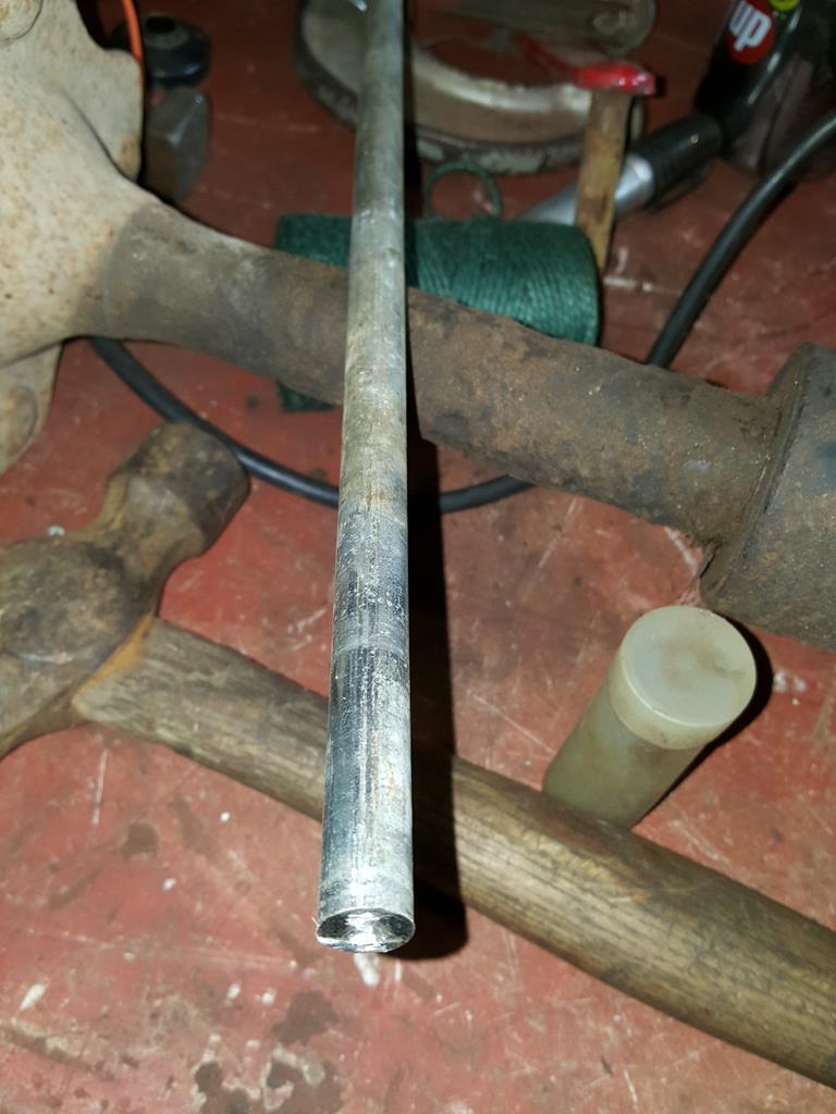 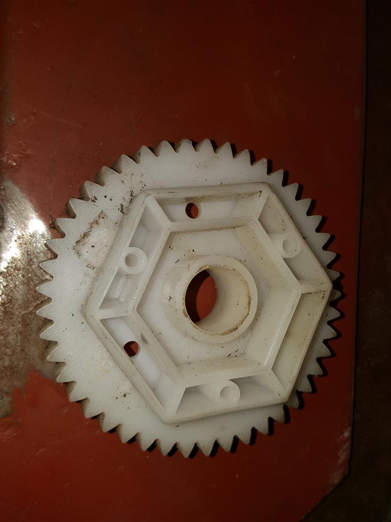 A masking tape template, shame I forgot to photo the steel version as well! 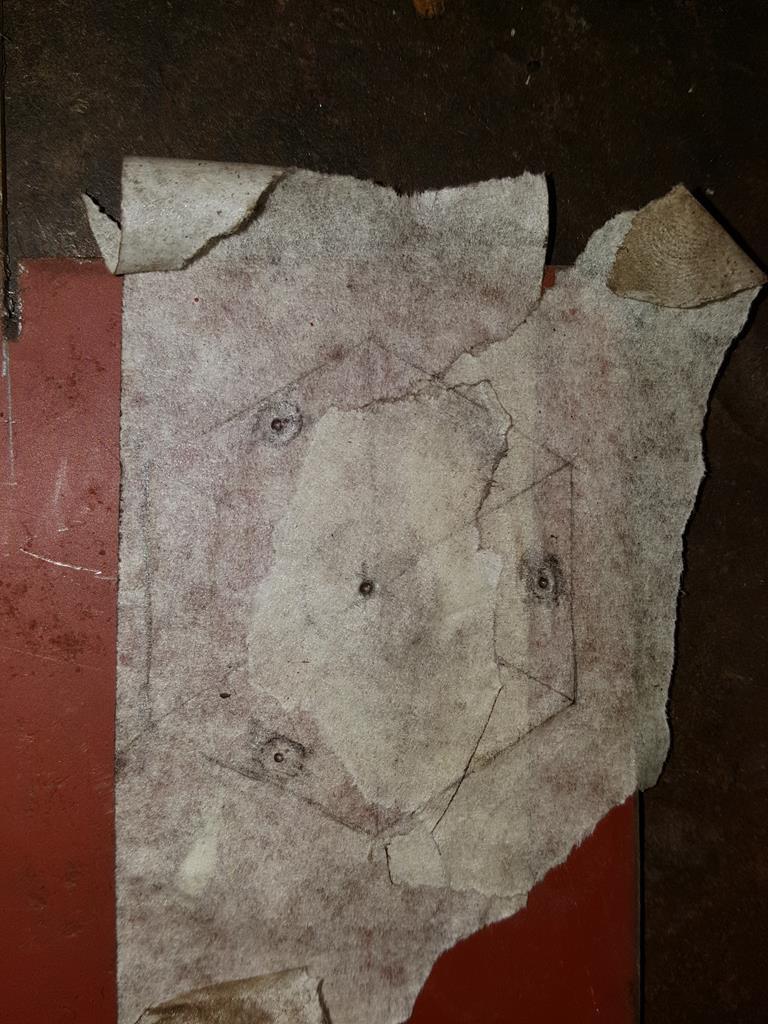 The basic motorized system, and yes the far shaft needs a tweak to get it straight.. The idea is you can tie a bit of string to the shaft coming out the wiper motor to produce a nice workable speed.. Move the string to the far shaft and the gearing is such that it would take about 30 mins maybe more to pull the camera carriage up the rails.. Just right for time lapse stuff. 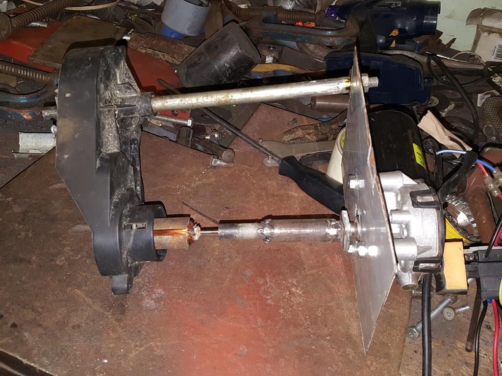 You saw the masking tape template of the part I forgot to photograph, well here's the part finally photographed.. Screws go though the cog and screw into captive threads in the 6 sided er... boss which is welded to the shaft. It has been re-welded since this photo was taken.. 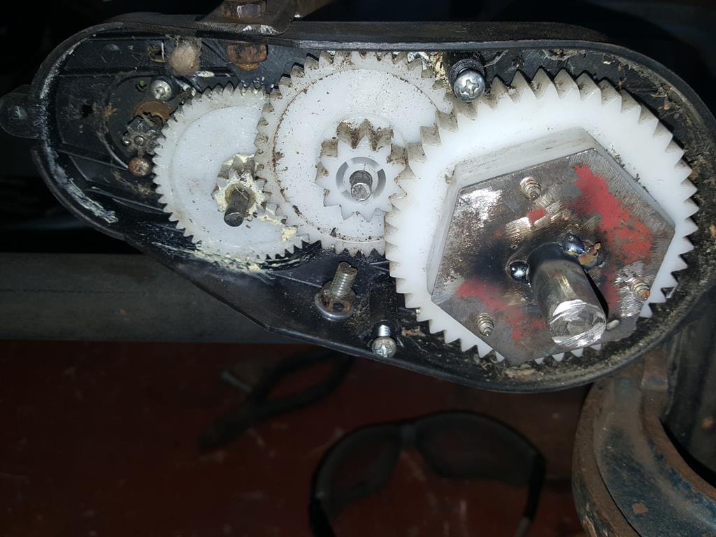 With the winding shafts sorted so they run parallel with each other the whole lot was welded to one end of the rails. 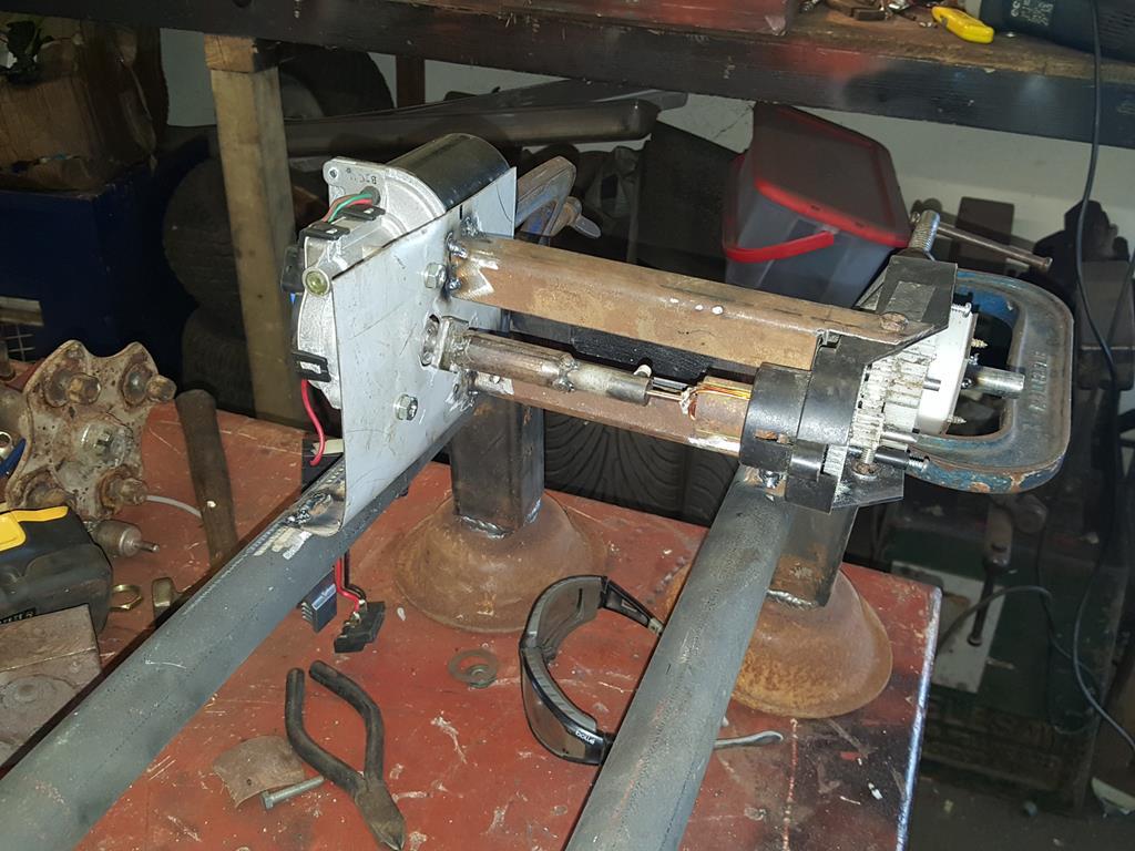 The other end got a pulley.. 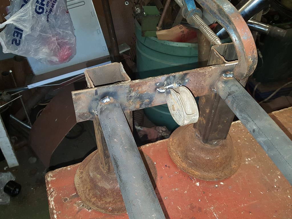 One of the shafts was then taken back off for some serious strengthening and a few guiding washers. The green garden string I had bought was useless and kept breaking, so I tried some thin fencing wire which I happened to have kicking about the place. 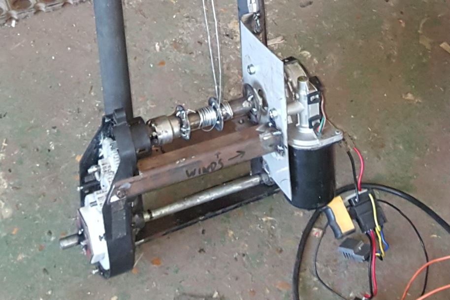 |
| |
My YouTube Channel www.youtube.com/user/UkWheelHorseBlokeQuote - D'you know, it's people like you, doing totally brilliant and pointless stuff like this that gives me a little hope for humanity |
|
|
|
|
|
|
As I'd cut up the wiper motor bracket to make the camera carriage thingy, I needed to make a new one.. The shape will change a bit when it gets mounted to the rails. 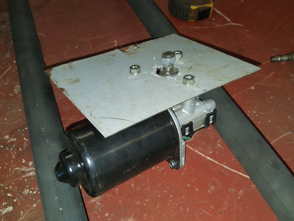 Here's the gearbox from the kiddies electric var that I forgot to take a photo of.. All that gearing will slow things down very well, ideal for time lapse videos. 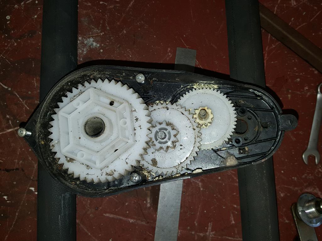 The missing sprocket from the gearbox is fixed to the electric motor shaft.. I don't need all of the motor so out came the grinder. 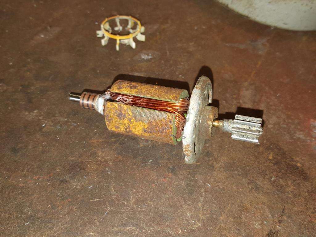 It was at this point that I decided the time had come to look for for an old inner tube to make some tyres out of. I couldn't see anything with bike wheels on it in the scrap pile, so I had a drive looking for some rubber coolant pipe to use... 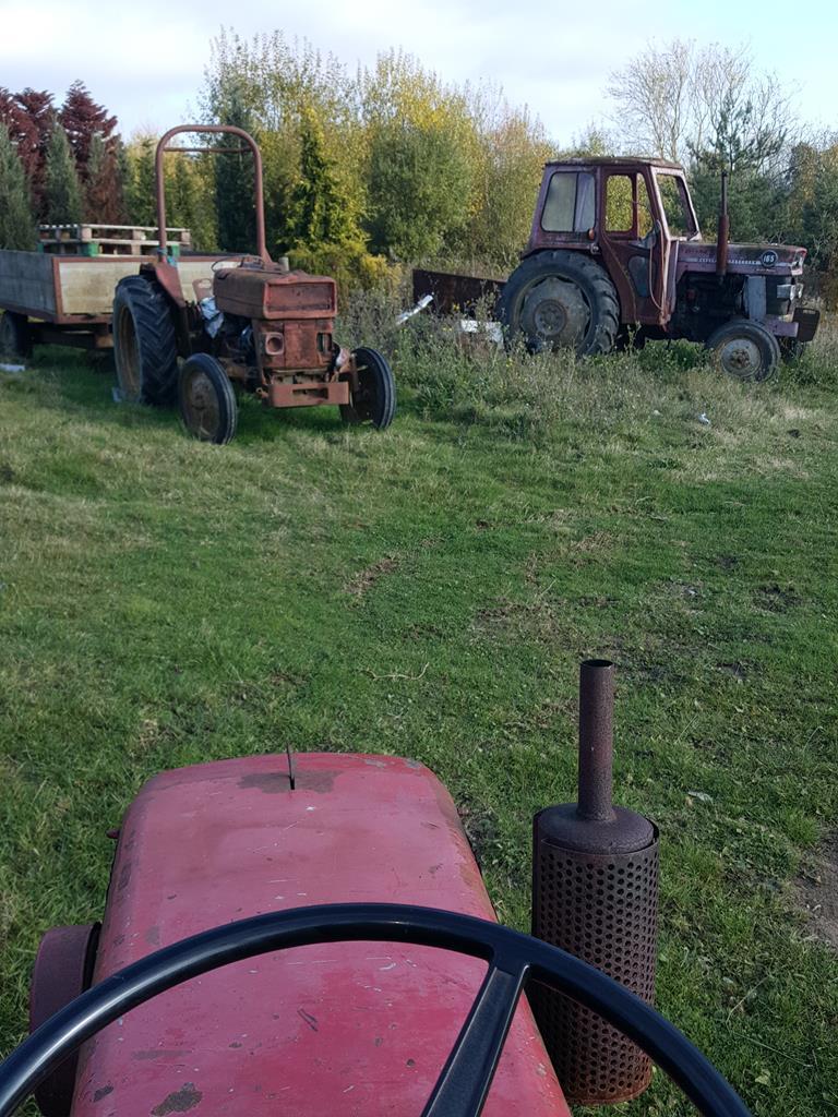 Fear not, the Fergies are safe. It was these two Escorts that I was interested in.. The estate while easy to get into was not going to give up any of it's internals as the bonnet pull lever inside refused to budge! The saloon I knew had an opening bonnet but without cutting down any trees only the driver door would open.. About 6 inches! Lot's of unnatural body positions later I just managed to get my arm in and pull the latch.. It's a shame that when I opened the bonnet I found the water pipes way too small! 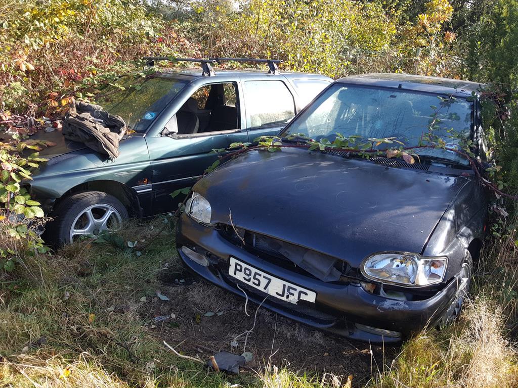 Oh well, best have another look at the scrap pile as it's on the way back to the workshop.. This time I got off my Wheel Horse to have a real good look.. Then I spotted it buried under loads of junk and long grass. Hurrah  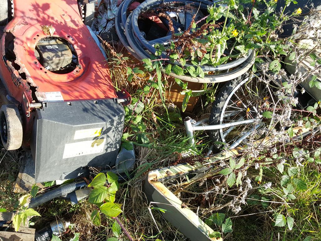 That was a very cold day weather wise so naturally the first thing to do when I got back to the workshop was to make a coffee  And bask in the glory of finally finding an inner tube. 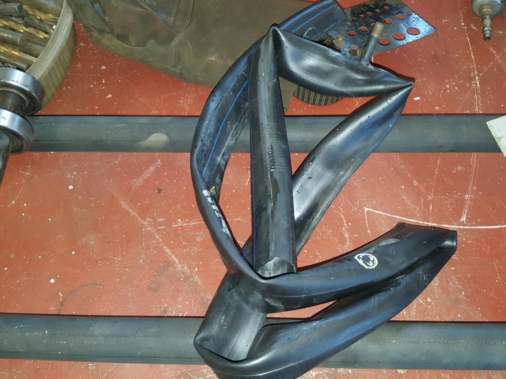 Once the coffee had warmed me up I sliced a bit off the inner tube and with a lot of stretching it slid onto the bearing.. Instant tyre  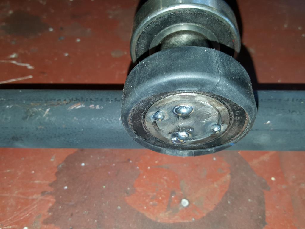 I will try a wider bit of inner tube to see how well it wraps it's self around the bearing.. As you can see the bearing only really make contact with the rails on it's outer edge, so the more the tube wraps it's self around the better.. I'm not a fan of the really low profile tyre look anyway  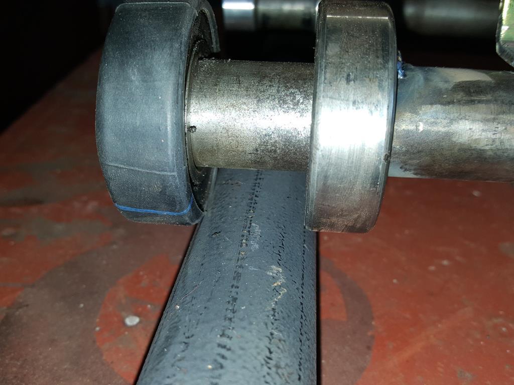 |
| |
My YouTube Channel www.youtube.com/user/UkWheelHorseBlokeQuote - D'you know, it's people like you, doing totally brilliant and pointless stuff like this that gives me a little hope for humanity |
|
|
|
|
|
|
Morning all, for some reason I have never posted anything about this build on RR (if I have I can't find it anywhere), so the first part will be copied and pasted from another forum to give you the whole story.. Starting almost 2 years ago! I have started a little project that I have been meaning to do for a long time, a panning camera jig thingy.. This should make my videos look more professional and hopefully make them more enjoyable for you all to watch... The first part needed was the gearbox out of this very old and abandoned kiddies electric car.. I forgot to get a photo of the gearbox so here's a pic of what remained of the car when I'd finished cannibalizing it. 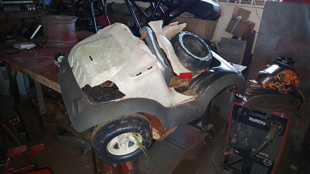 While dumping the remains of the car on the rubbish pile I thought I'd have a quick look at the scrap pile... Hhmm... Those tubes could come in handy 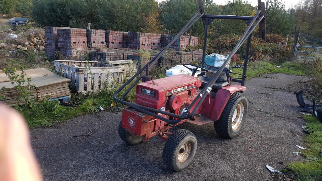 Back in the workshop some choppy weldy later, a 8 inch wide tubular track was made. 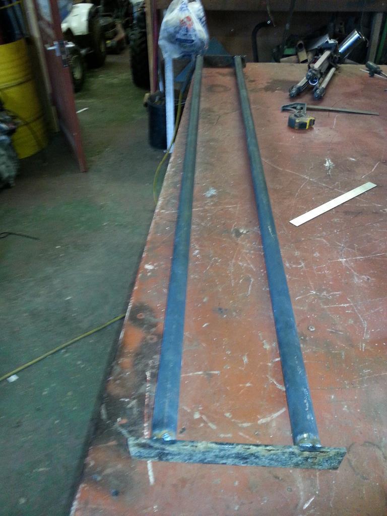 Now I needed something to roll along the track, a sliced up cart axle and some used bearings got things rolling.. Yes I did commit the sin of welding the bearings to the axles, but the bearings feel the same as before the welding so hopefully all will be well. 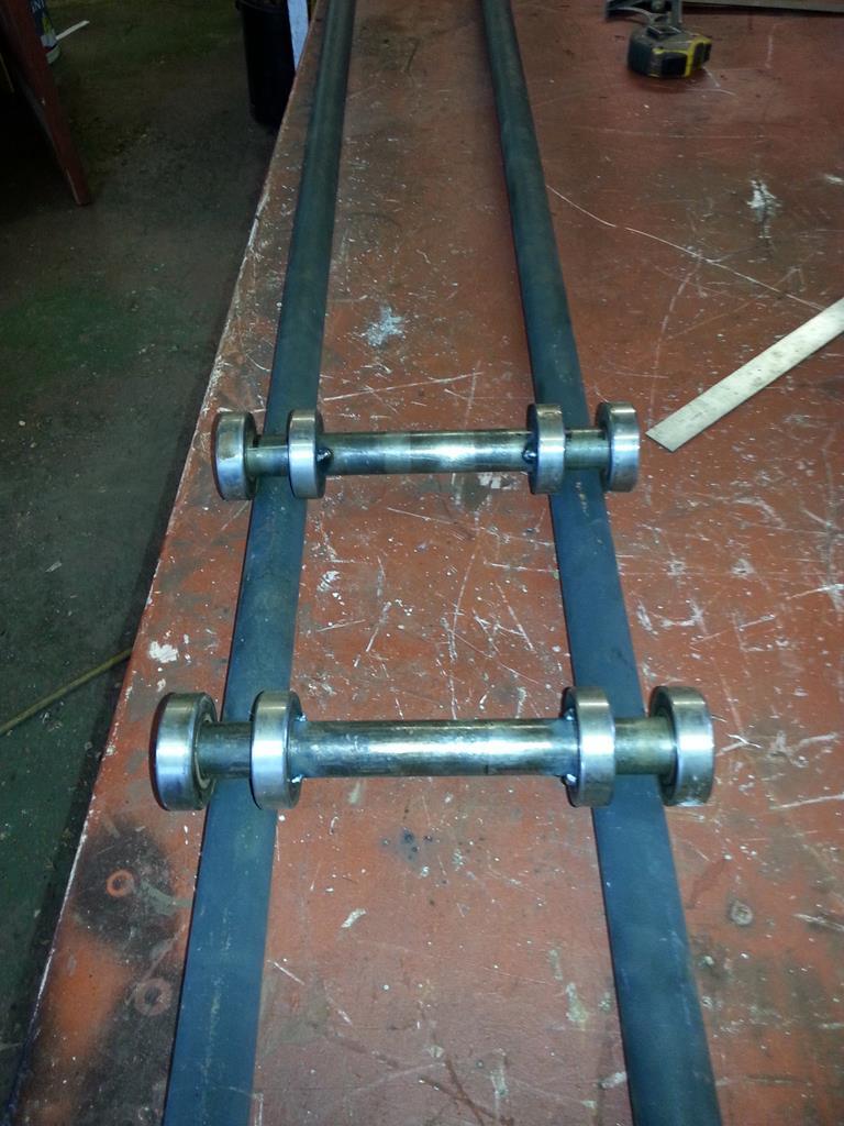 Something to mount the camera would be handy, so an old tripod got the chop. 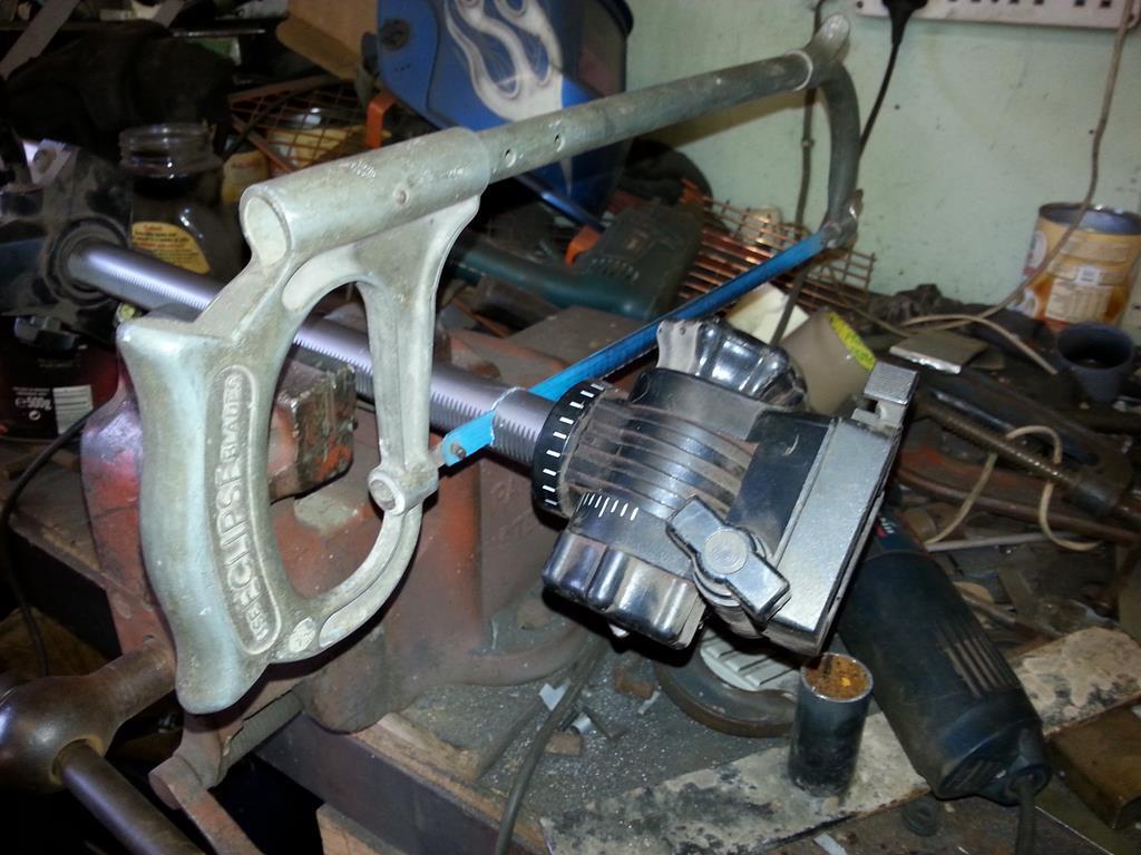 To motorize the contraption I am using a CB radio power pack, a New Holland tractor wiper motor and the speed control gubbins from a rechargeable drill that has knackered battery's. 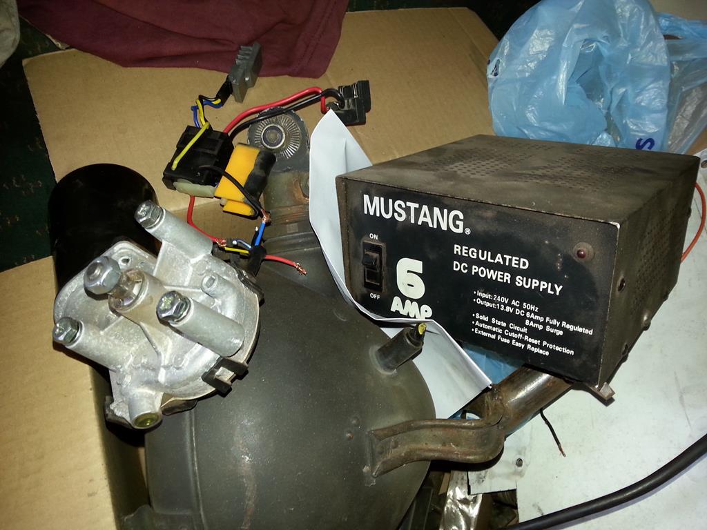 The two axles were joined together by using a cut down New Holland tractor wiper motor bracket which just happened to have the right size hole to fit the tripod cut off. As you can see the wiper motor isn't fully fitted yet. 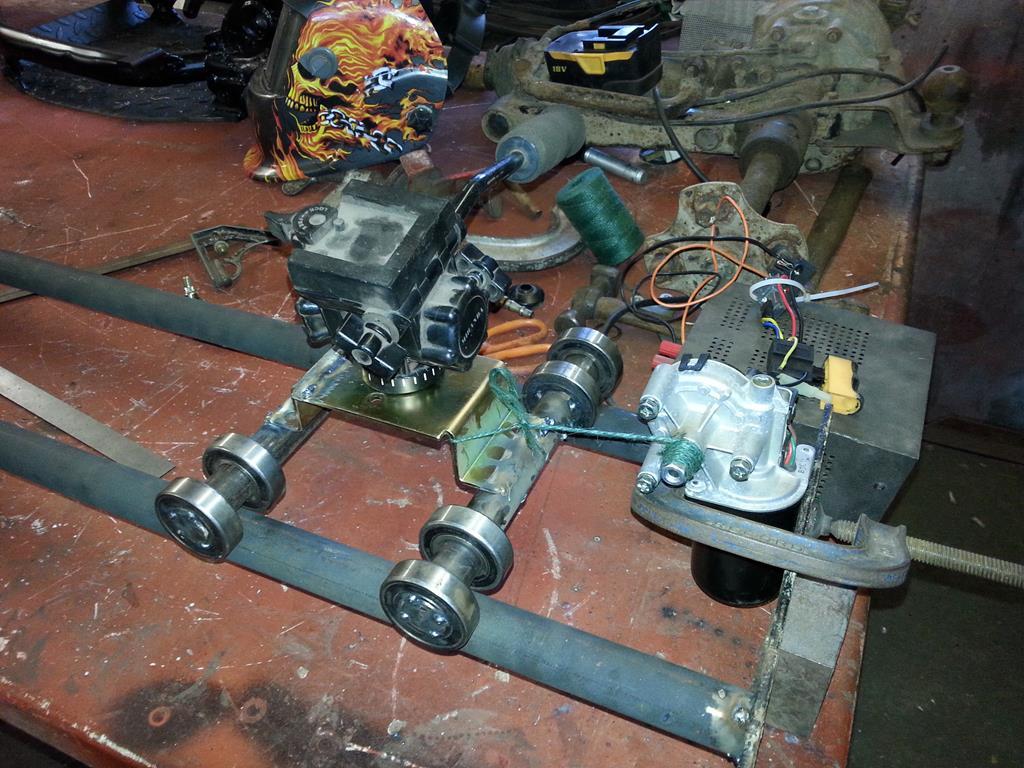 The idea is the wiper motor slowly winds a length of string onto a shaft and pulls it along the track.. The speed control does work but the motor does make some squealing sounds at slower speeds.. Something to have a think about.. I will add the electric car gearbox to slow things really down whilst doing time lapse filming. 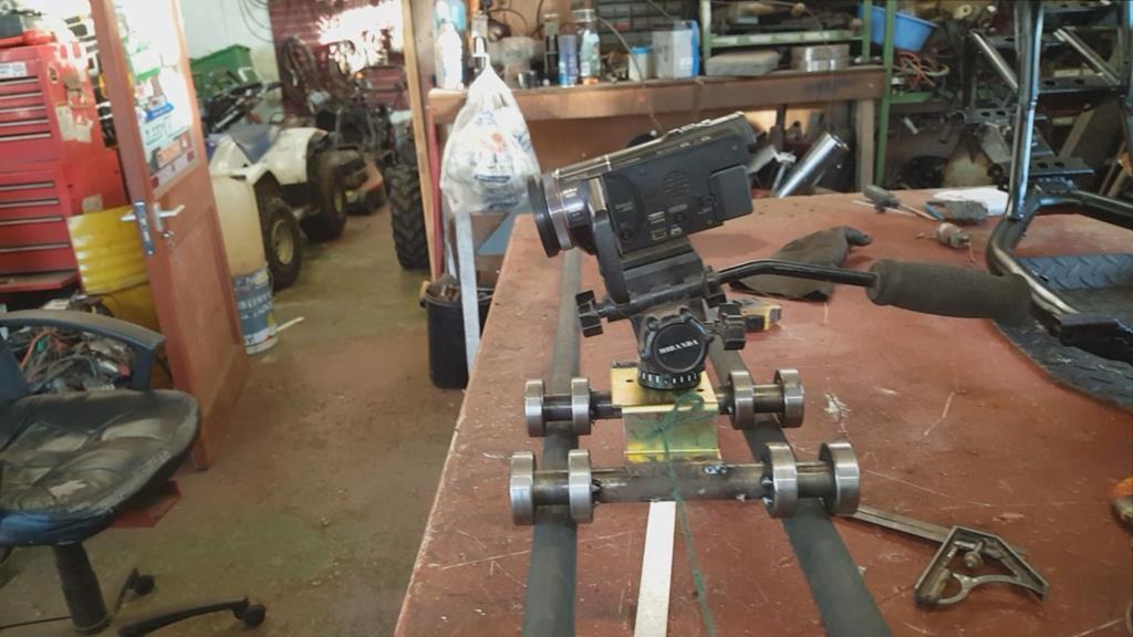 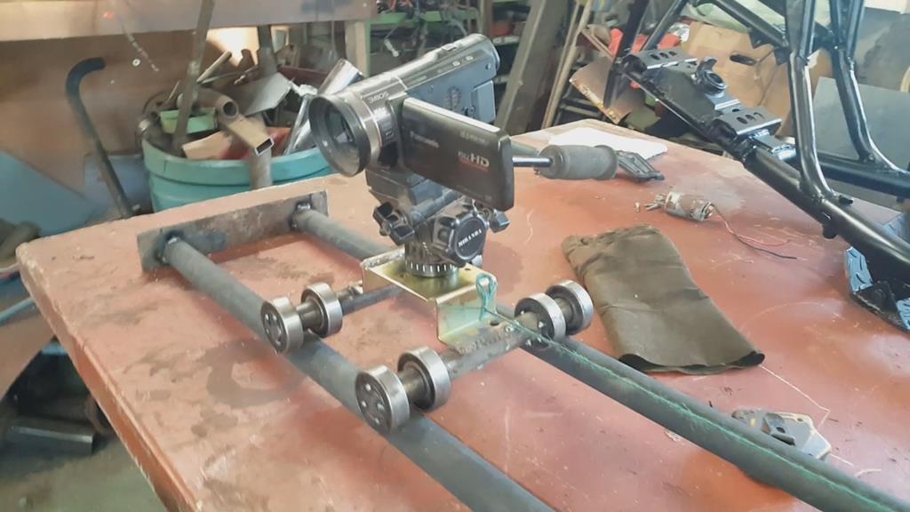 |
| |
My YouTube Channel www.youtube.com/user/UkWheelHorseBlokeQuote - D'you know, it's people like you, doing totally brilliant and pointless stuff like this that gives me a little hope for humanity |
|
|
|
|
Sept 24, 2018 7:06:44 GMT
|
|
|
| |
My YouTube Channel www.youtube.com/user/UkWheelHorseBlokeQuote - D'you know, it's people like you, doing totally brilliant and pointless stuff like this that gives me a little hope for humanity |
|
|
|
|
Sept 23, 2018 10:27:16 GMT
|
For some reason I forgot to take load of pic's of the next stages, so the photo's might seem a bit random.. This bearing holder needed a few mounts.. Two mounts this side.. 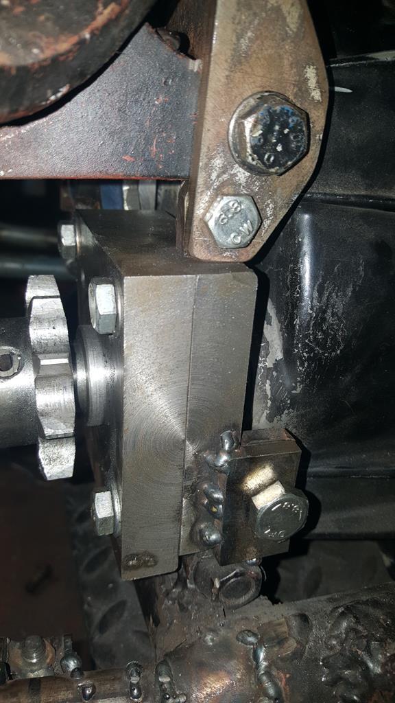 Making the mounts for this inside was more interesting, I also had to make lower mounts for the big blue bearing.. No photo's of this done but you will see it in the next video. 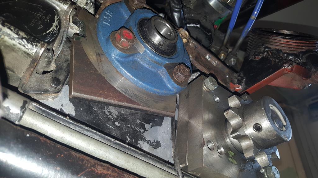 Chain half kinks and a sprocket turned up, this is part of the chain tensioner, so the sprocket was bored out to take a bearing each side. 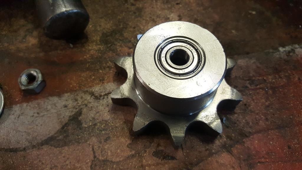 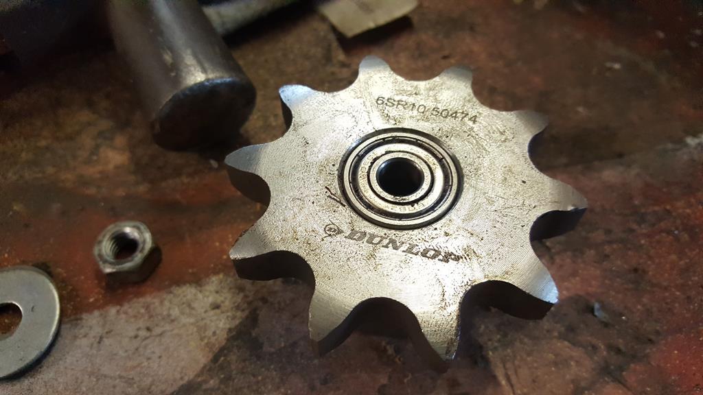 The transfer box idiot light switches were removed as the exhaust would melt them also they are not really needed.. 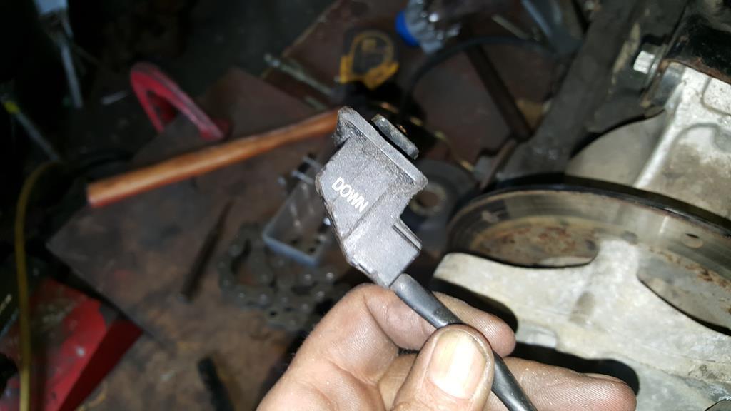 A couple of ally blanking plates blocked the holes back up. 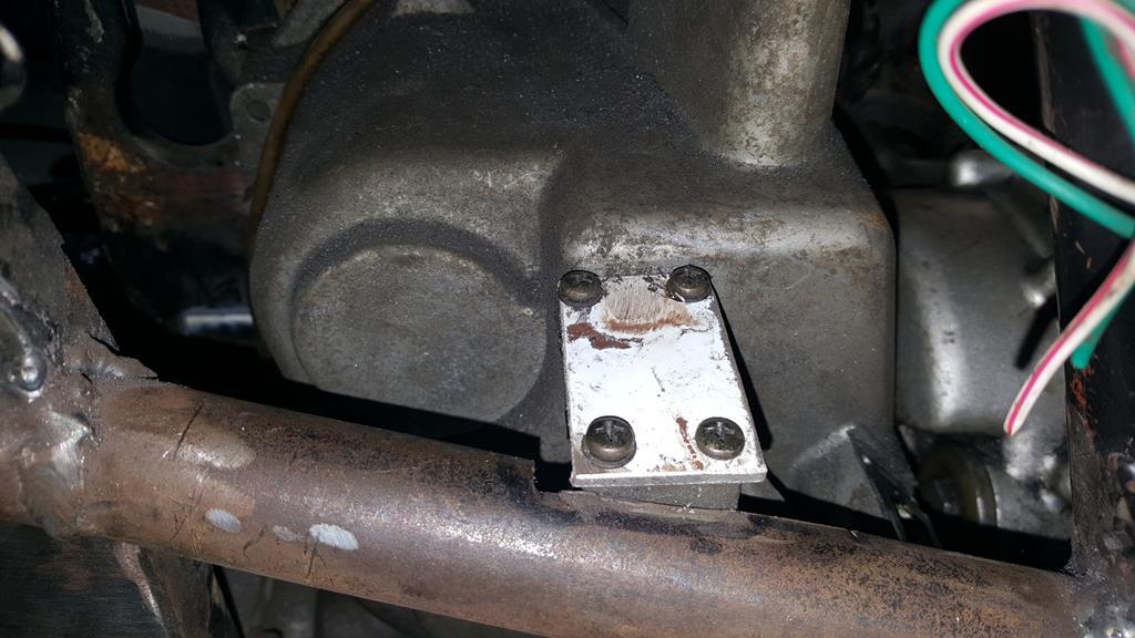 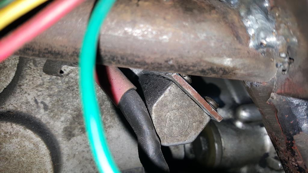 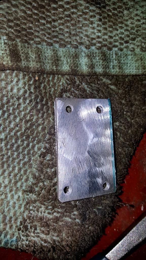 The finished chain tensioner thingy.. 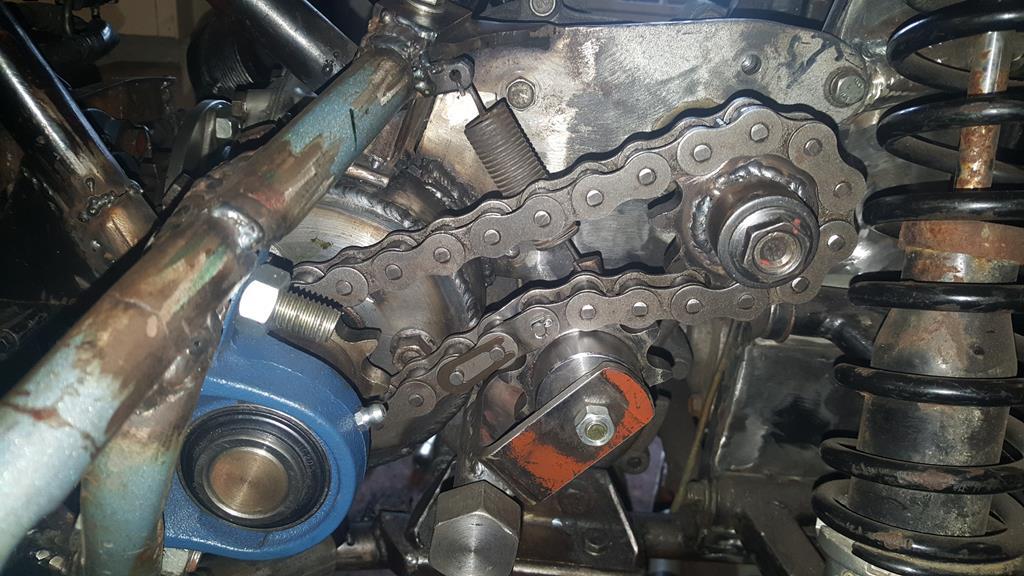 Right, that's enough of that.. Best explain things better in a video.. Followed by... Soooo did Madtrax drive??? Well your have to wait to find out as I've not edited the video yet :-D |
| |
My YouTube Channel www.youtube.com/user/UkWheelHorseBlokeQuote - D'you know, it's people like you, doing totally brilliant and pointless stuff like this that gives me a little hope for humanity |
|
|
|
|
Sept 23, 2018 10:05:37 GMT
|
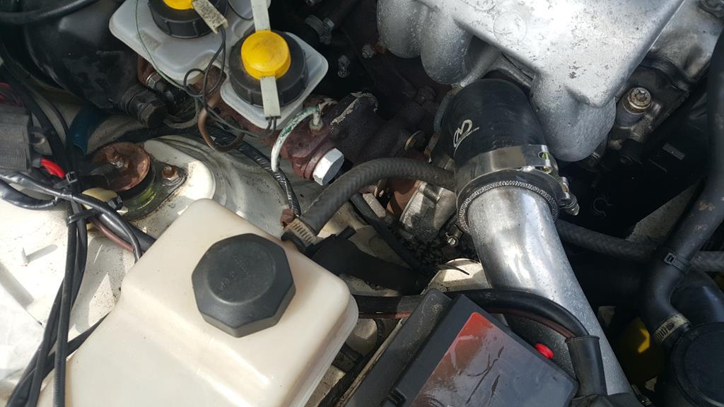
Yay, it's back! "...plenty of space..." is not something I expected to read in this thread - twice! As ever, it's great to see the thought process and skill going into this. "Plenty of space" could mean as little or as much as 1/4 inch with this build.. Right, let's get some more updating done.. Time was still lacking at this point but I did make a good start on the transfer box to from diff drive/prop shafts. I didn't take many photo's and even less video footage as I just wanted to get bit's done while I had the time. Holding a small shaft in place to measure up and work things out was a right pain until I quickly made this "bit of tube welded to box" which held the shaft in the right place. 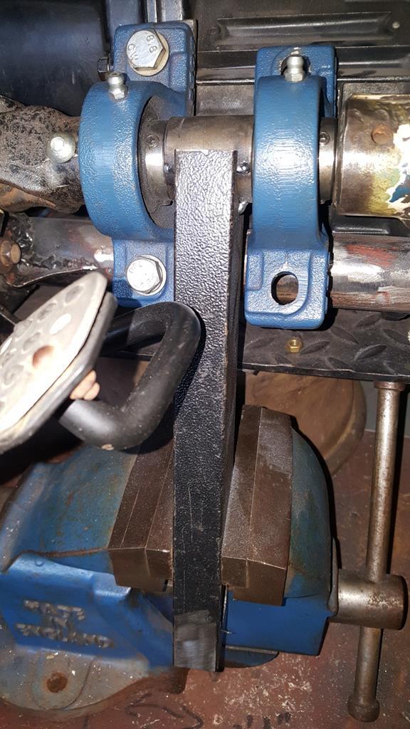 The shaft to the front had been extended and made a slightly bigger diameter to fit the new UJ.. Not welded up in this picjust in case any adjustment was needed. 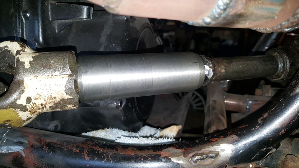 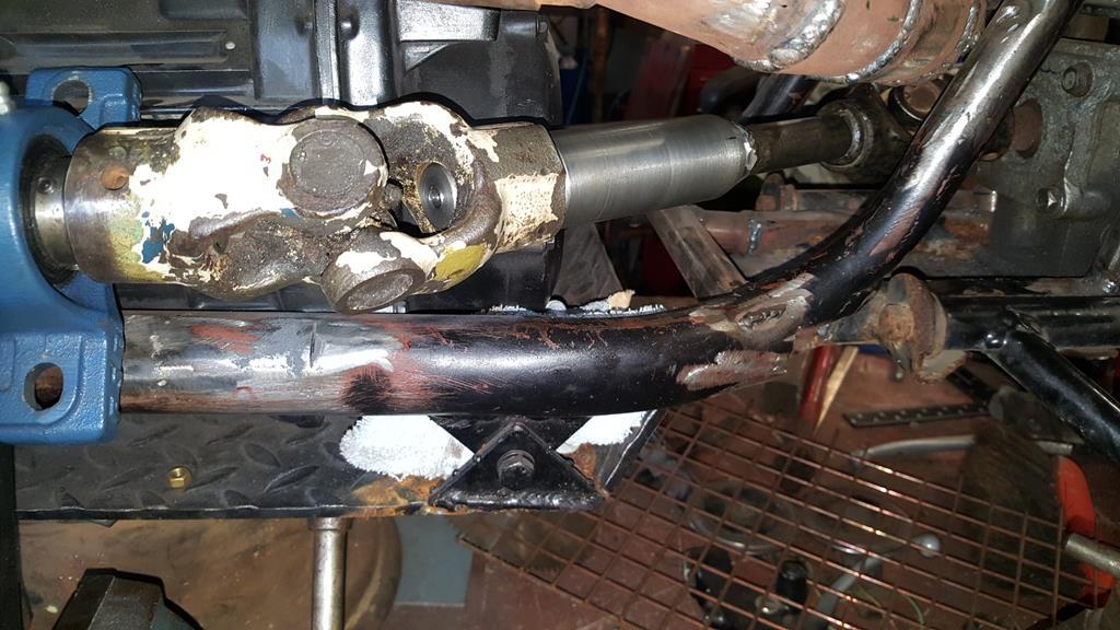 Here's one of the bearing brackets I made up.. Think it's going to need a lot of trimming now everything is a lot closer to the engine..  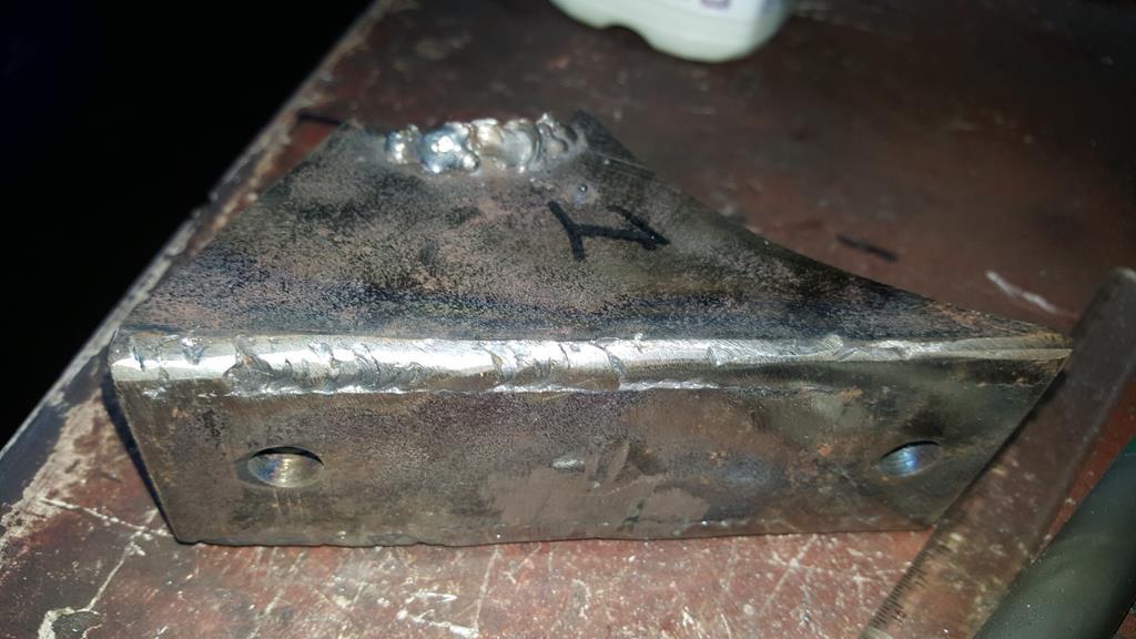 The original mounts were trimmed back until only the plates with captive nuts were left. Here they are bolted to the back of the bearings, ready to be tacked onto the frame. The random bit of angle is there to keep the tops in line. 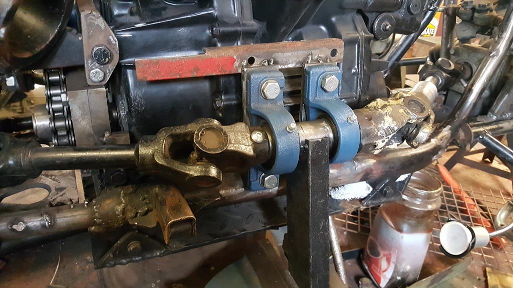 And without the bearings, just tacked on. 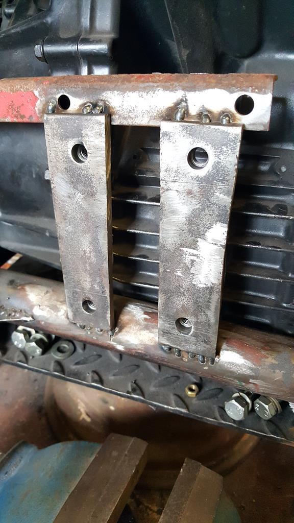 A bit hard to see in the next two photo's, the bearing mounts now have extra strength with gussets added.. As ever not fully welded in these pic's. 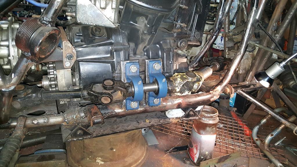 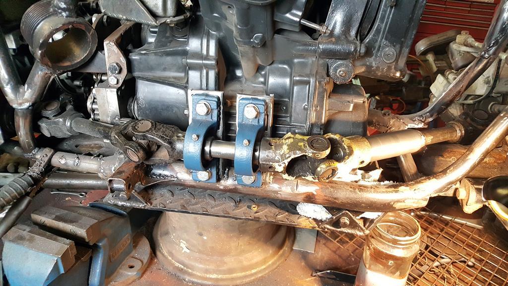 The front er... prop/drive/transfer shaft thingy has been welded up, I will be adding some extra rows of weld "just in case" and to tidy the shaft up a bit. 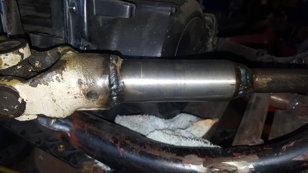 The other end is fitted in place with a tight fitting roll pin. Oh, if your wondering the shaft does look like it's running true :-) 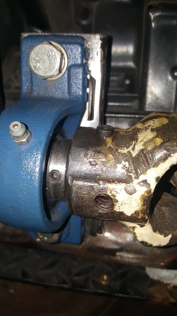 One last thing to do before the drive system is finished... Attach all the sprockets to the shafts.. Starting with the first and second in line there was a bit of lining up work to do.. Here's No 1. 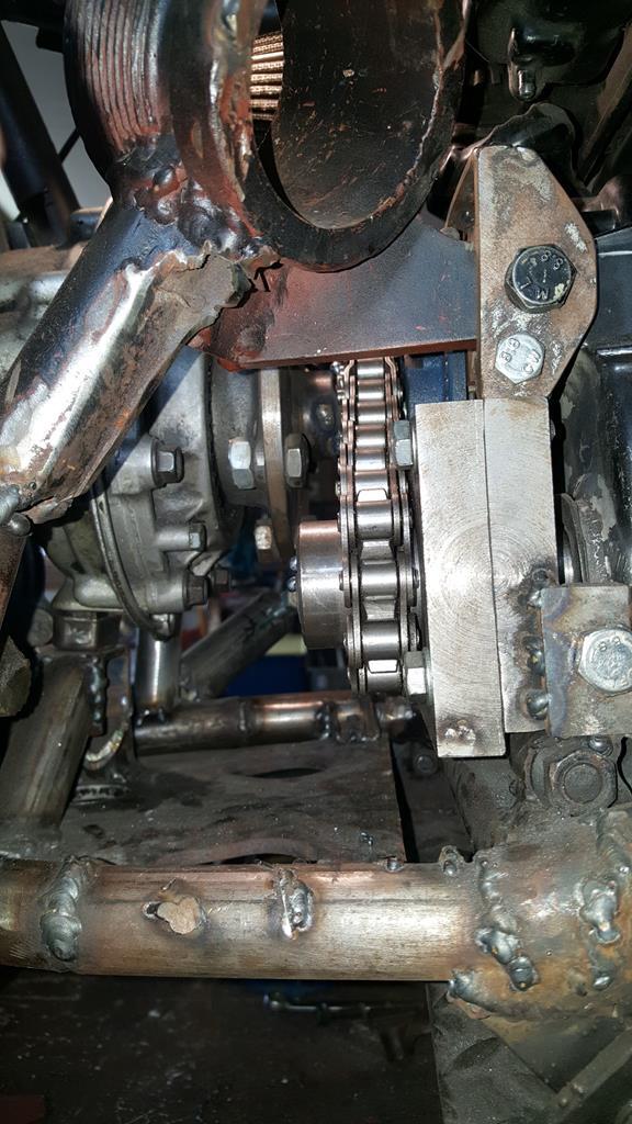 A close up and you can see the chain wants to bend to the right or forwards if you will. A bit of extra space between the chain and bearing holder would also be nice.. 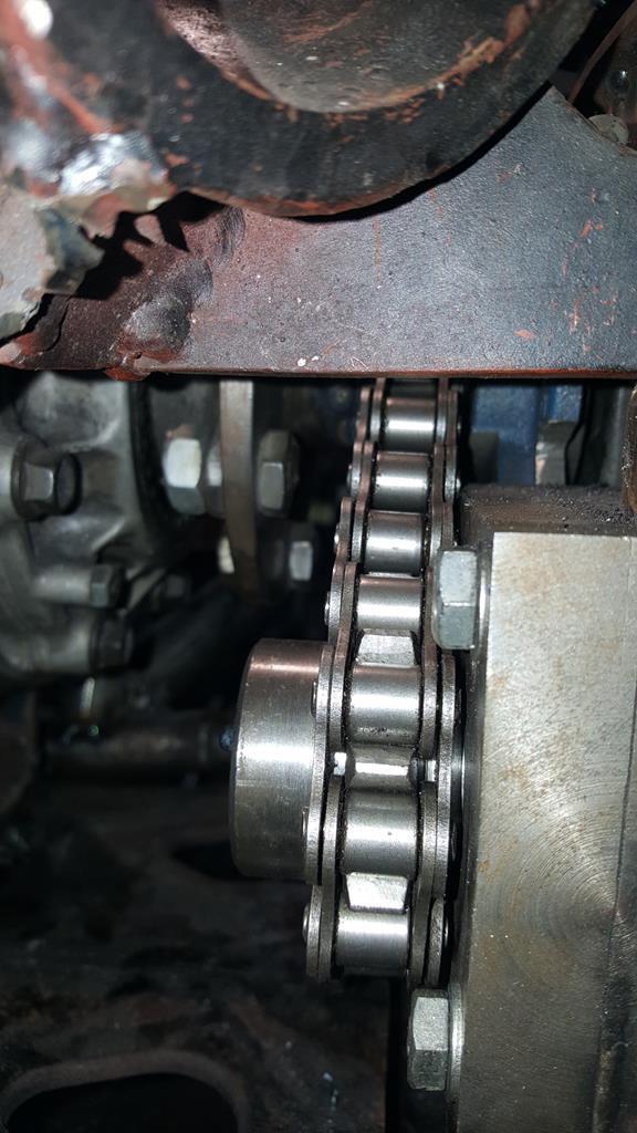 At the other end of that chain things were also a bit tight between the chain and bearing.. 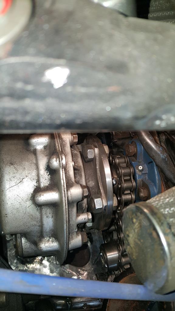 To solve the problem this part came back out for a bit of turning so the sprocket could be moved away from the bearing. 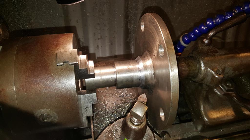 Before welding the sprocket onto the shaft (no space for a roll pin) Rob started toasting all of it.. 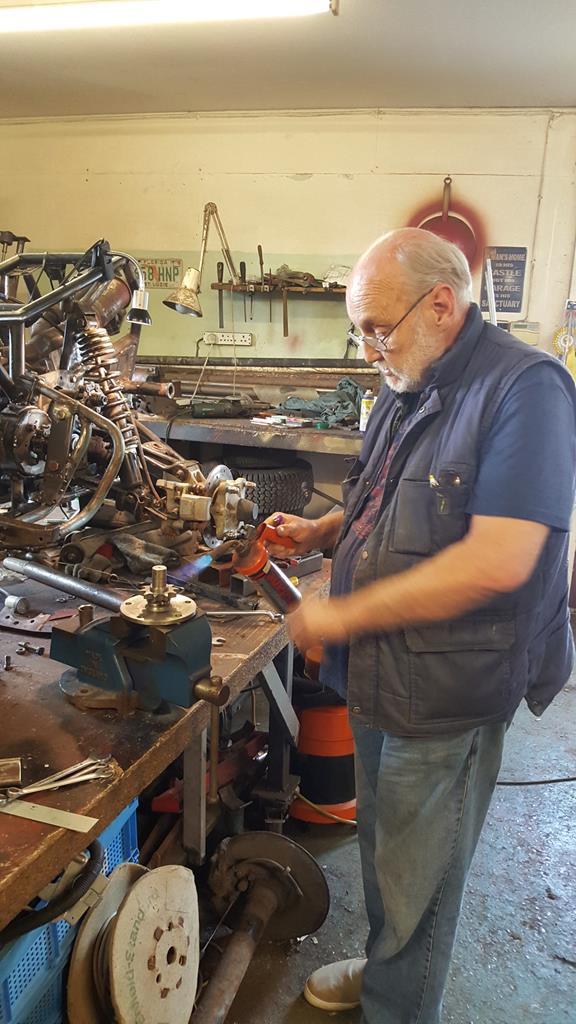 As both the sprocket and shaft thingy were very cold, both were heated up so the cold metal wouldn't just suck the heat out of the weld. 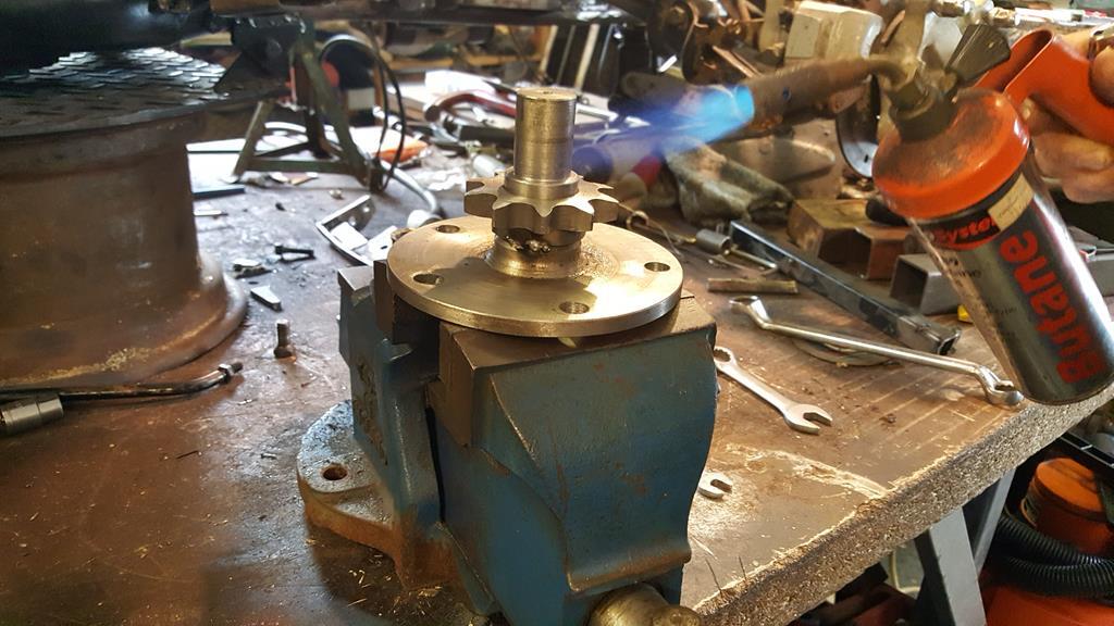 The 90 degree drive thingy out.. A big moment as it means everything will come out of the frame.. Phew lol 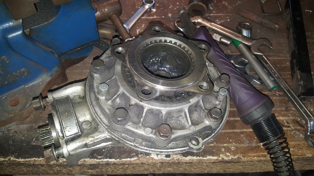 While the drive system was out I was able to do a bit of extra welding inside the frame, as some bit's were only tacked together at this point.. 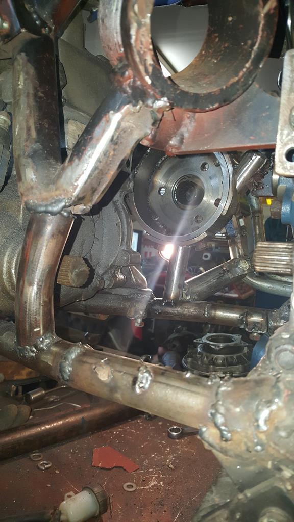 |
| |
My YouTube Channel www.youtube.com/user/UkWheelHorseBlokeQuote - D'you know, it's people like you, doing totally brilliant and pointless stuff like this that gives me a little hope for humanity |
|
|
|
|
Sept 22, 2018 11:38:42 GMT
|
With the above done the time had come to mount the bearing that holds the shaft out of the transfer box up. Here it is roughly in place, the foot rest thingy still needs a little trimming at this point. 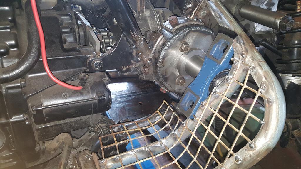 Quite a while back I made this collar/sleave/thingy to hold a shaft in the right place.. Now was the time to tack weld it on. 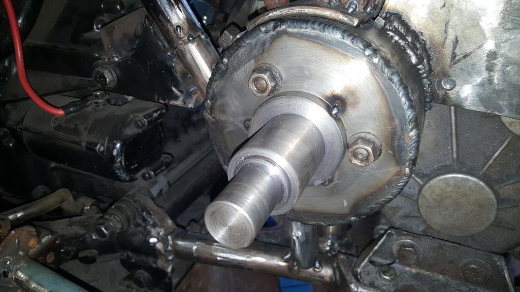 The old steel mesh was removed from the foot rest (I have some new mesh which matches the exhaust guard) and a nice strong bearing mounting plate welded on. Oh, the top tube has also been sliced off and welded back on with a nice strong steel bar inside for extra strength. 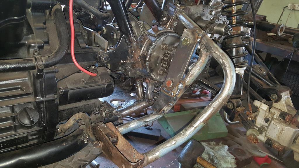 A view from the back, I need to get a half link to shorten the chain and make a tensioner thingy. 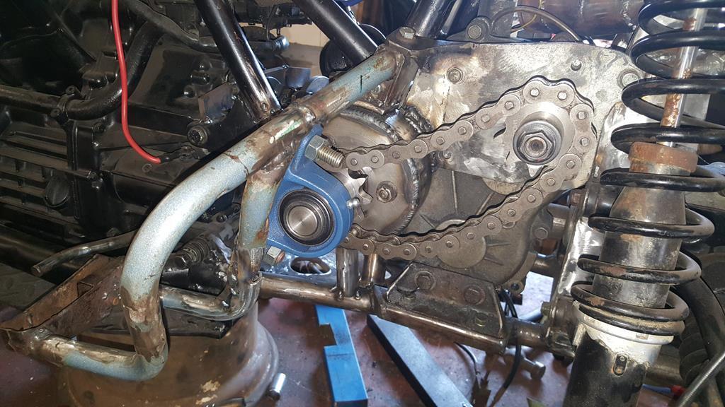 One thing I was worried about was how much the chain would stick through the footrest... As you can see it doesn't stick though at all.. Me happy with that 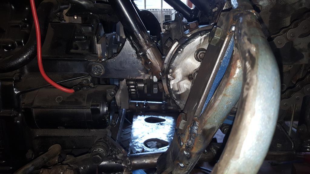 Jumpimg back to the O/S the rear brake pedal mount has been made. Quite a hard thing to photo if you don't have a clear different colour background! 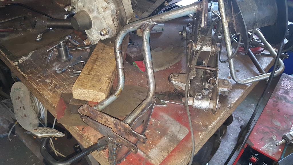 I have fitted the Quadzilla brake pedal, the mount was originally a flat plate that was bolted to all sorts of places to give it strength. 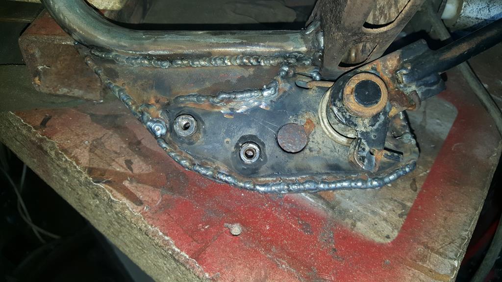 As I couldn't do that I had to box it in. Here's the other side. 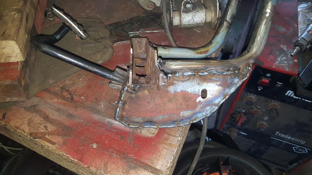 Brake cylinder bolted on. 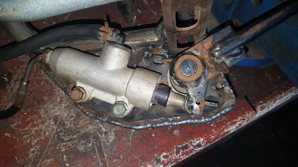 The whole footrest/brake pedal mount thingy bolted back on. The rubber hose to the reservoir will sit just under the steel mesh when it's put back on. The pedal looks like it's lying almost flat, but it's in the right place if you pivot your foot on the end of the footrest which is where your feet naturally fall 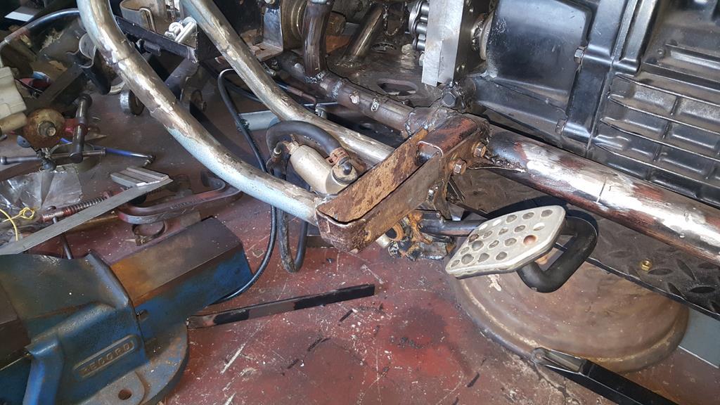 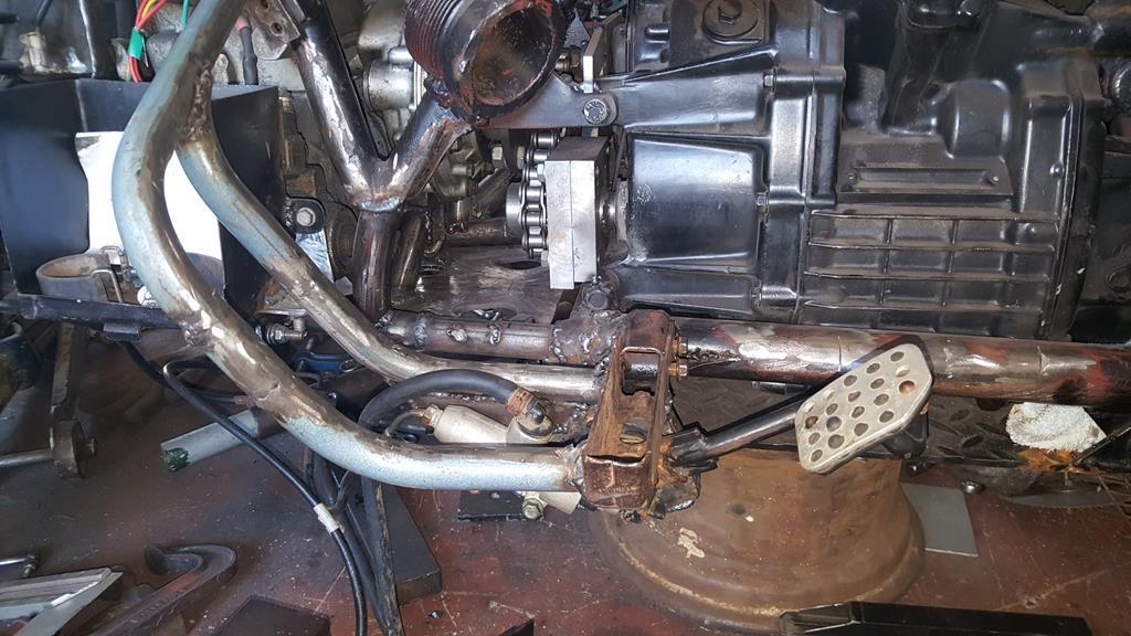 I will make a shield that uses the cylinder bolts to add so side protection to the cylinder.. 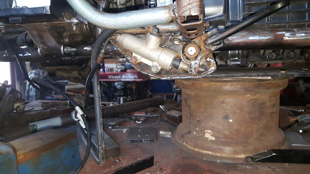 Starting to look a bit busy with the exhaust and driveshaft plonked in place, the propshaft guard will take up a bit more space as well. 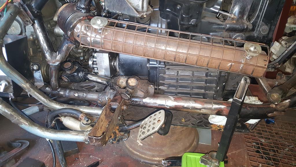 |
| |
My YouTube Channel www.youtube.com/user/UkWheelHorseBlokeQuote - D'you know, it's people like you, doing totally brilliant and pointless stuff like this that gives me a little hope for humanity |
|
|
|
|
Sept 22, 2018 11:18:36 GMT
|
As much as I would of liked to weld the big pipe into the frame to make it all very strong, I wouldn't of been able to get the transfer box out if I did! So I have made up some curved mounts which you will see a bit later.. But while I was at it I thought it maight be an idea to bolt a few bits in place to check everything still fitted.. 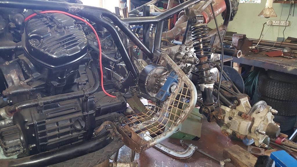 With a bit of trimming and a lot of strengthening the bearing block can be made to fit flush on to the n/s foot rest which keeps things neat and tidy, but the footrest will need a lot of extra strength added. 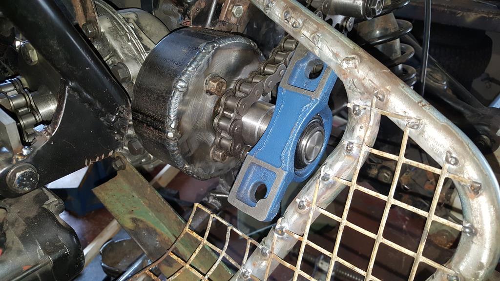 I did at one point think I would have to widen the foot rests as the chain, sprocket and bearing would take up so much space.. But with the bearing mounted flush the chain and sprocket hardly poke through at all, also the 90 degree mount only takes an inch or so foot space away from a bit of the footrest that doen't feel a natural place to put your foot anyway.. So no widening needed, just a bit of extra mesh to go over the chain.. Oh, I do have some much better looking mesh to replace the rather tatty looking mesh thats fitted already. 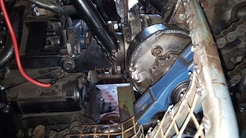 A view of the back.. The chain needs to lose a link and a half and there is plenty of space to put a chain tensioner. 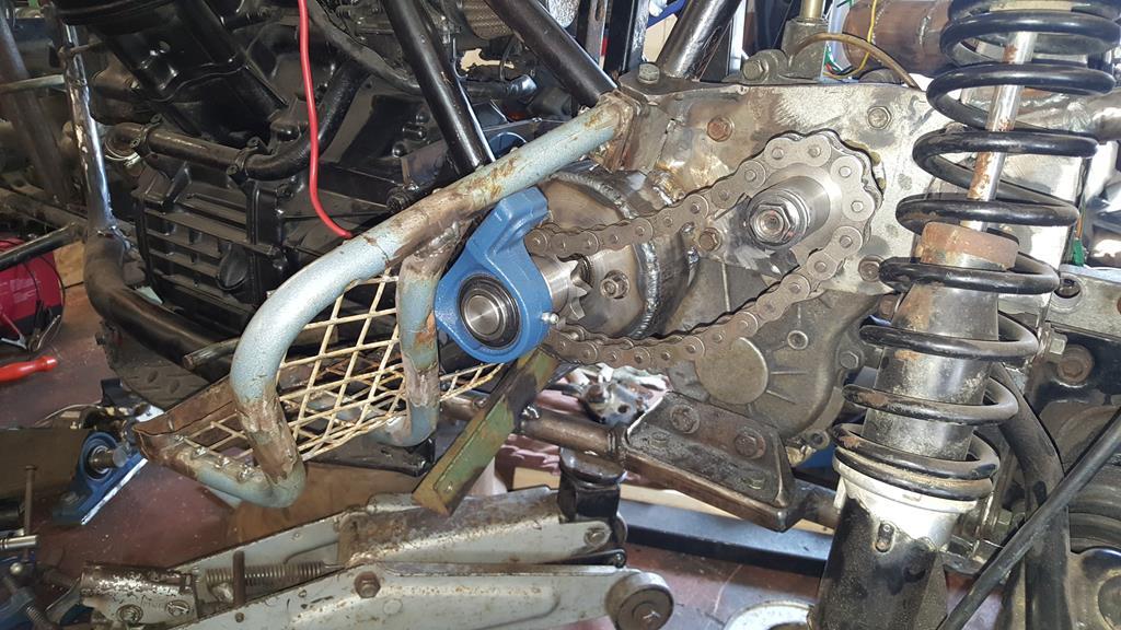 Good news with the o/s footrest as well.. The drive shaft that goes to the front now takes up so little space (much closer to the engine etc) that all I need to do is put a cover over it so it doesn't try and grab my boot laces as it spins.. 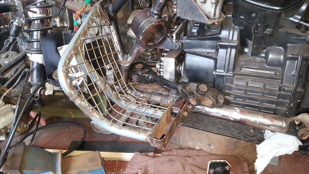 Plenty of space to mount the brake pedal as well 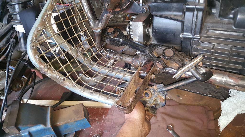 Back around the other side.. Having got the 90 degree drive thing in the right place, it needed to be mounted strongly. The curved brackets were made by welding one end of a thick length of flat steel to the large bit of thick wall pipe and beating it around with a large hammer while it was still hot from welding.. I thought I had some photo's of that stage but I can't find them! As you can see it's all only tacked in place at the mo, it will only get fully welded once I know the transfer box etc can actually be removed from the frame! In theory they should, but you never 100% know for sure until you try.. 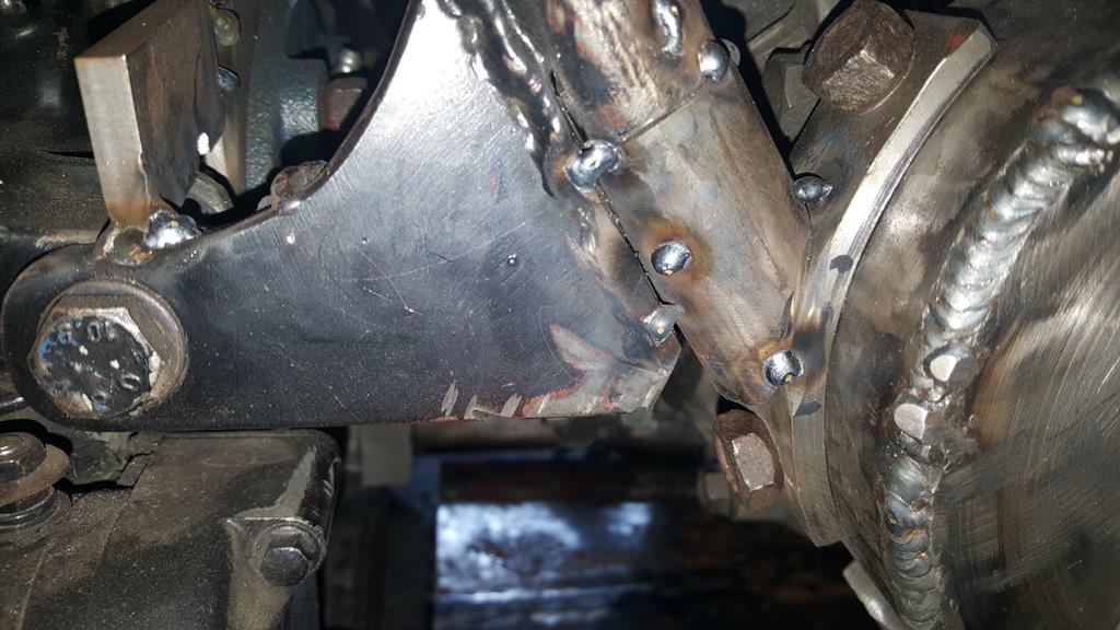 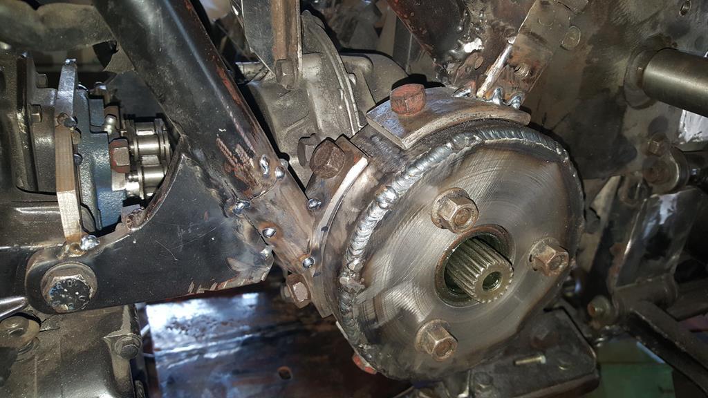 A thrid mount will be going down to the frame but I couldn't work out exactlly where until I had made and mounted a strengthening plate that runs between the frame rails.. Of course I did not have a large enough thick enough bit of steel plate, so I had to make one.. Missing a few photo's here but I had to slice up a Wh 312-8 fuel tank/fender pan mount for the steel.. Clamped down ready for welding. 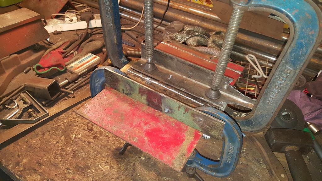 Leaving a big enough gap to fill with weld. 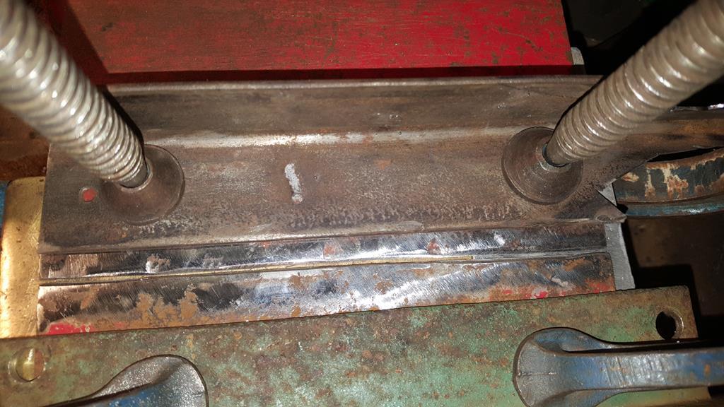 Weld won't stick to brass so a brass plate was clamped to the underside.. The black bit is ally which works as well, it just burns away a lot faster.. 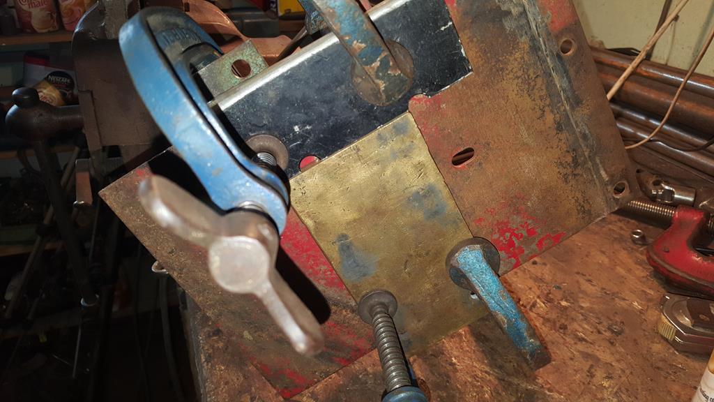 Welded, shaped and roughly put in place. 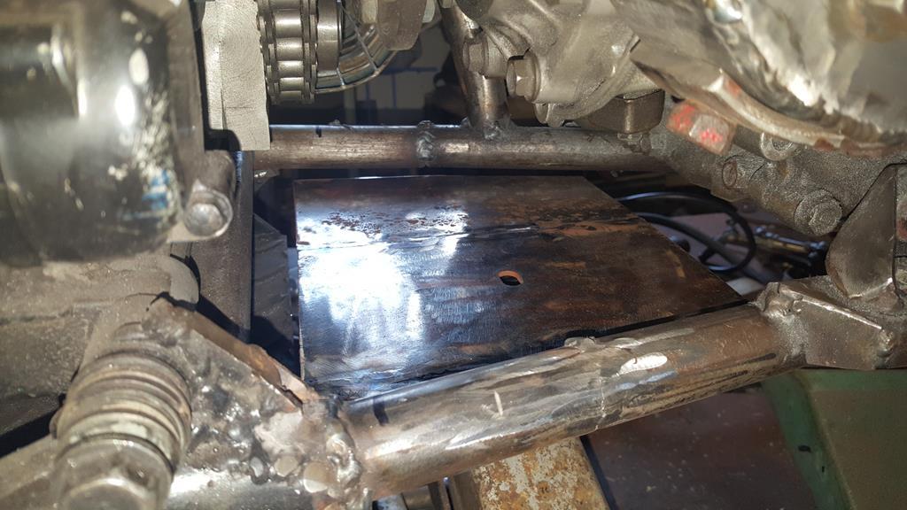 To mount the plate I knocked up four of these captive nut brackets.  In order to center punch the flat plate in the right place for dilling I drilled a hole though a spare bolt that was only just big enough to get my punch in.. It makes sure the punch mark is in the center of the capive nuts. 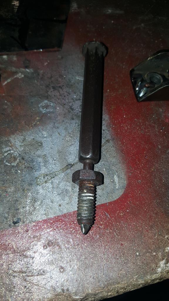 Brackets tacked on.  Lot's of chopping and welding later the plate now has some strengthening holes including one just below the odd shaped tube and bit of box 90 degree drive mount so a ratchet can be used to bolt it on.. 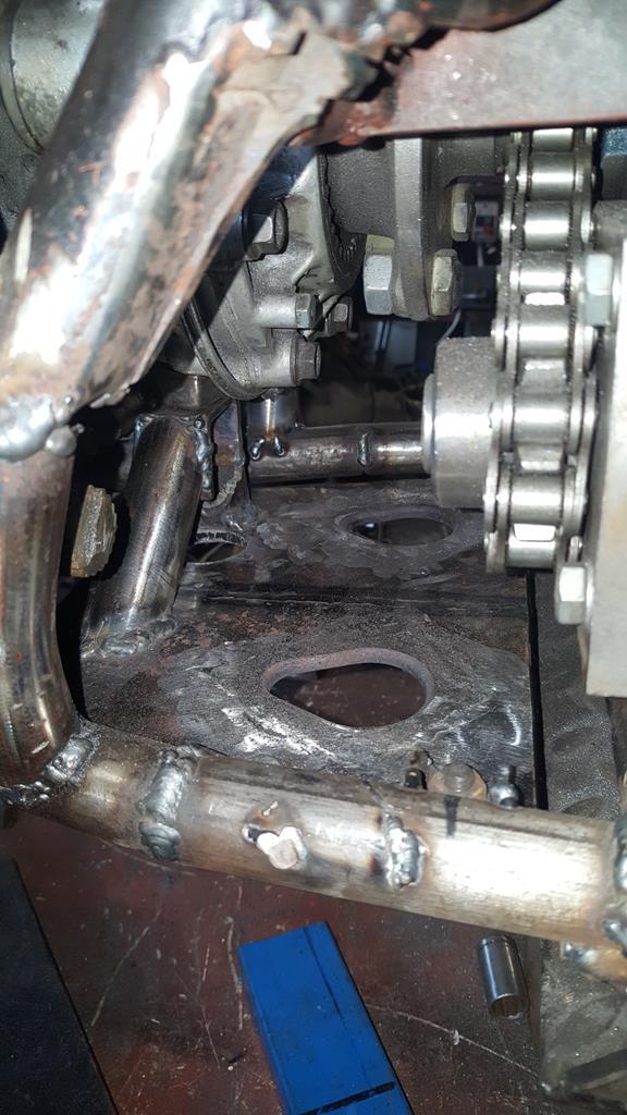 A pic from the other side with the third tube mount tacked in place. 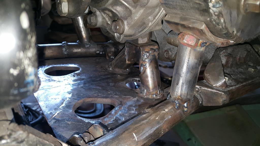 I think now's a good time to drop in a video, anyone for part 23? :-) |
| |
My YouTube Channel www.youtube.com/user/UkWheelHorseBlokeQuote - D'you know, it's people like you, doing totally brilliant and pointless stuff like this that gives me a little hope for humanity |
|
|
|
|
Sept 22, 2018 11:00:40 GMT
|
Very much so... Thanks George :-) Well, long time no update. Sorry about that. It's been a very very busy summer that has not really given me any spare time to do anything including forums and even YouTube! So what has been happening at the workshop has been happening at a slow pace, I have been taking photo's and videoing the action, up until a week or so ago I've not had any time to do anything with the footage! Sooooo... starting where we left off, the shaft that goes on to the side of the transfer box.. Here it is after welding on the splined part, turning the welds down, and a turned down bit to fit a bearing. 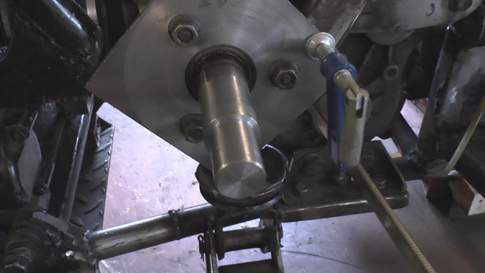 But how to hold it in the right place for making bearing mountings as we all know splines always have a bit of play in them? This will do the job 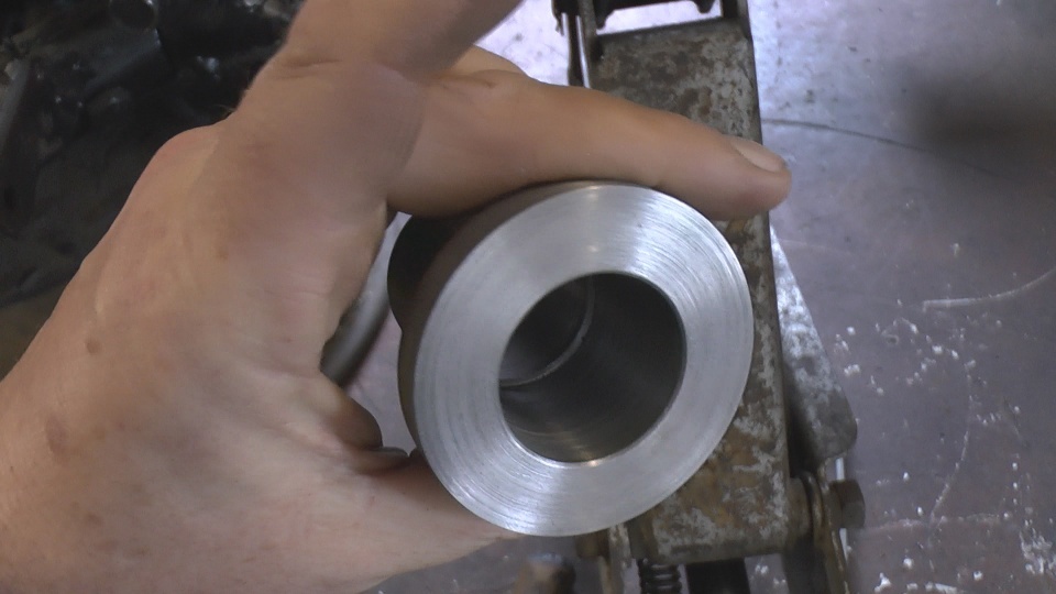 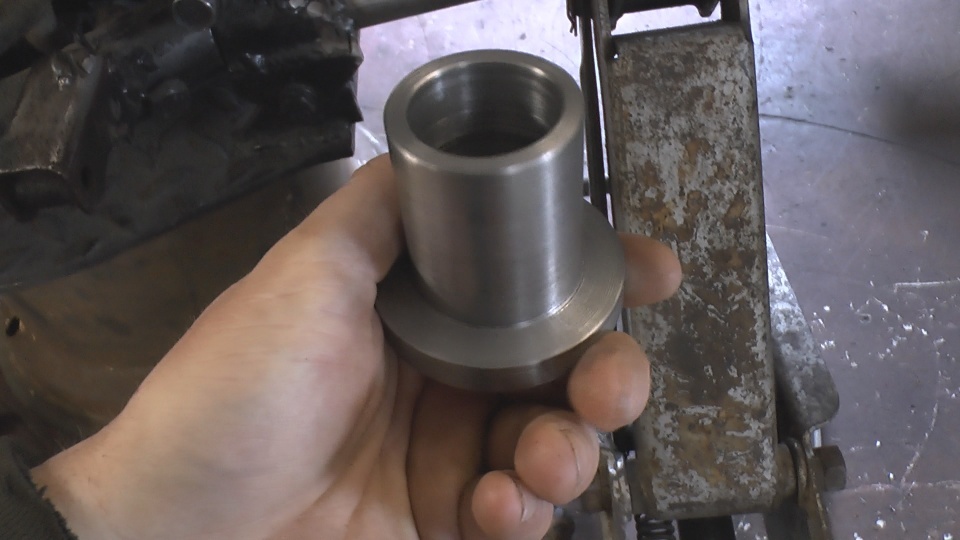 Slide over the shaft.. Once it is tack welded to the flat plate behind it will hold the shaft steady and put it in the right place to make a mount for the bearing that goes on the end... I hope that makes sense? 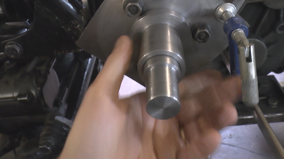 Now another fun bit.. A long long time was spent getting the 90 degree drive in exactly the right place.. No mean feat considering it had to be right in so many planes! To make sure it stayed put, the tempoary mountings (bit of angle) were temporarily tacked in place.. 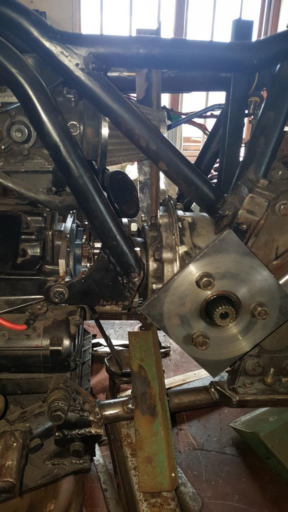 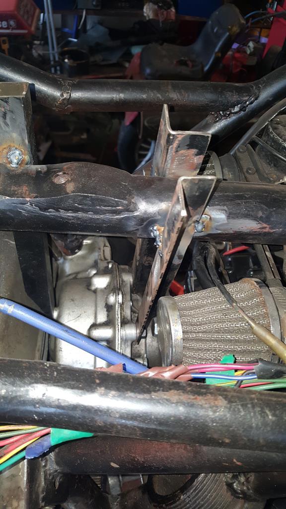 In the last above photo you can see the square bit of plate bolted to the end of the 90 degree drive thingy... Well, it didn't stay square for long.. Ok, it's not perfectly round, but that's not a problem as you will see. 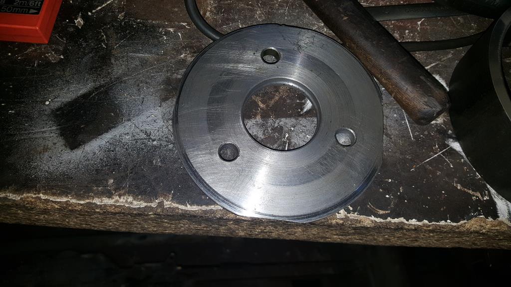 But what to fit it in?? A bit of this 5 1/2 diameter pipe will do Yes I know it doesn't look that safe, but due to the weight of it, it wasn't going anywhere.. 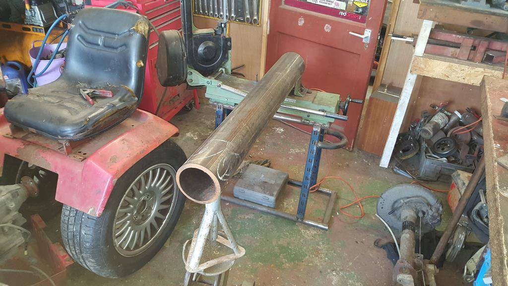 A 2 inch length of pipe with both sides faced off on the lathe. 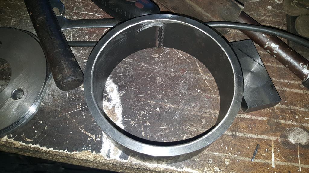 The lip I turned on the round plate makes it a perfect fit in the bit of pipe. 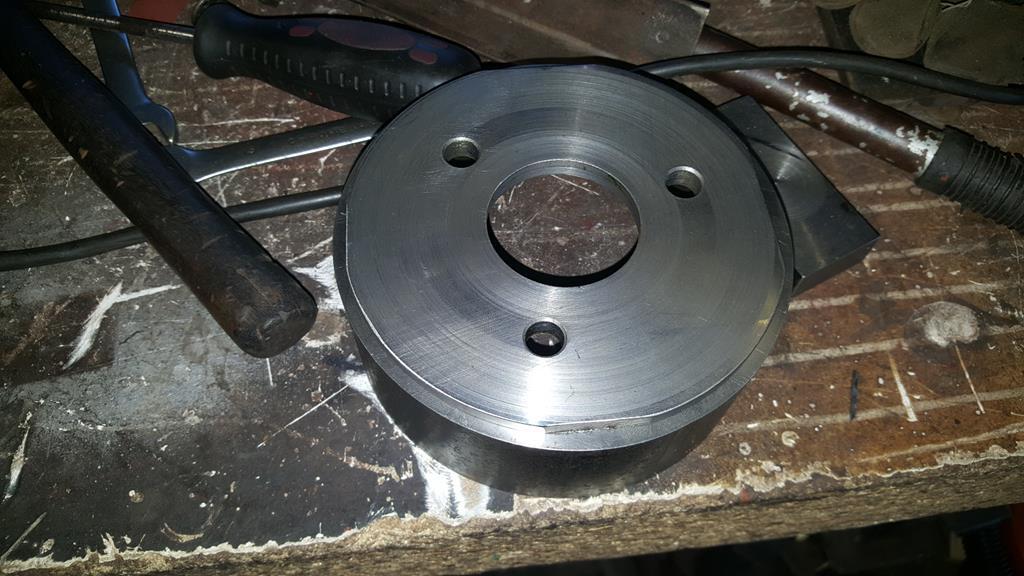 Plonked on to have a look.. 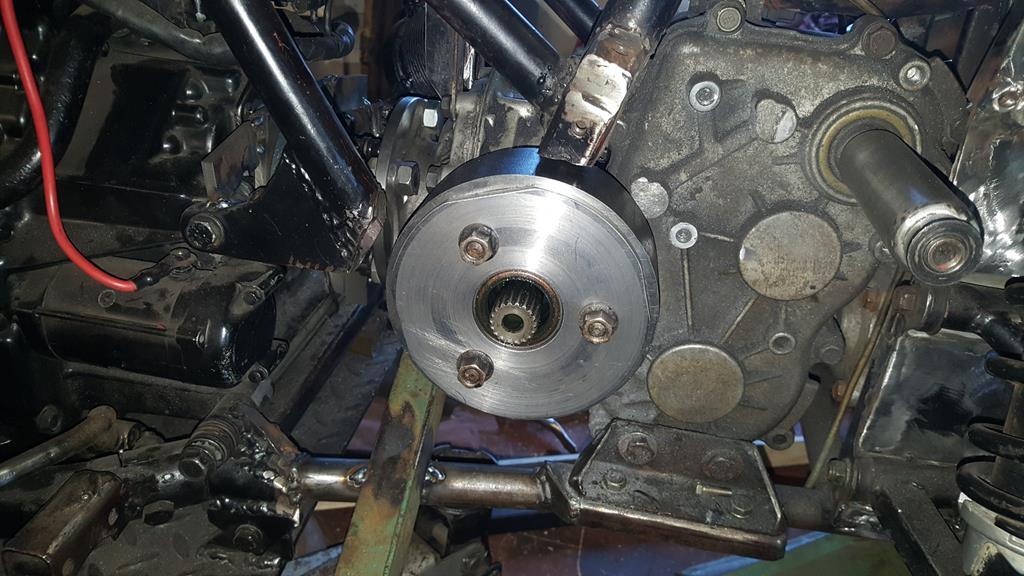 A lot of welding later including 3 long runs inside and I don't think the plate and pipe will be parting company anytime soon 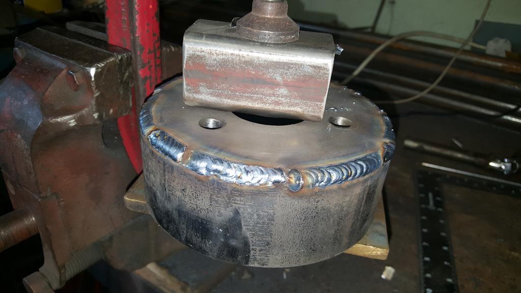 |
| |
My YouTube Channel www.youtube.com/user/UkWheelHorseBlokeQuote - D'you know, it's people like you, doing totally brilliant and pointless stuff like this that gives me a little hope for humanity |
|
|
|
|
|
|
Aug 22, 2018 17:34:26 GMT
|
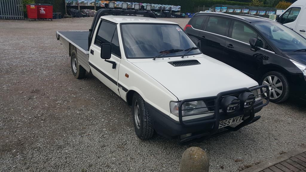
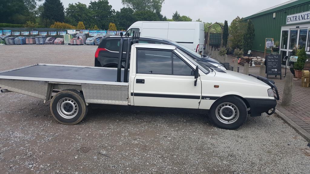
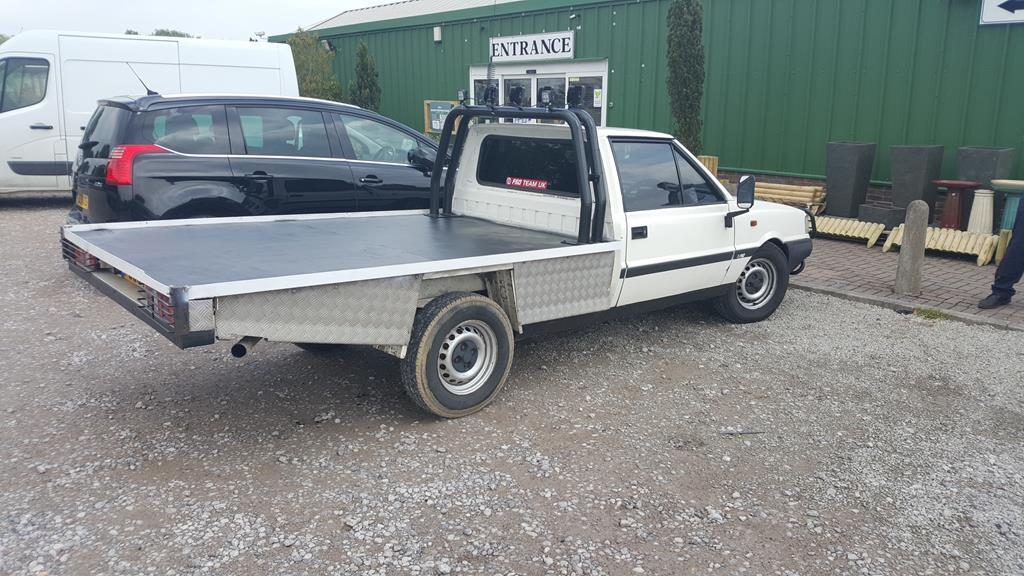
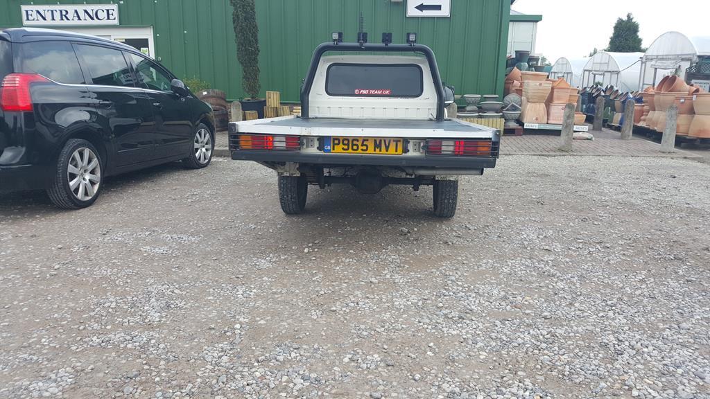
This beauty was spotted the other day.. I got a driving ban in one of these when I was a lot younger and more foolish.. Seeing one again made me all nostalgic, in a smiling, shaking my head at my foolish years kinda way. 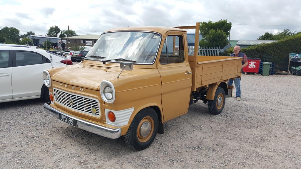 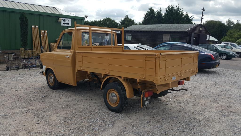 |
| |
My YouTube Channel www.youtube.com/user/UkWheelHorseBlokeQuote - D'you know, it's people like you, doing totally brilliant and pointless stuff like this that gives me a little hope for humanity |
|
|
|
|
Aug 22, 2018 17:25:45 GMT
|
|
Hi all, I have asked if I know of anywhere/anyone in Kent who could value a 1958 Standard 10.
The problem is even though the car is in good condition and has been dry stored it does not start.. I have no idea why not..
Sooooo, does anyone know of valuers in Kent who would come out to give a valuation on the Standard, which is in Ashfrod by the way..
Thanks in advance Guy's n Girls
|
| |
My YouTube Channel www.youtube.com/user/UkWheelHorseBlokeQuote - D'you know, it's people like you, doing totally brilliant and pointless stuff like this that gives me a little hope for humanity |
|
|
|
|
Jun 20, 2018 10:46:31 GMT
|
A couple more spots from Hawkhurst, first this rather nice daily driven AC 2 Litre. I had a quick chat with the owner, it would seem that the original engine died in a rather nasty way, so faced with a very hefty (eye watering sort of number) bill to have the engine rebuilt, he decided to drop in a Triumph 2.5 6 pot bored out to 2.6 with twin carbys, sorted head, lightened flywheel and the Triumph overdrive gear box. 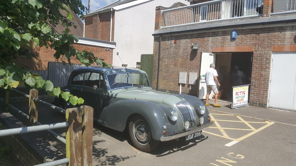 And 20 secs walk away was this beauty.. 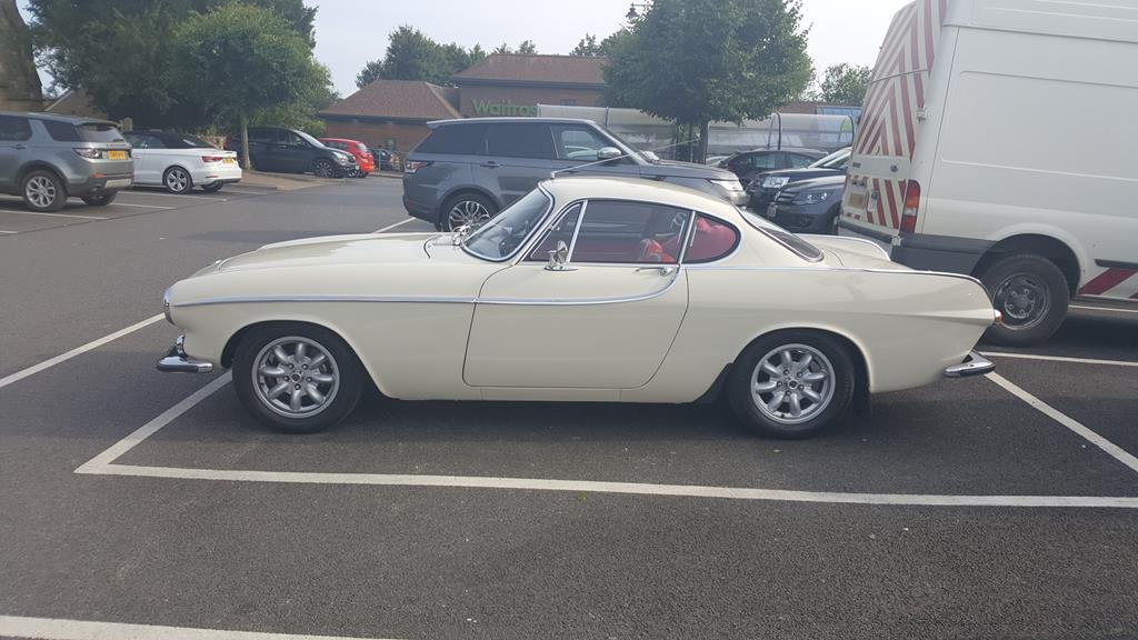 |
| |
My YouTube Channel www.youtube.com/user/UkWheelHorseBlokeQuote - D'you know, it's people like you, doing totally brilliant and pointless stuff like this that gives me a little hope for humanity |
|
|
|
|
Jun 20, 2018 10:35:29 GMT
|
The Volvo now looks like this and is ready for the "metal monkeys" (as I call them) to come and collect. Now I'm sure there are a few of you who are wondering why I'm pulling a perfectly good car apart, and I can understand your thinking.. However.. The poor 940 isn't as good as it looks.. The poor thing had already spent at least 6 months parked up.. For the next MOT it would of needed 2 new tyres, a new exhaust, new brakes on the rear as they are totally shot, welding on both innner wings, various pipes that are falling apart.. That's just things I noticed while pulling it apart.. The previous owner had got another car and didn't have the ££'s to get the 940 sorted.. I guess eventually the poor Volvo would of ended up down the scrap yard, so at least this way I'm giving parts of it a second chance at life As much as I like the idea of smoking around in a big wagon, the insurance and fuel costs would cripple me! Anyway, the said photo. 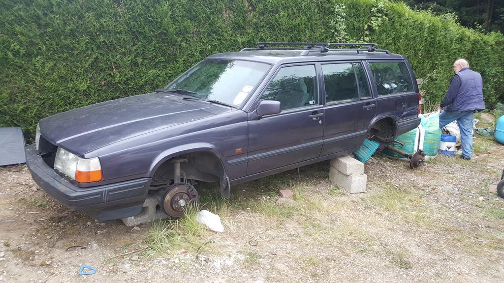 Parts removed.. Engine, trans, wiring loom... Propshaft. (may need shortening quite a bit ) 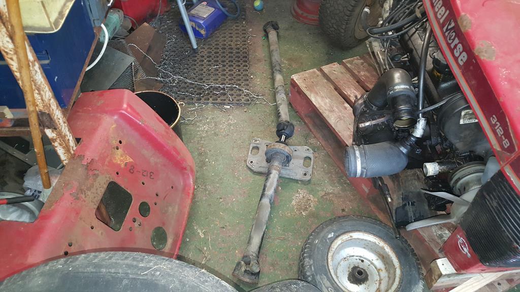 Four wheels to smoke the tyres/tires off of 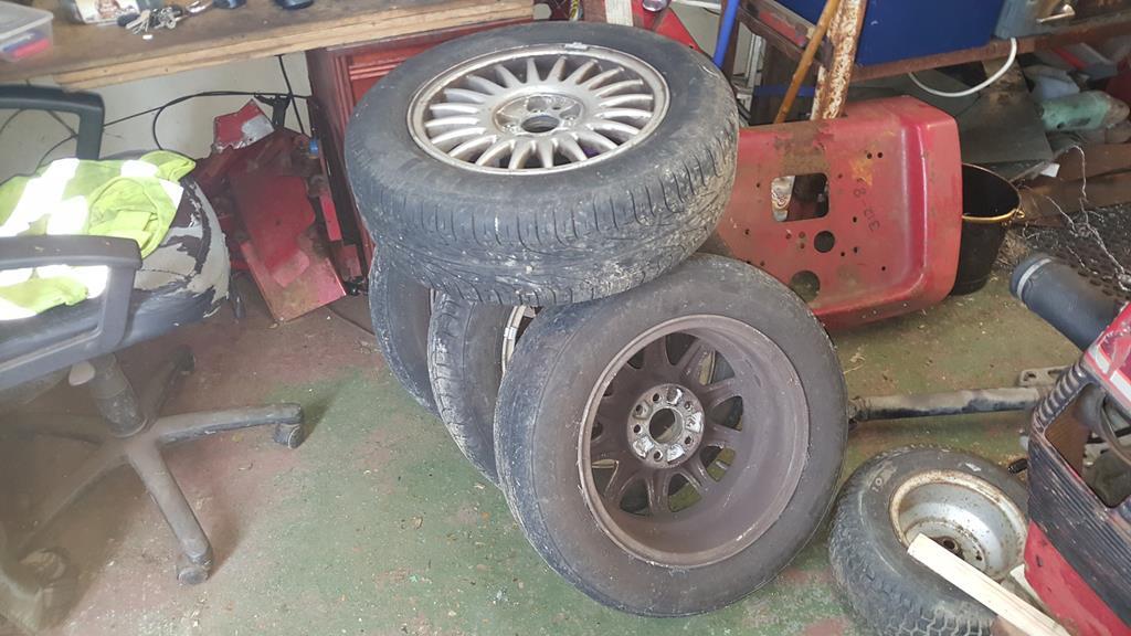 Rear axle.. (I may need to narrow this a bit ) 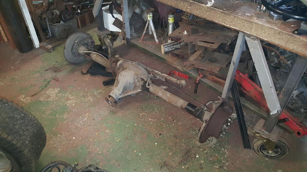 And a new bit of wall decoration  To keep Nigel happy, here's a pic of him actually driving the forklift as the engine was moved from a pallet to a four wheel'd trolly thingy. 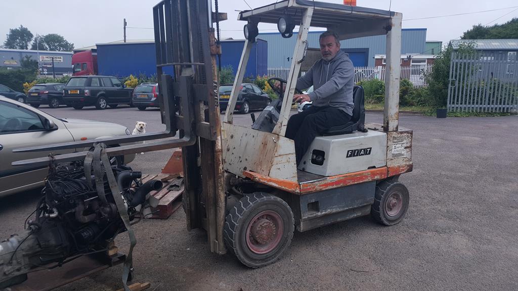 Though I think the forklift fumes may of gone to his head a bit 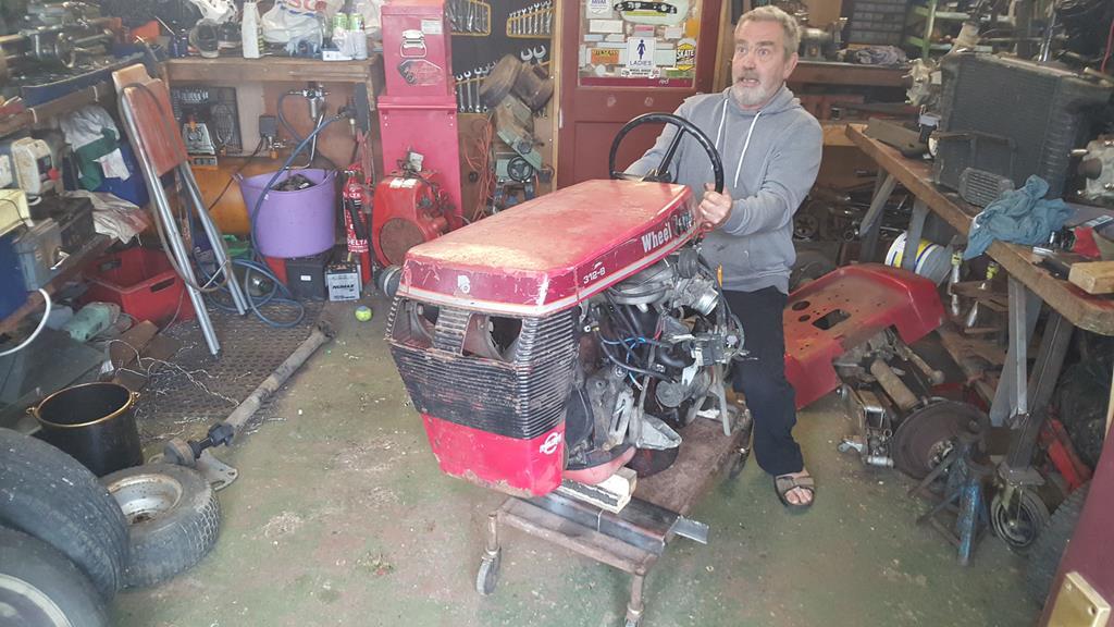 With the pallet out the way we could plonk parts in more or less the right place.. For the comedy value the wheels were put where they would be on a standard WH... A bit narrow me thinks 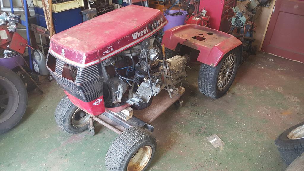 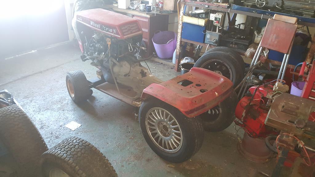 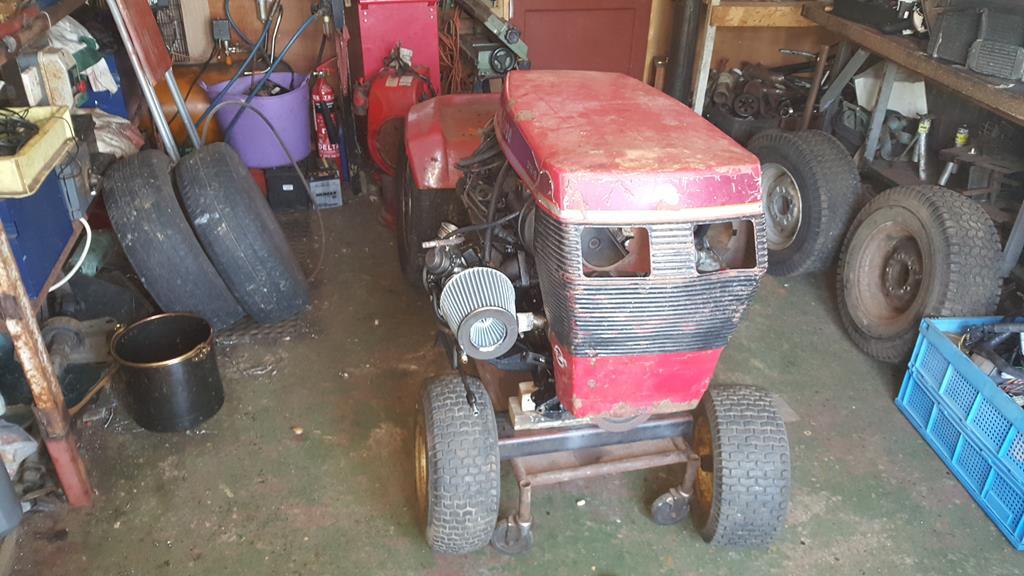 I like this view, with the wonky wheels and panels it kinda looks like a wacky cartoon 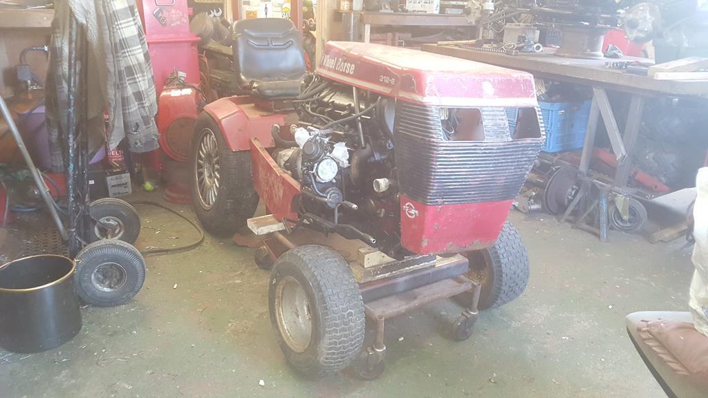 I'm trying to be good and get MadTrax finished before I start on this build, but you just know I have to have a fiddle and make a start even if it's only getting everything in the right place so I can take some measurements.. A lot to work out first before I can even think about making a chassis! And to finish this update, have another video.. Wheel-Vo part 2. Sorry about the rubbish sound quality |
| |
My YouTube Channel www.youtube.com/user/UkWheelHorseBlokeQuote - D'you know, it's people like you, doing totally brilliant and pointless stuff like this that gives me a little hope for humanity |
|
|
|
|
|
|
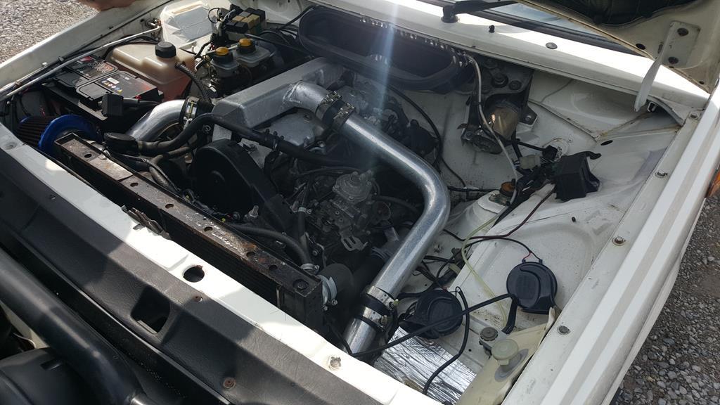
Well this will be all kinds of dangerous and awesome! Can't wait for progress! Thanks Davey, dangerous and awesome sounds the ideal mix Insane ... but in a good way. Thanks Opti, I guess being insane in a good way is one of the better ways to be insane It's been a very busy and heavy few weeks, but when needs must.. The Volvo engine bay now looks like this.. 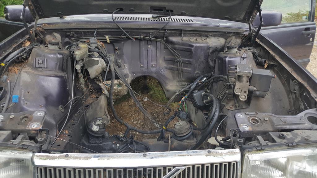 Engine out.. A big thank you to Rob (far right) who has put a lot of time in over the past 7+ days to help me get this stage done. A thank you to Matt (far left) who did the very careful forklift driving to pull the engine and trans out.. And a thank you to Nigel (middle) for offering advice, getting in the way sometimes, and for sitting on the forklift to make it look like he did the driving 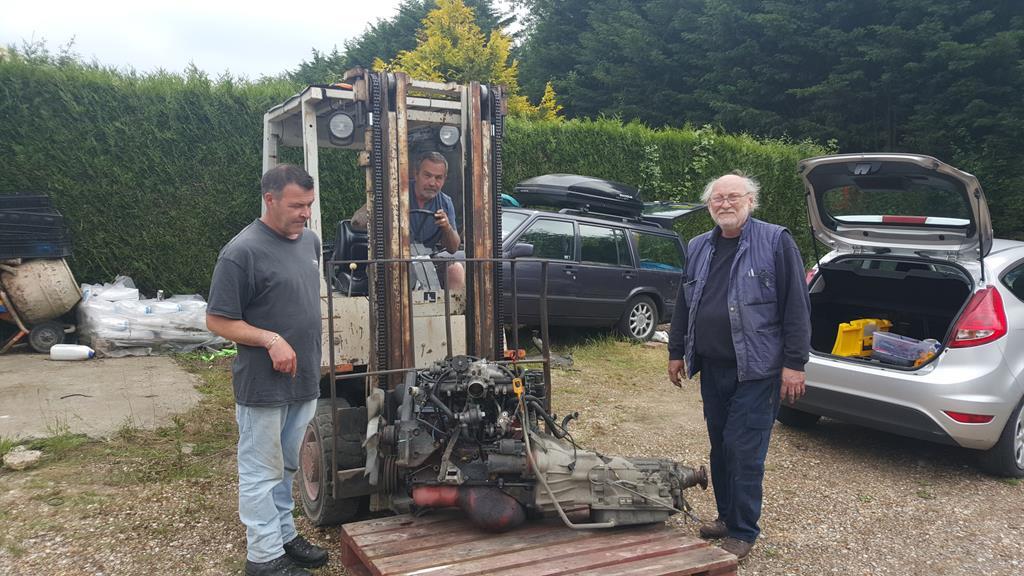 Back in the workshop with a few parts plonked in place.. Only roughly plonked as the pallet is getting in the way and the engine is leaning to one side.... But you get the idea 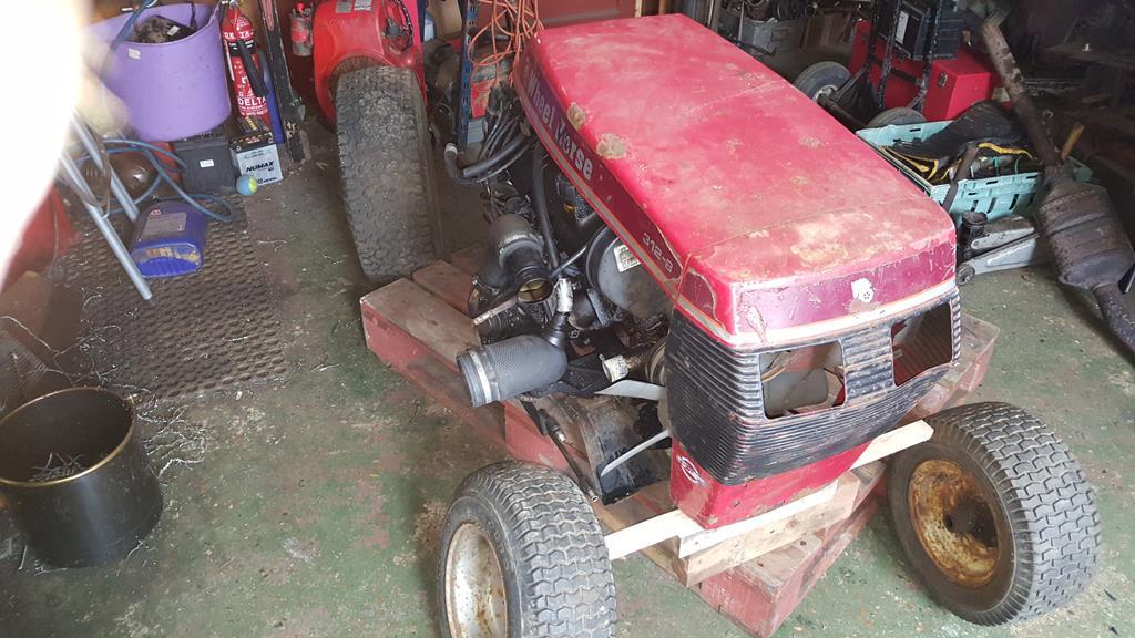 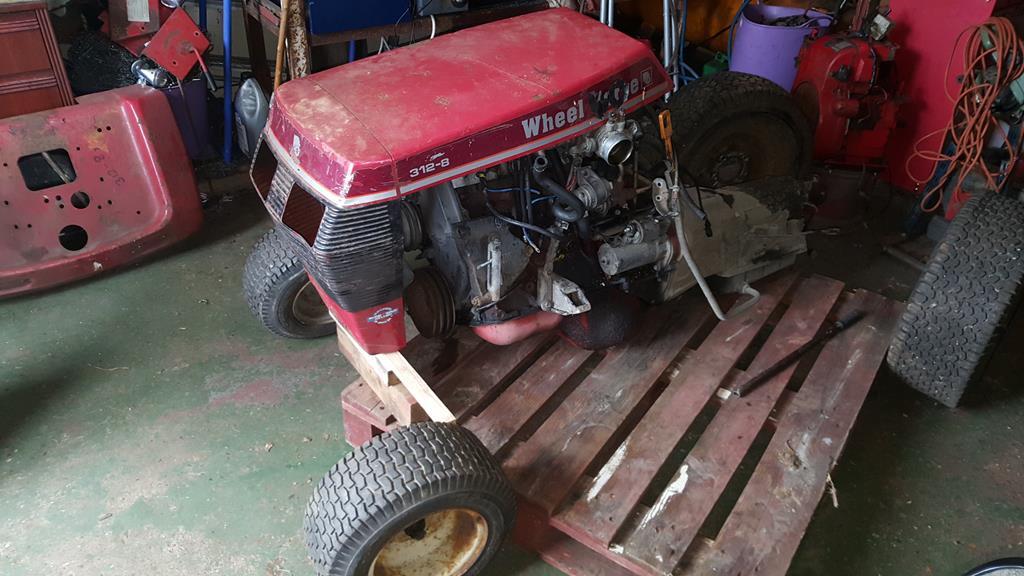 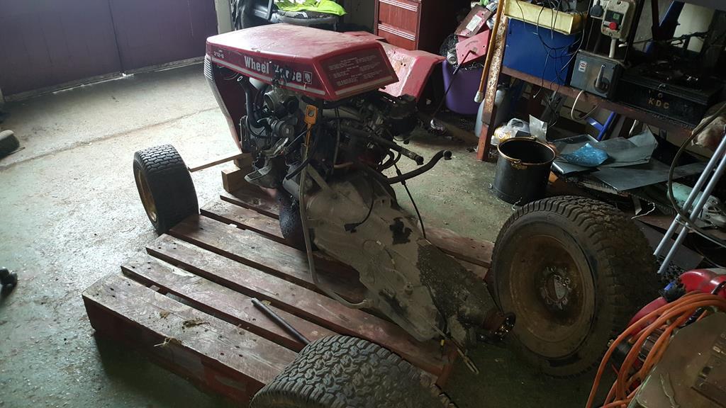 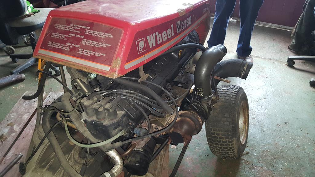 To make the engine run a few wires are needed.... Quite a few as it happens.. I need the complete loom from the engine bay back to the front doors.. Which looked like this once the dash had come out.. 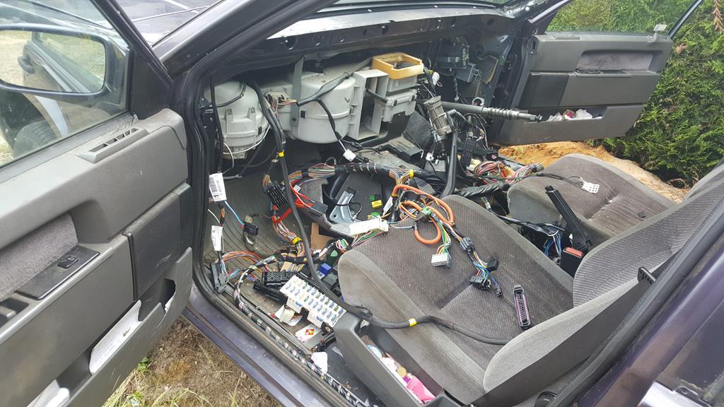 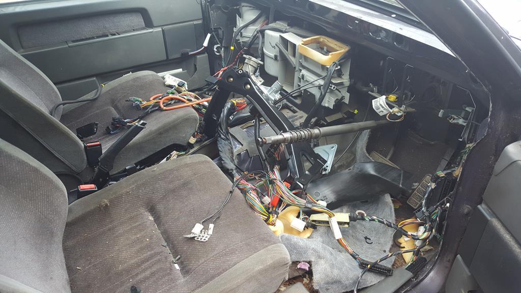 The fuse and relay box! I won't be needing all of them thankfully!. 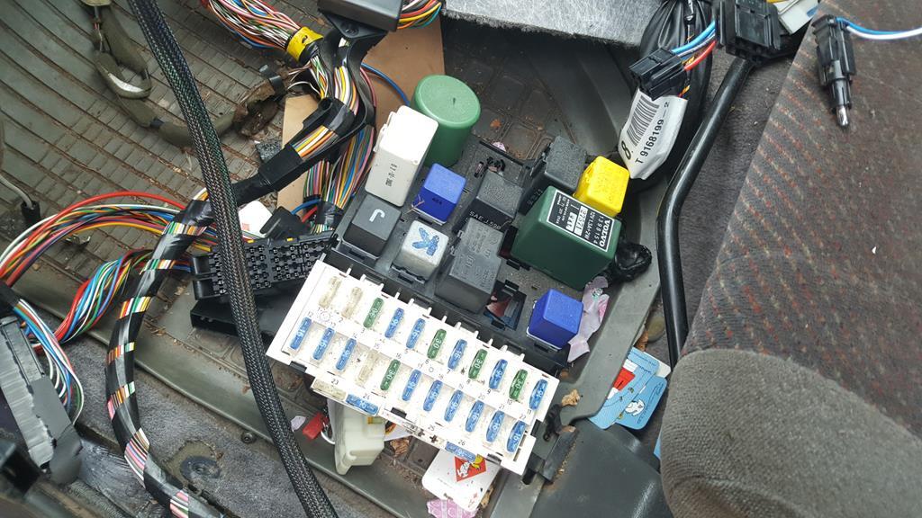 Why so many wires? Well, being a "modern"-ish car I need one of these brains to run the fuel injection system.. 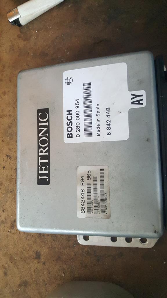 And one of these which is engine management.. I've not opened it up yet to check, I have a feeling (or maybe more of a hope) it's one of the ECU's that can be "chipped" to get the engine producing the power it should be rather than the "tamed back" from the factory as it is now.. Oh, I'm rather new to this computers in car controling engine things, so if I get anything wrong please feel free to set me straight 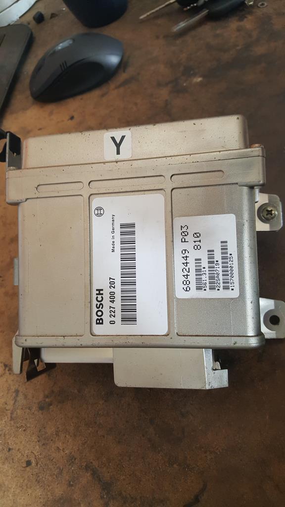 The loom out the car! I won't need about 75% of this as I won't be running power window, rear screen heater, power sunroof or even the headlamp wash/wipers! But I think I'm going to need a very good wiring diagram 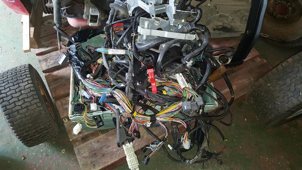 But I do plan to use as many of the guages as I can.. 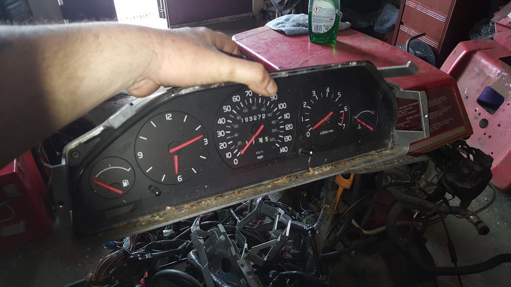 |
| |
My YouTube Channel www.youtube.com/user/UkWheelHorseBlokeQuote - D'you know, it's people like you, doing totally brilliant and pointless stuff like this that gives me a little hope for humanity |
|
|
|
|
|
|
|
|
| |
My YouTube Channel www.youtube.com/user/UkWheelHorseBlokeQuote - D'you know, it's people like you, doing totally brilliant and pointless stuff like this that gives me a little hope for humanity |
|
|
|
|
|
|
I look forward to the outcome. This is the only other wheelhorse I’ve seen photos of before...  I guess the colour caught your eye Well lookie here. Bookmarked, just for fun. Thanks George, fun it's going to be Fantastic, I bought myself a 1967 Bolens Husky 1050 last year for no other reason that it was cheap and local. I've not put it all back together yet and I'm still thinking what to do with it. Hi Hearselover, those Husky 1050's are quite a collectors item these days.. But don't let that stop you doing something mad with it Hasnt Badrep got a spare Volvo engine from his RS200 project? He was going to use it then went back to an MR2 engine iirc. Thanks cochapman, and interesting thought on the engine, but I have found one.. Oh goody - another mad build. Bookmarked, of course! Thanks Morris, a mad build it will certainly be Well Project Wheel-Vo has taken a big step forward this week as the new running gear has been found... You might say it's been safely kept in this big metal box 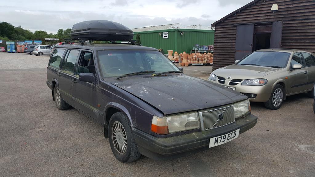 A "can't quite get he's head around my thinking" Nigel gives the Volvo 940 2.3 SE Turbo a thumbs up. 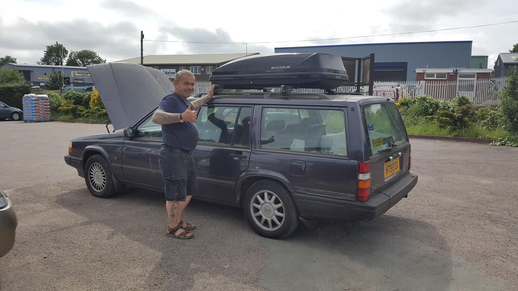 That's quite a big 4 pot! A Volvo B230FK if your into engine numbers. 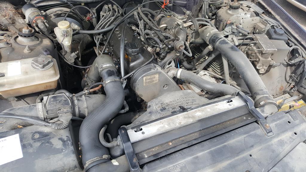 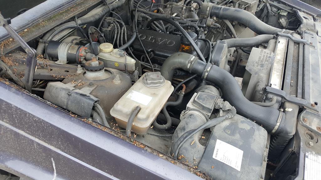 Here's the important bit... The turbo  Size wise a manual gearbox would be smaller, but an auto does make life easier... Also I kinda like the idea of being able to keep both hands on the steering wheel during launch as well 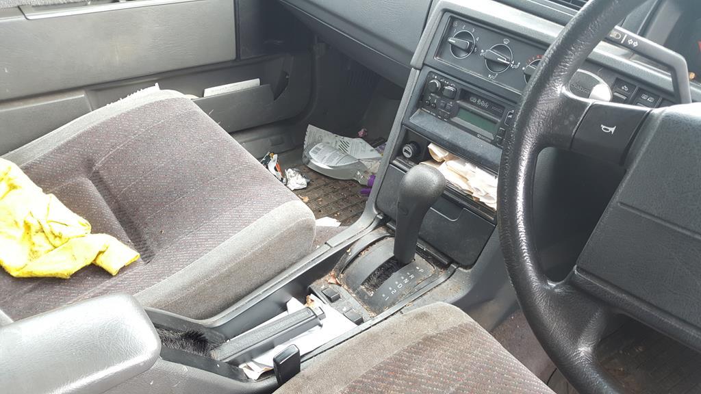 I dug out the WH 312-8 bonnet/hood to have a look size wise...... This pic makes me look totally nuts for even thinking of this project! 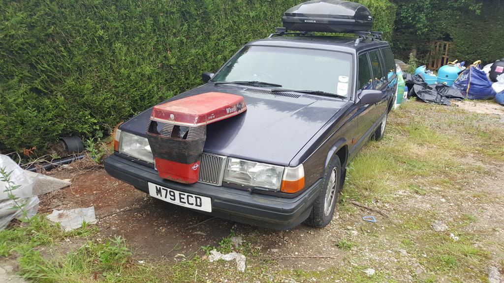 However, lift the bonnet/hood up and plonk the said WH item on and suddenly the engine does not look that big.. A certain amount of errr... "Scaling up" is going to be needed on the WH panels but not as much as I had 1st thought as the actual auto box isn't as long as I had 1st thought. Of course I have to fit a radiator and intercooler under the hood as well. I will be using the Volvo rear axle, they are known to be strong and (quite handy for me) easy to narrow 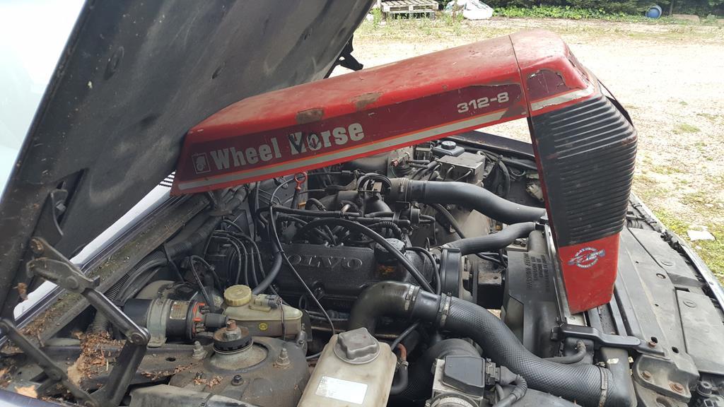 As of yesterday here's where I have got to.. Just need to disconnect the shifter linkage, speedo cable (I think the speedo is driven from the 'box), unplug any electrical bits, unbolt the propshaft, unbolt the 'box crossmember and then the engine and trans can be removed as one.. Glad I have the use of a forklift 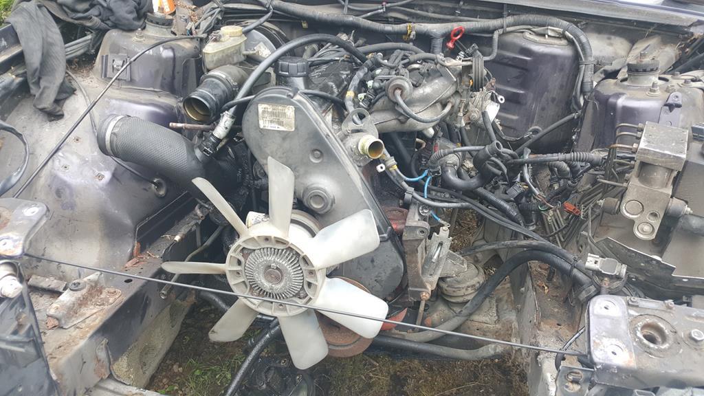 Oh, if anyone needs any Volvo 940 parts that do not make it run and move, message me |
| |
Last Edit: Jun 6, 2018 16:38:31 GMT by Stigian
My YouTube Channel www.youtube.com/user/UkWheelHorseBlokeQuote - D'you know, it's people like you, doing totally brilliant and pointless stuff like this that gives me a little hope for humanity |
|
|
|
|
May 20, 2018 16:38:20 GMT
|
Here's half the bearing holder and a blank other half. No idea why these photo's won't upload the right way around! 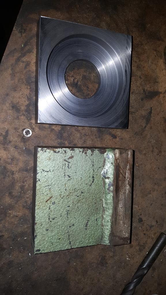 Both sides done. 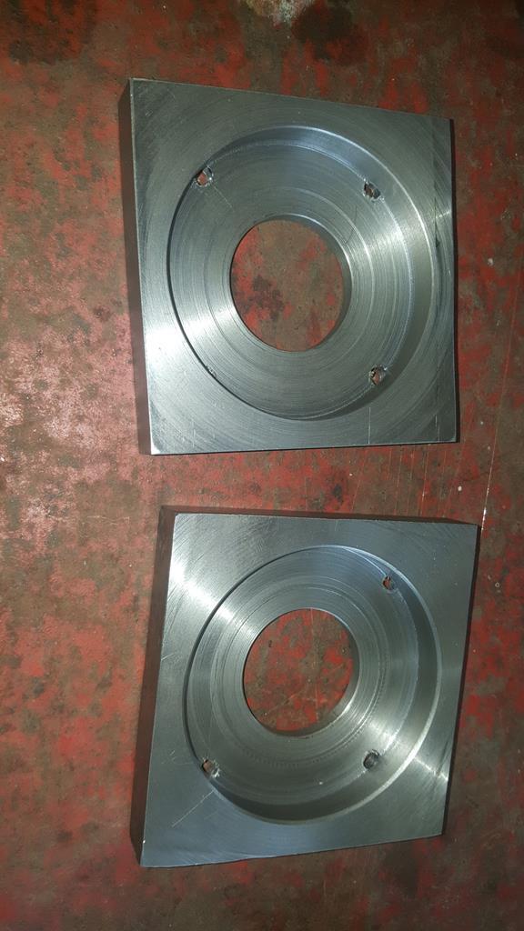 The four holes in each half are there so the bearing can be punched back out the holder should needs be.. 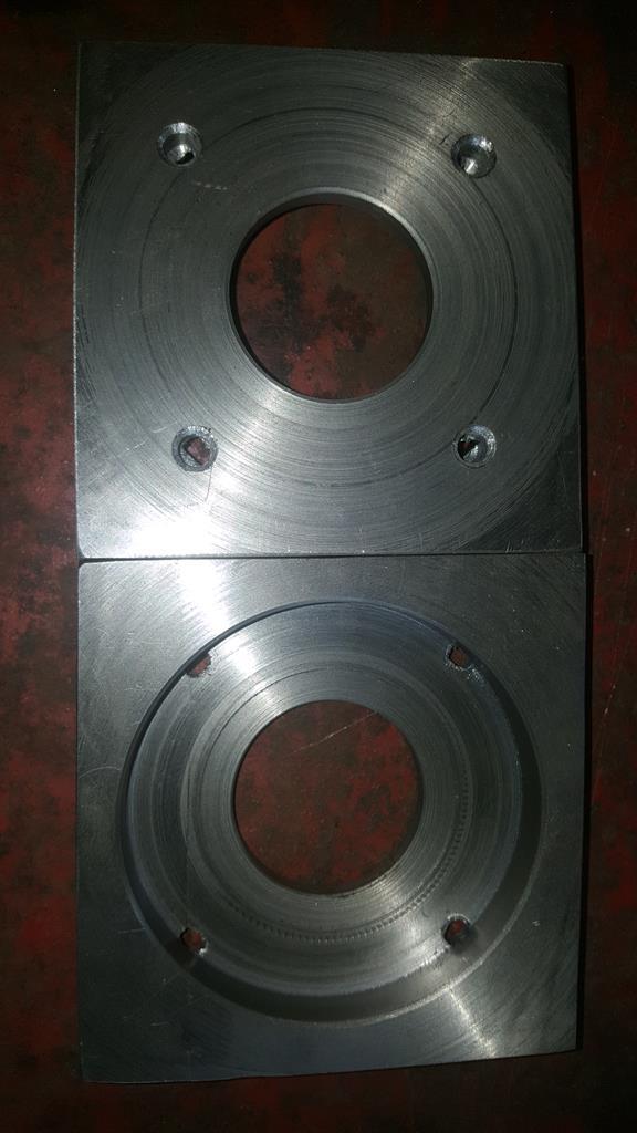 Time to fit the bearing... Almost.. As the holder will have to be taken on and off MadTrax many many times, and a bit of drilling and grinding going on, rather than fit the bearing and risk it getting full of nasty stuff I made.... 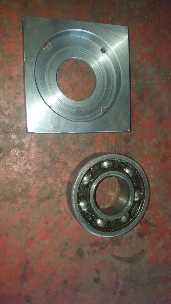 This fake bearing 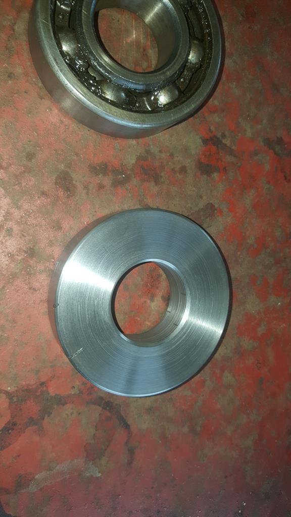 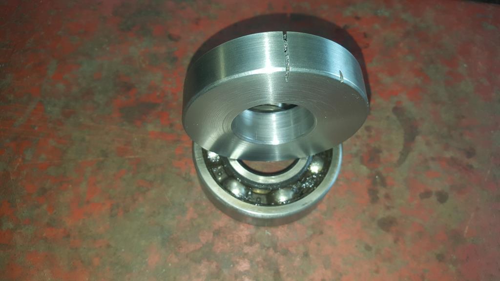 With a little bit of trimming to the inside half of the bearing holder a test fit was in order.. 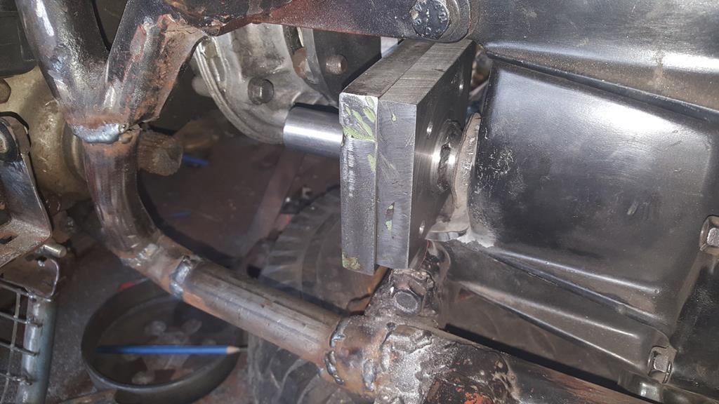 It's rather tight on one of the engine mounts, but it fit's 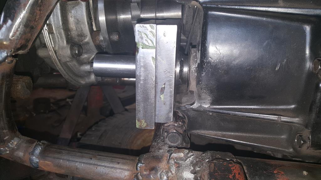 Looks like the sprockets can be made to line up 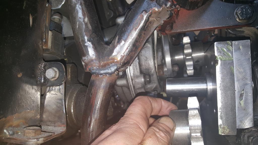 Now the big one... Will the shaft from the transfer box to the front fit without hitting anything and how tight will the UJ angles be? It fit's and the UJ angles are well under 33'degrees, if I remember right the rear UJ angle is about 12'D and the front is a tad over 20.. Much better than it used to be 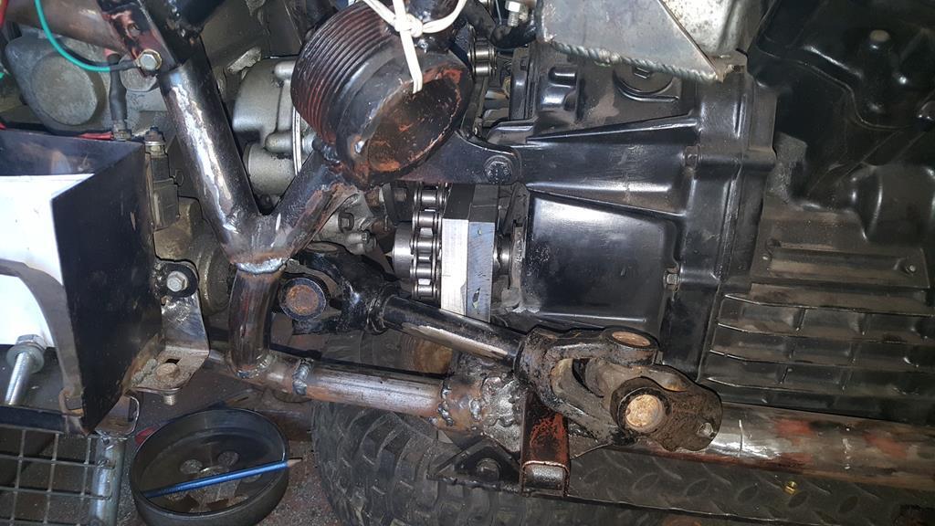 It's tight but there is plenty of clearance 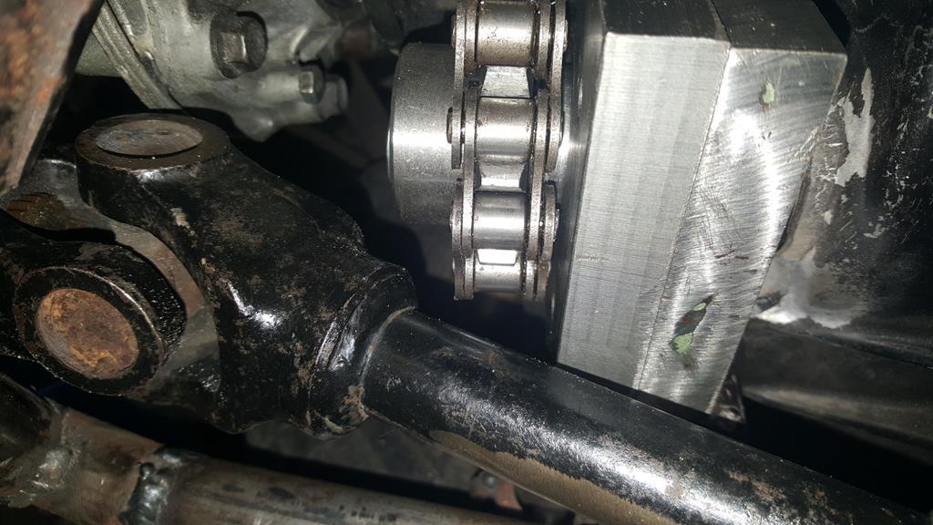 The bearing holder was drilled and a tapped so the two bit's could be bolted together.. A clean up on the lather later and the bearing was pressed in.. I couldn't of been happier with the fit of the bearing 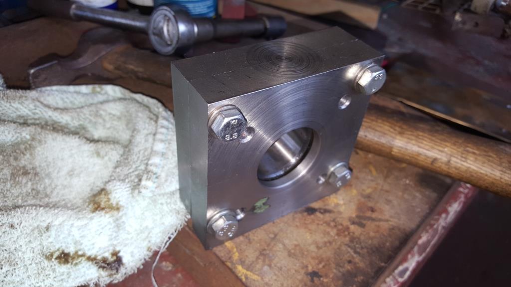 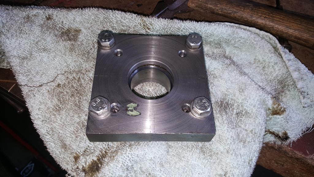 Fitted.. Just out of view behind the holder is a couple of tack welds just to hold the holder in the right place.. and yes the spocket is free to move at the moment as I don't know quite how far up/down the shaft it needs to go. 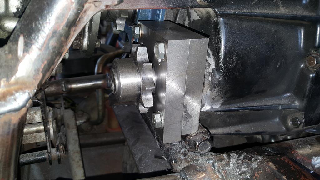 Now onto another the fun part.. Getting the 90'd drive in the right place.. Which is where the bit of angle that is bolted to the drive will come in handy. If you look behind the air filter you can just see 3 more bit's bolted to the drive case.. 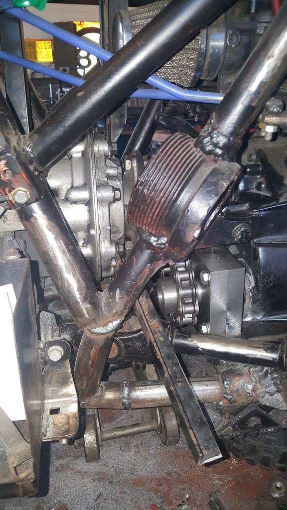 They go up and get clamped to a couple of bit's of box.. This will hold things steady and give me enough adjustment to adjust it's postition. 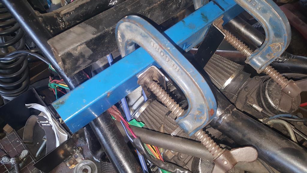 But before I square the drive up I need to make the last bit of the drive puzzle and fit a sprocket and bearing to the hollow shaft that's coming out of the drive.. 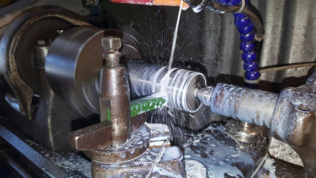 The splined section will be welded on, then the whole thing can be turned down a little on the lathe to fit a sprocket and a pillow bearing. 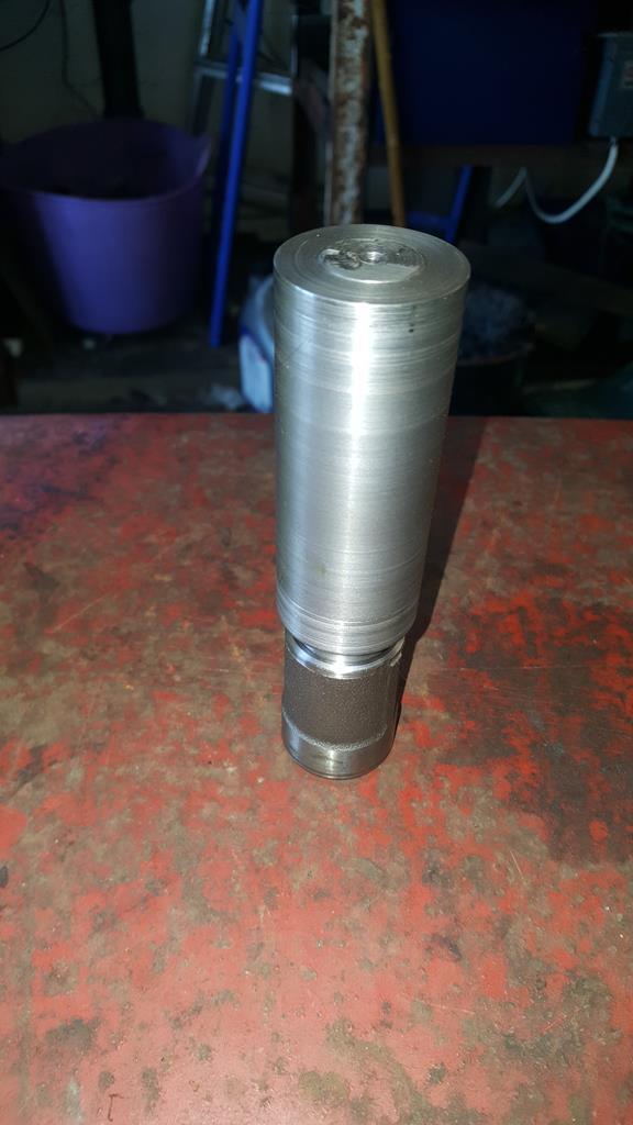 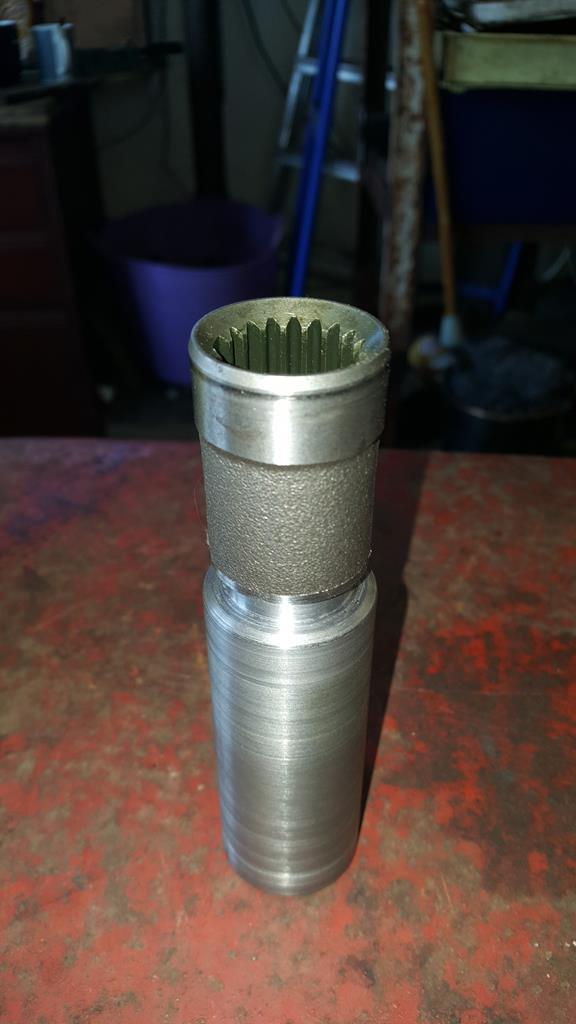 And that is this thread up to date again. I hope you all enjoying my ramblings |
| |
My YouTube Channel www.youtube.com/user/UkWheelHorseBlokeQuote - D'you know, it's people like you, doing totally brilliant and pointless stuff like this that gives me a little hope for humanity |
|
|
|
|
May 20, 2018 16:21:43 GMT
|
I have been mostly spending a lot of time at the lathe turning down this, boring out that, and trueing up the other. Not that many photo's but this was quite interesting to make out of two parts and a bit of welding. It's not quite finished in the photo, only a bit of tidying to do.. 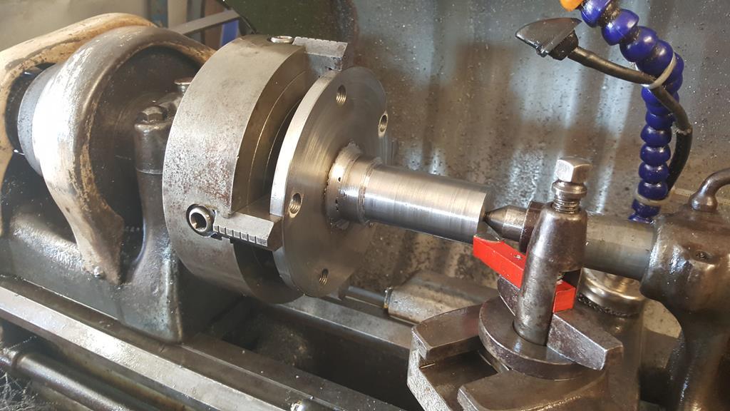 A bored out sprocket is a nice tight fit on the shaft. 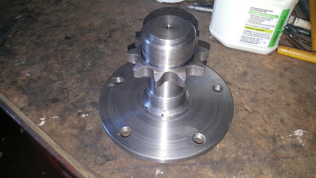 Now the fun part, making the 90'd drive thingy fit in not much space.. It's in there somewhere! 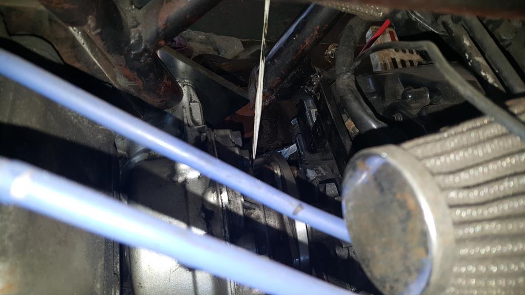 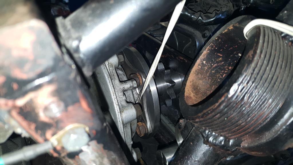 This view might help to see what's going on. Or not! 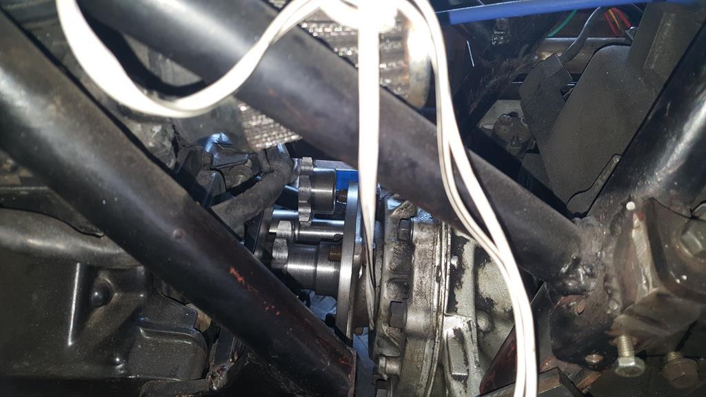 The plan was to fit this sprocket to the shaft that comes from the Honda gearbox.. 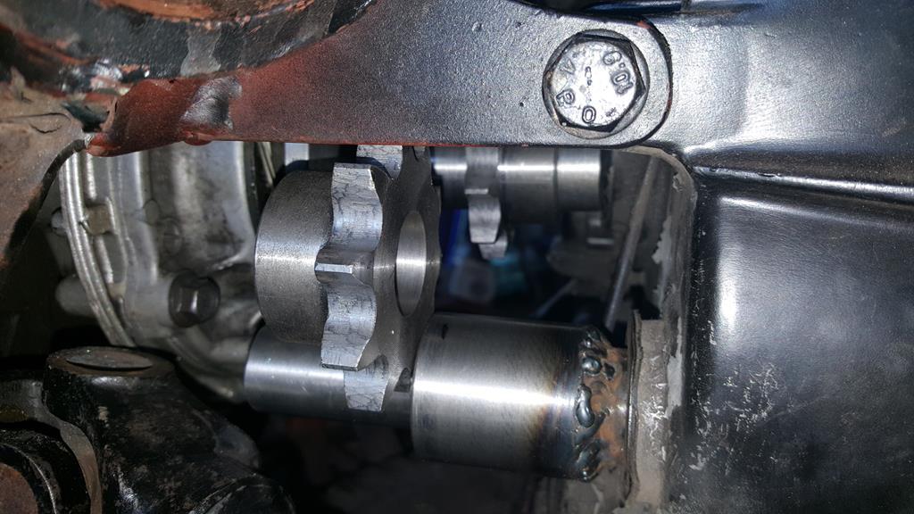 And put this bearing at the end to hold things steady.. The trouble is, not enough space, the drive shaft to the front takes up a fair bit of space too! 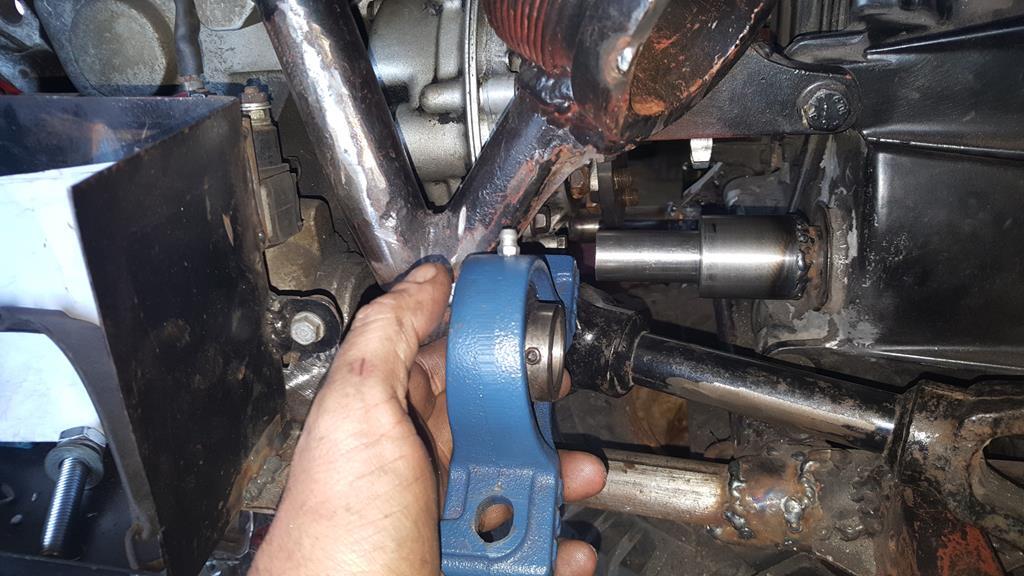 Soooo... The plan now is to mount this bigger bearing a lot closer to the gearbox case and fit the sprocket on the end only much more forward than it was.. Of course I don't have a bearing holder for the bigger bearing! 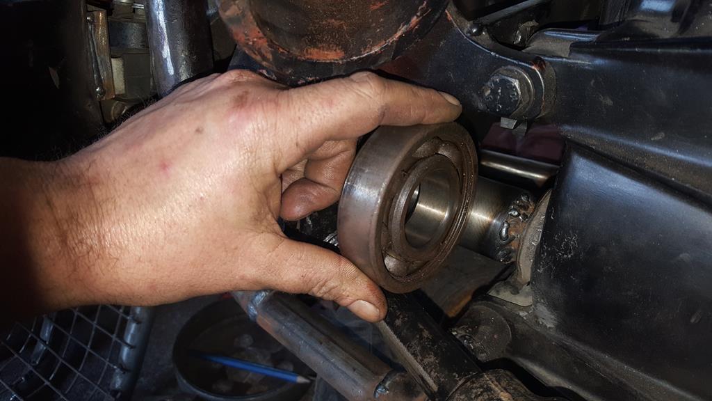 So a bit of thick steel slicing.. 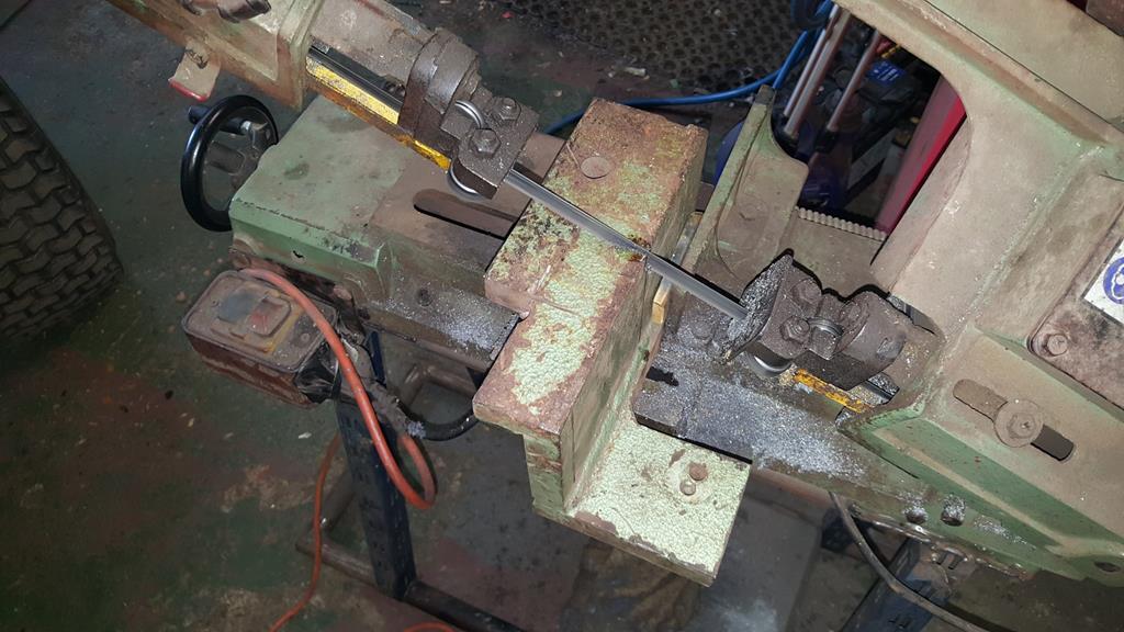 Cut's well for a £10 power saw 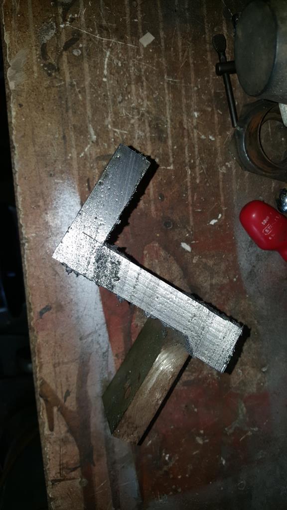 An almost flat plate. 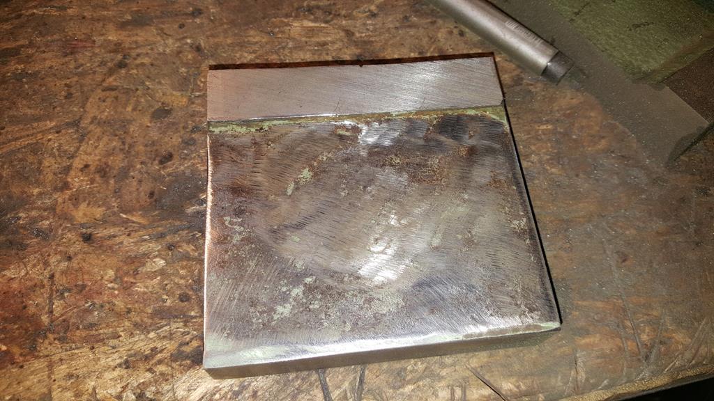 Flat and mostly bored out.. 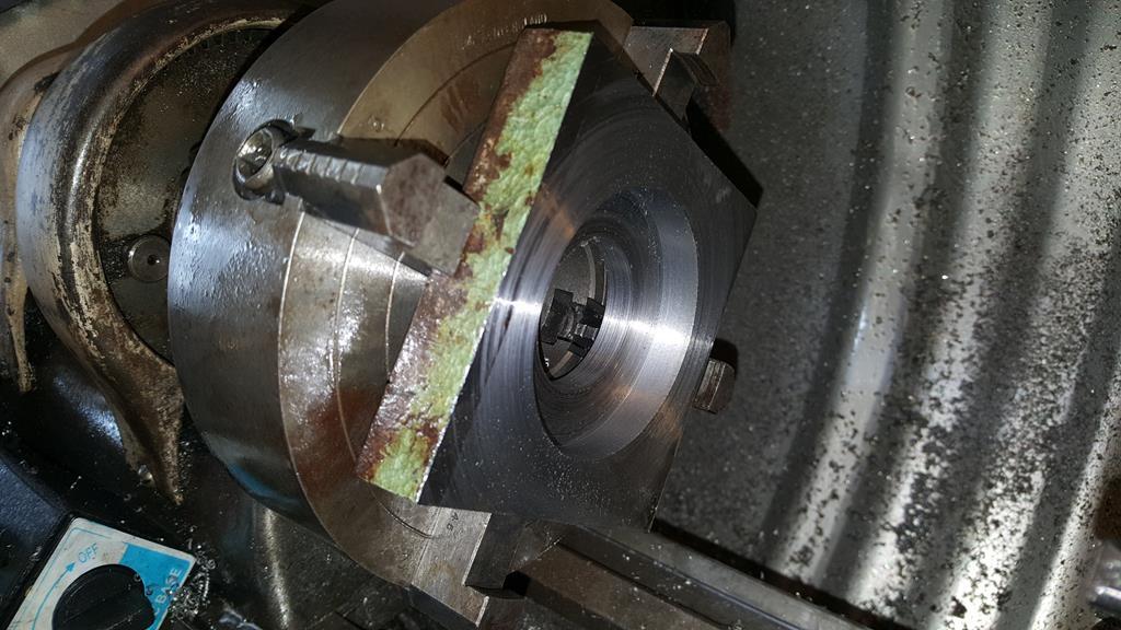 Some more turning later and half of the bearing holder was just the right size, a nice tight fit that will need gentle press pressure to push it in. 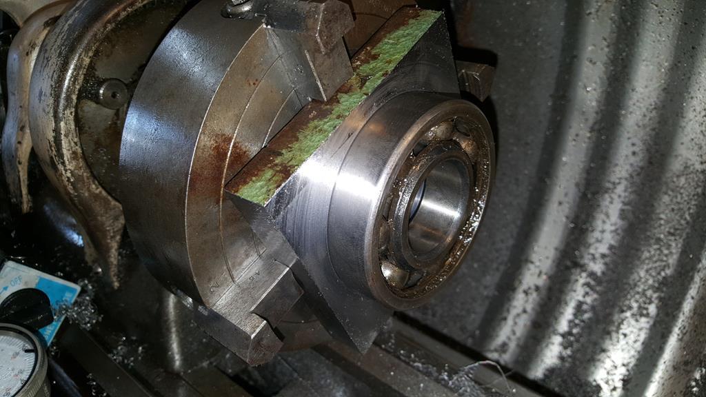 |
| |
My YouTube Channel www.youtube.com/user/UkWheelHorseBlokeQuote - D'you know, it's people like you, doing totally brilliant and pointless stuff like this that gives me a little hope for humanity |
|
|
|
|
May 20, 2018 16:02:18 GMT
|
Right, let's get some more of this update done. The front edges needed a bead of weld to fuse metal together.. To make life easier I clamped on a flat brass bar to weld against as welds will not stick to the brass. 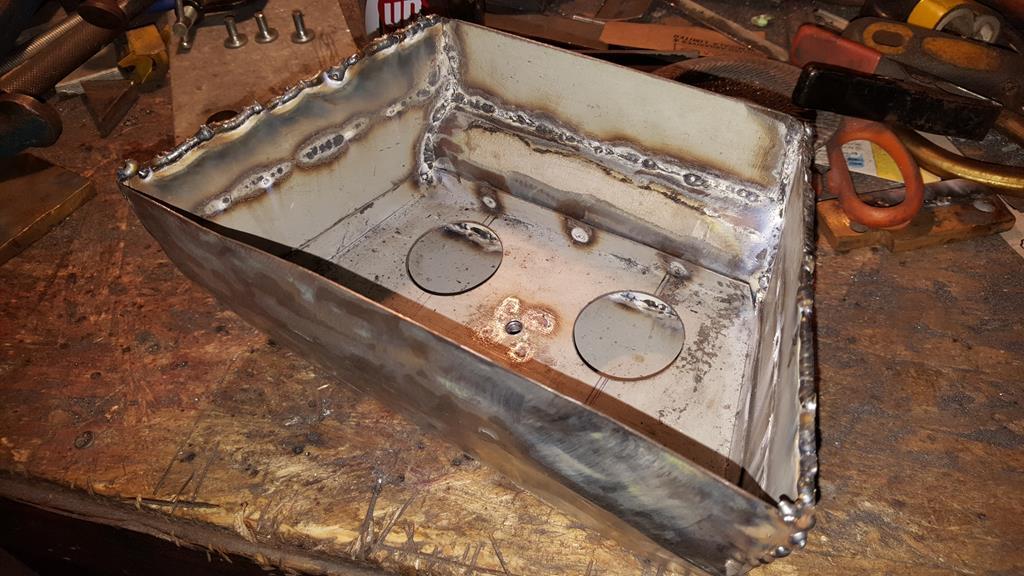 As you will of noticed on the above photo the longest which is also the top panel is a little on the wonky side.. A big thank you to Rob for the square which came in handy for showing how wonky wonky is.. 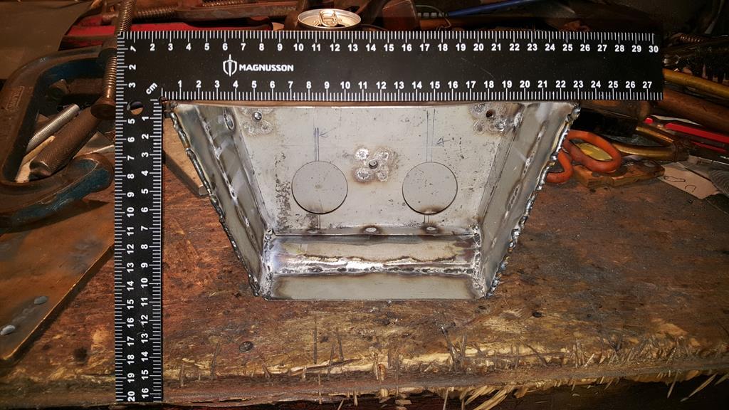 As the metal is too stretched to hammer flat some extra straight strength needs to be added.. Starting with a strip of double skinned steel. 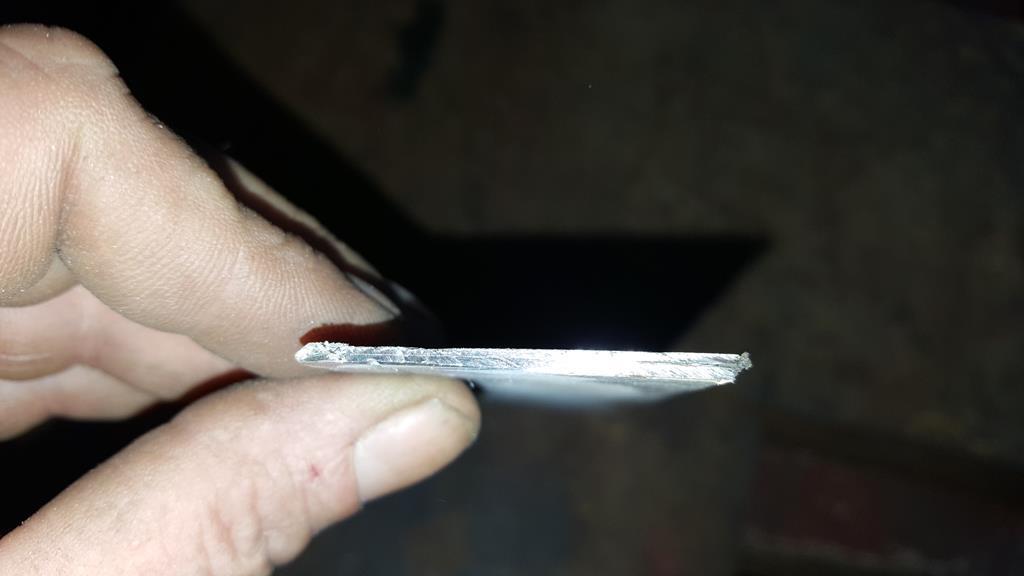 Most of one skin was cut away leaving only a small rolled edge sort of thing. 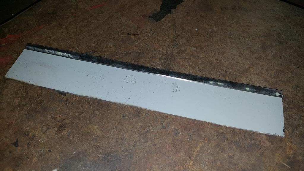 A quick trip to the sheet metal folder which I should use more than I do! 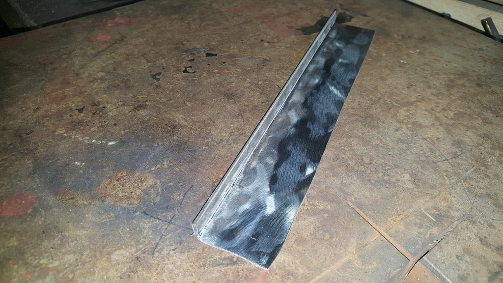 Plug welded inside.. The bit of black box section is only to make sure everything clamps down flat.. 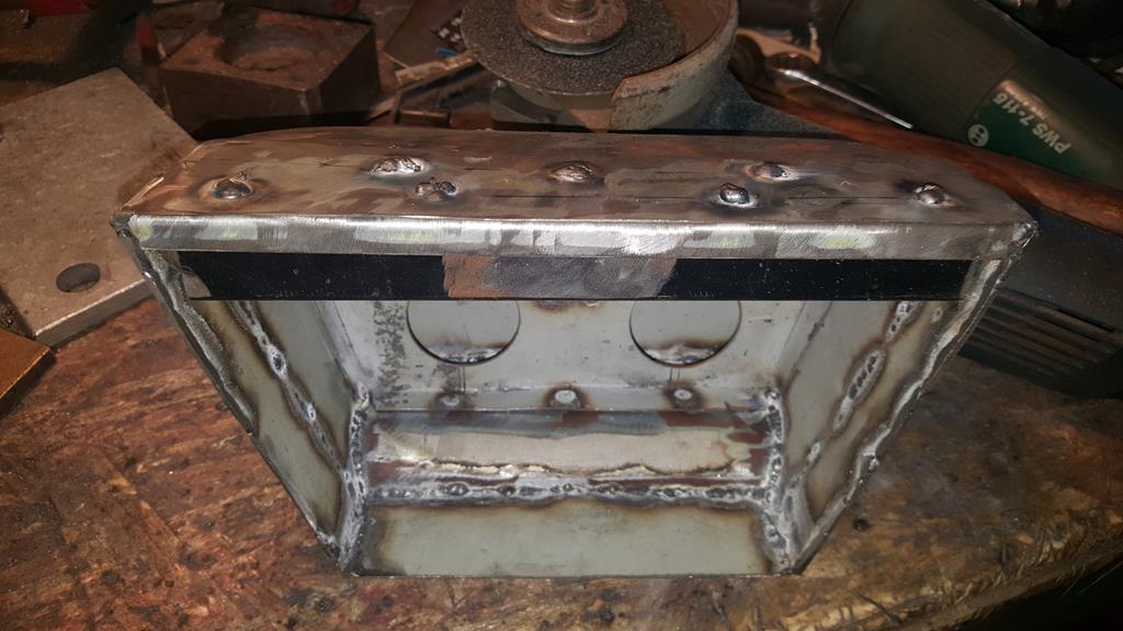 Can you spot a slight problem here? Yep, the box is such a good tight fit it won't come back out again! 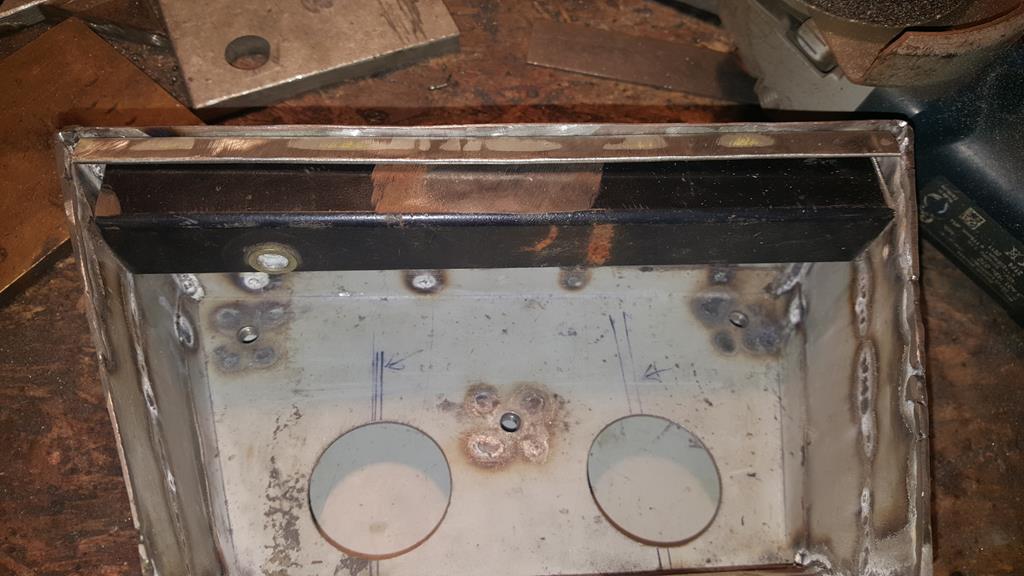 The next step was to make some mounts for the rear light, but a parcel turned up containing these sprockets 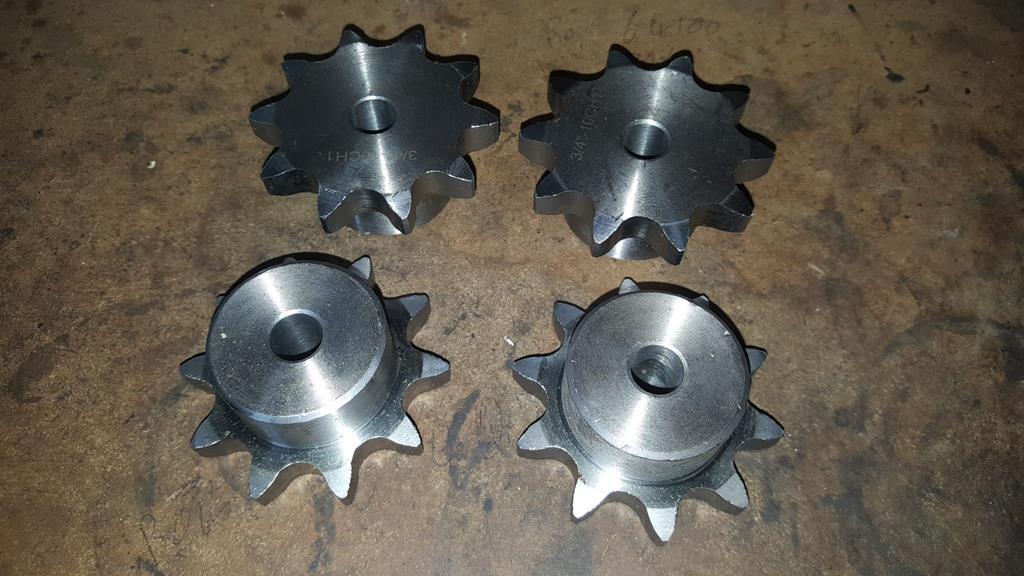 The rear light is going to have to wait, getting the drive train finally finished needs to come first.. Soooooo, the first sprocket on the lathe being bored out to a larger ID.. 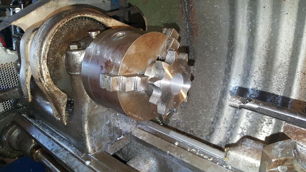 Video time again |
| |
My YouTube Channel www.youtube.com/user/UkWheelHorseBlokeQuote - D'you know, it's people like you, doing totally brilliant and pointless stuff like this that gives me a little hope for humanity |
|
|
|